Mercury Floor Machines Lo-Boy Guide
© 2012 Copy Rights Reserved Mercury Floor Machines, Inc.
© 2012 Copy Rights Reserved Mercury Floor Machines, Inc.
Mercury Floor Machines, Inc.
New Equipment Warranty
Limited Warranty
Mercury Floor Machines, Inc. warrants new equipment against defects in material and
workmanship under normal use and service to the original purchaser. Any statutory implied
warranties, including any warranty of merchantability or tness for a particular purpose, are
expressly limited to the duration of this written warranty. Mercury Floor Machines, Inc. will not be
liable for any other damages, including but not limited to indirect or special consequential damages
arising out of or in connection with the furnishing, performance, use or inability to use the machine.
This remedy shall be the exclusive remedy of the purchaser. The warranty period is subject to the
conditions stated below.
5-Year Warranty on Motor and Chassis, 1-Year Service Labor
Mercury Floor Machines, Inc. warrants electric motors and chassis on all Mercury Floor Machines
to be free from defects in material and workmanship, under normal use and service for ve (5)
years to the original purchaser. Parts replaced or repaired under this warranty are warranted for the
remainder of the original warranty period. Service labor charges are covered for one (1) year from
the date of purchase, when performed by a Mercury-authorized service provider. Freight charges
to and from this service provider will be covered for ninety (90) days from the purchase date.
After this ninety (90) day period, these freight charges will be paid by the equipment owner. Travel
expenses are not covered.
Wear Items on all Machines
Critical Wear Items - bearings, capacitors, clutches, pulleys, rectiers, relays, switches, wheels,
tires and casters are warranted for manufacturing defects for one (1) year from the purchase date.
Normal Wear Items - belts, brushes, bumpers carbon brushes, cords, nishes, squeegees, actuating
cables and gaskets are warranted for manufacturing defects for ninety (90) days from the purchase
date.
All warranties of motors and associated components will be voided: if the machine is used as
a oor sander; if the machines is serviced by anyone other than a Mercury-authorized service
provider; if the machine is mechanically modied; or if the machine is misused or abused.
The warranty starts on the purchase date by the original purchaser from an authorized Mercury
Floor Machines, Inc. distributor, subject to proof of purchase. The machine registration card must
be completed and returned immediately at the time of purchase. If proof of purchase cannot be
identied, the warranty start date is ninety (90) days after the date of sale to an authorized Mercury
Floor Machines, Inc. distributor.
Mercury Floor Machines, Inc.
110 South Van Brunt Street
Englewood, NJ 07631
Phone: (201) 568-4606
Toll Free: (888) 568-4606
Fax: (201) 568-7962
www.mercuryoormachines.com
Important Information and Safety Instructions
Register your Machine at mercuryoormachines.com/registration.aspx
Serial No:
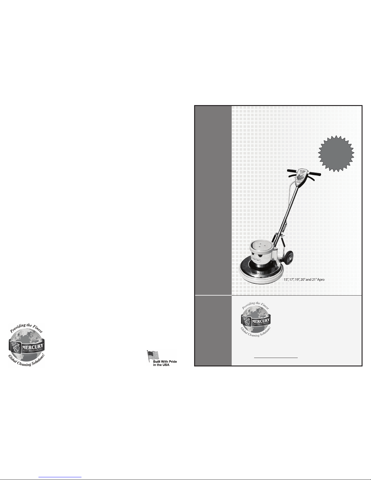
Lo-Boy™ Floor Machine
5 Apron Sizes
Fully Adjustable
Balanced Design
All Metal Chassis
Quiet Motor
Safe & Easy to Use
REGISTER
YOUR
MACHINE
ONLINE!
Safety, Operation and Maintenance
Manual with Parts List
Please read before use!
1.5 HP, 175 RPM
15”, 17”, 19”, 20” and 21”Apron Sizes

1.0 Safe Operating Conditions
READ THIS MANUAL BEFORE USING FLOOR MACHINE. KNOW THE
PROPER OPERATION, CORRECT APPLICATIONS AND THE LIMITATIONS OF
THIS EQUIPMENT BEFORE USE.
Reduce the Risk of Fire, Electric Shock or
Injury:
• This oor machine is designed for indoor use only. Do
not use outdoors. Do not expose to rain.
• Do not wash the motor with owing water. If the motor
gets wet, seek authorized service.
• Keep the vents on this air-cooled motor free from
debris. Do not operate with the motor covered or with
vents blocked. Do not use this machine as a oor
sander.
• Never operate this oor machine near ammable
dusts, liquids or vapors. Never use ammable
solvents as a cleaning agent. Engine sparks and
operating heat can cause re.
• Never handle electrical equipment with wet hands.
Never operate this oor machine with bare feet.
• Unplug the oor machine when not in use and when
servicing the equipment. To unplug, grasp the plug
not the cord.
• Do not operate a oor machine with damaged
handle controls, cord or plug. If the equipment is not
performing properly, seek repair from a qualied
service supplier.
• This oor machine is constructed with electrical
grounding at the plug. Operate only when connected
to a properly grounded outlet. See section 1.2 for
grounding details.
• Prevent electrical cord abuse. Do not close a door
upon the cord, drive equipment over it, or run the oor
machine over it. Do not expose the cord to hot surfaces.
Do not lift, pull or carry this oor machine by the cord.
• Never operate the oor machine over sharp objects that
can be thrown out and harm the operator and damage
the oor. Sweep hard oors before scrubbing or bufng.
Vacuum clean carpets before shampooing or bonnet
cleaning.
• Train your staff in proper use of this oor machine.
(2) Super Heavy-Duty Floor Machine Super Heavy-Duty Floor Machine (11)
7.2 Scrubbing Brush Filaments
Scrubbing brushes are available with a range of bristle types - from the softest for
high-gloss oors, to the most aggressive for heavy soils. Match your brush to the
oor as you match a detergent with the soils.
Nylon is used for general scrubbing. Because nylon softens
when wet, it is great for gentle scrubbing, mopping and
polishing of decorative oors. Nylon will not scratch tile,
terrazzo or coated surfaces. Nylon brushes are durable and long
lasting.
Polypropylene is a common choice for general purpose
scrubbing and works well on both concrete and on coated
oors. Polypropylene brushes typically cost less than nylon, but
do not last as long.
Non-scuff poly is a ner diameter (0.015-0.018”) lament used
for lighter duty scrubbing conditions and on waxed or nished
oors.
Bassine is a soft, natural ber. The end of the bristle splits or
“ags” to build a polishing surface.
Union mix is a mixture of bassine and tampico (another natural
ber). The mixture is stiffer than bassine alone and is used by
more traditional cleaners for scrubbing. It is often replaced by
poly.
Soft abrasive bristle is a 0.018” nylon lament extruded
with a 500 grade grit. It is used for gentle scrubbing and is as
aggressive as a white scrub pad.
Daily abrasive bristle is a 0.035” nylon lament with 180
grade grit. It is used for daily scrubbing of resilient tile and
nished oors and is as aggressive as a red scrub pad.
Stripper abrasive bristle is a 0.022” nylon lament with 120
grade grit. It is used for aggressive scrubbing and light stripping
of resilient oors, terrazzo and concrete. It is as aggressive as a
blue scrub pad.
Heavy-duty stripper abrasive bristle is a 0.050” nylon
lament with 80 grade grit. It is used for very aggressive
scrubbing and stripping of concrete, brick and quarry le. It is
as aggressive as a black scrub / strip pad.
1.1 Electrical Power
This oor machine operates on a 15 amp nominal
115V, 60 Hz, A.C. power circuit. (Motors may be
custom wired at the factory 220V, 50 Hz international
operation.) The, amp, hertz and voltage ratings are
listed on the motor spec label found on each oor
machine. Using voltages above or below those
indicated on the spec label will damage the motor.
Always check your local voltage requirements.
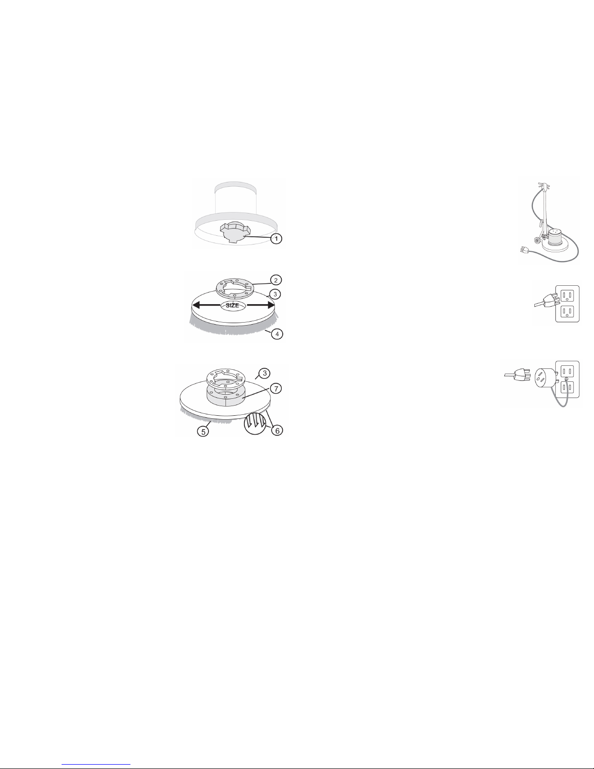
1.2 Grounding Instructions
This oor machine must be grounded while in use
to protect the operator from electrical shock. This
machine is built with a 3-wire cord and a 3-prong
grounding-type plug (Figure 1) to t a properly
grounded receptacle.
Before using this oor machine, make sure a properly
grounded, 3-hole electrical outlet is available. If not
available, as in some older facilities, use an adapter
for connecting a 3-prong plug to a 2-prong receptacle
(Figure 2) to ground the outlet chassis.
IMPORTANT: This adaptor may not be used in
Canada.
IMPORTANT: Never cut off the grounding prong for
use in a 2-prong outlet. By doing so, you have cut off
your protection from electrical shock.
Never assume that all 3-hole outlets are properly
grounded. Check before use.
Never assume that an adaptor connection (as in
Figure 2) is properly grounded. Check the outlet
with a ground fault interrupter device which quickly
indicated if a ground is connected. Correct a faulty
grounding before proceeding.
1.3 Extension Cords are Not Recommended
The oor machine is built with a 50 foot (15 M) safety cord which plugs directly into an
approved outlet. Use of any extension cords is NEVER RECOMMENDED.
(10) Super Heavy-Duty Floor Machine Super Heavy-Duty Floor Machine (3)
7.0 Brush Construction
Your new oor machine provides reliable, efcient,
safe power to your scrubbing brush. To get the best
results, you need to use a brush of the best design and
construction.
Your oor machine is built with a “B” style drive
plug (1). The height and width of the ears on the plug
will match a “B” style or “Universal” clutch plate (2)
mounted on the brush block.
The brush block (3) is constructed of molded plastic
or this plywood. Use a brush with a block diameter 2”
less than your machine apron size.
The bristle material (4) that actually does the
scrubbing is typically 1-1/2” to 2” long. Holes are
drilled in the block and bundles of bristles are folded
in half, forced into the hole and stapled in place
(staple-set).
When the bristles wear down to less than 1/2” long,
they have little exibility and it’s time to replace.
Bristle materials are described on page 11.
7.1 Pad Driver Construction
If you scrub or polish with a non-woven pad, use a
pad driver to connect the pad to the machine.
The brush block (3) is constructed of molded plastic,
t with shorter, stiffer, pad-holding bristles (5) or
“velcro-like” pad-holding hooks (6) and use a riser
(7) to create extra clearance between the block and
the machine apron. With this construction, use a pad
driver with block diameter 1” less than your machine
apron size.
Machine Apron Size 15” 17” 19” 20” 21”
Pad Driver - with 3/4” Riser 14” 16” 18” 20” 20”
Brush - with NO RISER 13” 15” 17” 19” 19”
Figure 1
Figure 2
5.2 Transport
To transport this oor machine from the janitor’s closet
to the work area:
• Lock the handle in the “up” position. Wid the cord
around the handles and the bottom cord hook.
• Tip the machine back onto the transport wheels.
Push or pull the machine by the handle, not by
the cord or any other part of the machine. Travel
carefully.
6.0 Troubleshooting
Never operate this oor machine when the equipment is not performing as expected
or when any part is visibly damaged. The cause and solution for some basic problems
are described below. When repair is needed, take the equipment to an authorized repair
service center.
6.1 Floor Machine will not Run
• Circuit breakers are tripped in the building. Check and reset.
• Equipment is unplugged. Check plug wall and at machine base. Plug in.
• Power cord failure. Test with a working power cord. Lock the handle up and tip the
motor back. Unplug the cord at the motor and plug the motor into your working
power cord.
• IMPORTANT! THIS IS JUST FOR TESTING. When you do this, you have removed
the safety handle controls from the circuit and you are sending power directly to the
motor. If the motor now spins, the problem is in the cord of the handle assembly.
Seek authorized repair service.
• If the motor still does not spin, the problem is either in the male connection at the
motor base or in the motor. Seek authorized repair service.
• Motor sparks or smokes. Seek authorized repair service.
6.2 Electrical Shock to Operator
• Equipment wiring failure or electrical short in the machine. Seek authorized service.
• Poor grounding or no grounding. Test the outlet with a ground fault interrupter.
Retain certied electrician to inspect and repair grounding. NEVER clip off the
ground plug on your cord.
• Repeated circuit breaking. High amp draw and circuit breaking can be an electrical
or mechanical problem. Seek authorized repair service.
6.3 High Vibration
• Pads are not centered on the pad driver. Tip machine back and re-center the pad.
• Uneven wear or warp to pad or brushes. Replace.
• Machine chassis is damaged by dropping. Replace.
(4) Super Heavy-Duty Floor Machine Super Heavy-Duty Floor Machine (9)
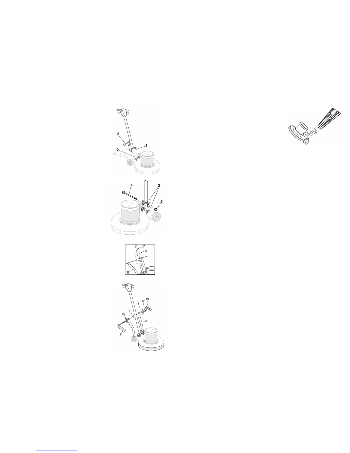
2.0 Install the Handle
This machine handle (1) has been custom t to its
mounting yoke (2) at the factory and then taken apart
for shipping. For easy assembly, make sure that the
handle number on the tag (see right) matched the serial
number stamped on the chassis.
You will need 7/16” wrenches to complete the
assembly:
1. Remove the handle and mounting hardware from
the carton. Bolts, nuts, washers and the locking
lever assembly are in the plastic bag attached to
the handle.
2. Position the handle (1) over the mounting yoke
(2) with the power cord (3) facing away from the
motor. Push the tube down until the bolt holes are
lined up.
3. Insert the long mounting bolt (4) into through the
aligned holes in the yoke and mounting ears (2).
Secure the bolt with a locking nut (5).
4. The handle mounting collar (6) is designed to
slide freely up and down the handle tube (7). This
feature allows the handle to be adjusted for the
comfortable operation of all users.
5. Remove the lever assembly parts from the plastic
bag.
• Align the mounting collar (6) and the two bent
handle braces (7).
• Place the thick spacer with a rectangular neck
of the lever.
• Insert the shaft through the mounting hole in
the right handle brace, the mounting collar and
the left handle brace.
• Place a spacer (11) on the shaft.
• Place the locking wing nut (13) on the shaft.
• Adjust the wing nut for tightness. When
correctly installed, the collar slides easily when
the cam-engineered locking lever is “up,” but is
rmly xed when the lever is “down.”
(8) Super Heavy-Duty Floor Machine Super Heavy-Duty Floor Machine (5)
5.0 Operating Tips
• For indoor use only. Sweep abrasive soils before
scrubbing.
• While the brush or pad driver is spinning, keep the oor
machine moving to avoid “donut” burns on the oor.
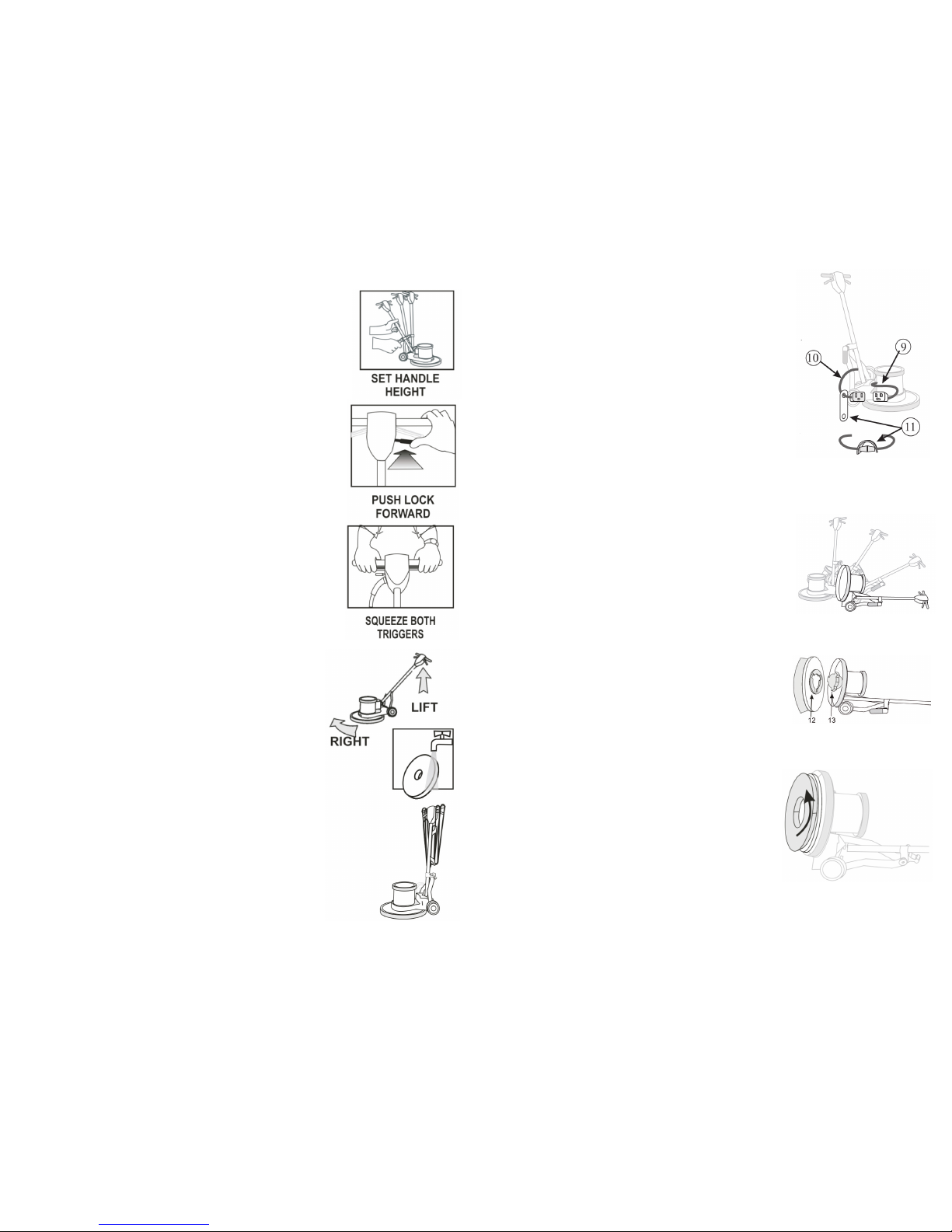
To Start Operation:
• Unlock the handle by raising the locking lever.
• Lower the handle to a comfortable position, typically
waist height.
• Relock the handle by pushing the lever down. NEVER
OPERATE THE MACHINE WITH THE HANDLE
UNLOCKED.
• This oor machine is a high torque motor. Hold the
machine rmly with both hands when starting up.
• Push the red safety interlock switch forward to unlock the
dual triggers.
• Squeeze the dual triggers to release power to the motor.
Once power is on, either trigger will keep power to the
motor.
• To stop the oor machine release both triggers.
• The spinning brush helps move the oor machine. (Lift
the handle slightly to work to the right. Push the handle
down slightly to work to the left.)
5.1 To Store your Machine
• Lock the handle in the “up” position. Tilt the machine
back and remove the pad driver or brush.
• Wind the cord around the handles and the bottom cord
hook.
• Wash brushes or pads and hang to dry. Never store
machine standing on the brush.
• Inspect and maintain equipment on a regular schedule for
best results.
• Check and clean pads after each operation. Remove soil
and chemical buildup. Replace worn or damaged pads.
• Check the triggers and switches for proper operation.
• Repair or replace damaged skirts and dumpers.
• Use air pressure or vacuum to remove dust and debris
from the motor vents.
• Report problems and repair promptly.
2.1 Attach the Power Cord
The triple-wire grounded power cord has been factory-
installed into the handle tube. A exible rubber cable
connector (11) is used to secure the plug-in connections.
The oor machine ships with this connector mounted
on the cord coming out of the handle (10). Stretch the
connector and slip the male connector (9) (coming out of
the motor housing) through the connector hole and then
into the female connector.
Now, plug the end of the 50-foot cord into a grounded
power outlet. Squeeze the triggers on the handle and check
for power to the motor.
2.2 Install a Brush or Pad Driver
A brush or pad driver mounts onto your oor machine with
a “B” style Universal clutch plate.
Unplug the oor machine. Lock the machine handle in
the “up” position and tip the oor machine back onto the
handle.
Slide the brush or pad driver clutch plate (12) over the
drive plug (13).
Give the brush a quick counter-clockwise spin to lock the
brush onto the drive plug.
Now, lower the machine back onto the brush.
You’re ready to go to work.

Item Description Part No. Qty. Needed
1 Switch Box Back A-104 1
2 Handle Tube Screw B-23 2
3 Switch Box Closing Screw B-21 4
4 Strain Relief Clip M-213 1
5 Ground Wire Screw B-68 2
6 Rubber Spacer - Yellow M-218-Y 2
7 Hand Grip M-218 2
8 Handle Tube Insert M-247 1
9 Handle Tube Assembly M-206 1
10 Cable Hook Screw B-2 2
11 Cable Hook A-164 1
12 Sliding Collar A-111 1
13 Oval Hole Cam Washer B-37 1
14 Cam Lock Wing Nut B-25 1
15 Cam Split Washer B-39 1
16 Bent Brace M-216 2
17 Yoke Bolt B-18A 2
18 Yoke Nut B-19 2
19 Handle Tube Cable G-16 1
20 Black Rubber Cable Connector M-249 1
21 Cable Grommet B-63 1
22 Rectangular Hole Cam Washer B-67 1
23 Cam Assembly C-100 1
23A Complete Cam Assembly Kit (Includes 1 each of CCA 1
Drawing Items #13, 14, 15, 22, 23)
24 50-Foot Cable, 14/3-Gauge - Yellow G-14-50 1
25 Switch Mounting Plate G-30-B 1
26 Switch Plate Screw B-1 2
27 Int. Tooth Lock Washer (for Switch) B-35 1
28 Insulated Flag Wire Connector G-48 2
29 On-Off Switch And Plate Assembly G-30-AB 1
30 Lock Washer B-33 1
31 Trigger Return Spring G-30-CT057 1
32 Label For Switch Box 1
33 Switch Box Front A-103 1
34 Wire Connector G-47 1
35 Trigger A-105 2
36 16” Crossbar M-211-A 1
37 Safety Interlock Assembly SIA-1 1
38 Trigger Pin B-70 2
39 Crossbar Screw B-22 2
40 Yoke Bolt B-14 1
41 Yoke A-1001 1
42 Acorn Nut For Yoke Bolt B-10 1
43 Drip Cap Mounting Screw B-151 3
44 66-Frame Drip Cap Cover M-241 1
45 66-Frame Drip Cap Cover Bumper M-239 1
46 Cork Drip Cap Gasket M-248 1
47 Split Washer B-32 4
48 Motor 66 Frame 1.5 HP With Gearbox, 115V MOTOR /GB-LH/E 1
49 Gear Box, 11:1, Triple Planetary GB96008 1
50 Wheel Axel Bolt B-15, BDP 2
51 Spring Washer B-51 12
52 6” Wheel M-245 2
53 Wheel Carriage A-117 2
54 Spring B-30 2
55 9” Axel M-217 1
56A Base Casting 15” A-124 1
56B Base Casting 17” A-134 1
56C Base Casting 19” A-127 1
56D Base Casting 20” A-129 1
56E Base Casting 21” A-129 1
57 Axel Pin B-45 2
58 Wheel Axel Pin B-46 2
59 Bumper Screw B-68 2
60 Bumper Strap 15” (order 43” of Bumper Strap) Bumper Strap 2
61A Bumper 15” - Yellow M-232-15/Y 1
61B Bumper 17” - Yellow M-232-17/Y 1
61C Bumper 19” - Yellow M-232-19/Y 1
61D Bumper 20” - Yellow M-232-21/Y 1
61E Bumper 21” - Yellow M-232-21/Y 1
62 1/4” Medium Split Washer B-32 3
63 Cap Screw B-31 3
64 Scrubber Plug B-50 1
65 Label for Motor 1
(6) Super Heavy-Duty Floor Machine Super Heavy-Duty Floor Machine (7)
3.0 Machine Schematic Drawing 4.0 Machine Parts List
This manual suits for next models
1
Table of contents
Other Mercury Floor Machines Floor Machine manuals


Popular Floor Machine manuals by other brands

Windsor
Windsor LB1500 operating instructions

Sanitaire
Sanitaire SC6010A Repair parts list

Pioneer Eclipse
Pioneer Eclipse PE430GP Operator's manual

Clarke
Clarke FOCUS 00310S Operator's manual

Numatic
Numatic TTB 345S operating instructions

Nilfisk-Advance
Nilfisk-Advance SR 9772 56109414 Instructions for use


Nilfisk-Advance
Nilfisk-Advance BR 1100C Instructions for use

Hawk
Hawk AR517 owner's manual

Kärcher
Kärcher KM 150/500 R Bp manual

U.S. Products
U.S. Products KING COBRA 310 Information & operating instructions

Westermann
Westermann Cleanmeleon 2 PRO Operating instruction

Edco
Edco 2D-HD Operator's instruction manual