Mercury Champ 600 User manual

VERSION 040711

2 Fender Champion “600”•Mercury Upgrade Kit
ThisprojectanditsdocumentationistheresultoftechnicalinvestigationsmadebytheengineeringstaffofMercury Magnetics.Thedisclosureoftheinformationhereinmaypertaintoproprietaryrightsand
thefurnishingofthesedocumentsdoesnotconstituteanexpresedorimpliedlicensetousesuchmaterials.
Ifyoudonotknowhowtoreadaschematic,westronglyrecommend
thatyoutakethisprojecttoaqualiedtechnicianforinstallation.
AllMercury Magneticsproductsare100%handmadebyusinCalifornia,USA.
Copyright©2007–2011byMercury Magnetics.AllRightsReserved.Mercury Magnetics,Mini-Choke,
MercuryUpgradeKit,and“TheHeart&SoulofYourAmp”sloganaretrademarkslicencedtoMercury Magnetics.Axiom
andToneCloneareregisteredtrademarkslicensedtoMercury Magnetics.FenderandChampion“600”aretrademarksof
FMIC(FenderMusicalInstrumentsCorp.).Mercury MagneticsisnotafliatedwithFMICAmplication.Thisprojectandits
documentationistheresultoftechnicalinvestigationsmadebytheengineeringstaffofMercury Magnetics.Thedisclosureofthe
informationhereinmaypertaintoproprietaryrightsandthefurnishingofthesedocumentsdoesnotconstituteanexpresedorimplied
licensetousesuchmaterials.
Mercury MagneticsproductsareUL(UnderwritersLaboratoriesInc.)recognizedcomponentsfortheUSAandCanada.OBJY2
componentsystems,electricalinsulation,E120568.ULRecognition,class130(b)–Class200(n).OBJY8componentsystems,
electricalinsulation,certiedforCanada,class130(b)–Class200(n).
Mercury MagneticstransformersandotherproductsareincompliancewiththeEuropeanUnionRoHSDirective2020/95/ECwith
respecttothefollowingsubstances:lead(Pb),mercury(Hg),cadmium(Cd,hexavalentchromium(CR(VI)),polybrominatedbiphenyls
(PBB),andpolybrominateddiphenylethers(PBDE).
Attention: Modifying your Fender Champion “600” amp voids the FMIC warranty!
Written & produced by the staff of
Circuitry design by Alan Cyr
(www.Amp-Exchange.com)
9167IndependenceAve.
Chatsworth,CA91311
(818)998-7791•FAX:(818)998-7835
Skype:paul.patroneteorpatrick.selfridge
www.MercuryMagnetics.com
info@MercuryMagnetics.com

Fender ’Champion “600”•Mercury Upgrade Kit 3
ThisprojectanditsdocumentationistheresultoftechnicalinvestigationsmadebytheengineeringstaffofMercury Magnetics.Thedisclosureoftheinformationhereinmaypertaintoproprietaryrightsand
thefurnishingofthesedocumentsdoesnotconstituteanexpresedorimpliedlicensetousesuchmaterials.
SOLDERING NOTE:YourampisassembledusingRoHScompliant,lead-freesolder.Workingwithlead-freesolderisdifferentthan
standardsolder.Generallyahotterironisnecessary.Formoreinformationwerecommenddoingaweb-earchfor“lead-
freesolderingtechniques.”
CAPACITOR DISCHARGE WARNING:Safedischargingofltercapacitorsmatters.Itisessentialforyoursafetyand
topreventdamagetotheamp’scircuitry,thatlargeorhighvoltagecapacitorsbefullydischargedbeforemeasurements
aremade,solderingisattempted,orthecircuitryistouchedinanyway.Forinformationonhowtodothis,web-search
“capacitordischarging.”Alsoseetheappendixforadditionalinformation.
CAPACITOR POLARITY:Notethatmanycapacitorshavepositiveandnegativepolarity,andarestampedaccordingly.
BesurethattheirpolarityiscorrectwhensolderingtoaPCB.
BRAIDING, TWISTING AND COILING LEADS:Donotbraid,twistorcoilthepowertransformer’sB+leadwire.Check
ourreferenceillustrationsandphotostoseewhichleadsaretwistedtogether.Typicallyonlythelamentleadsofthe
powertransformer.Otherpositioningofleadsmaybenecessarytominimizeampnoise.Followarediagramsand
instructsforoptimalperformance.
TRIMMING TRANSFORMER LEADS:Tominimizenoise,measureandtrimthesolderableleadlengthsofthetrans-
formersandMini-Choke™.Routeallwirescleaningaroundthetubes,chassis,etc.
CLIPPING vs. UNSOLDERING PCB COMPONENTS:TomakethisUpgradeitwillbenecessarytoremoveseveral
componentsfromtheMainPCBoftheamp.Duetoqualityissueswithmodernoff-shorePCBmanufacturing,itcan
bedifculttounsolderanitemwithoutcreatingotherproblems,themosttypicalofwhichisaneyeletdetachingfrom
thePCB.Thereforewe’veindicatedwhichcomponentsshouldbeclippedvs.unsoldered.Tounsolderheatyouriron
to800ºF,thenveryquicklyheatinguponesideoftheexistingsolderconnectionwhilepullingitthroughontheother.If
theironisnothotenough,oryoulingertoolong,theeyeletwillgetdamaged(orfalloff).Ifthishappensyou’llhaveto
fabricatearepair,orcreatedajumpertoatrace.Seethismanual’sappendicesfortips.
POWERING UP A GUITAR AMP:Aftermakinganymodicationstoanamp’scircuit(e.g.thisUpgrade)useaVariac
alongwithancurrentmeter(somehaveboth)toslowlyapplypowertotheampwhilecheckingforwarningsignsof
circuitryerrorsorshorts.Seethesectionon“UsingaVariac”attheendofthismanual.
LOADING OUTPUT TRANSFORMERS:Youmustconnectaspeakerorspeakercabtoyourampbeforepoweringit
up.Withoutaloadtheoutputtransformerwillblow.
MINI-CHOKE FACTOID:AMercuryMini-Choke™replacesaresistorandaddsadisernableamountoftonaldimen-
siontothecircuit.
TRANSFORMER BREAK IN PERIOD:Asageneralrule,transformersrequireapproximately30hoursofplaying time
tobefullybrokenin.PleaserefertoMercury’swebsiteformoreinformation.
BE SAFE! ALWAYS USE PROTECTIVE EYEWEAR!
Table of Contents
Referencephotosofstockamp......................................................................4
Partslist.........................................................................................5
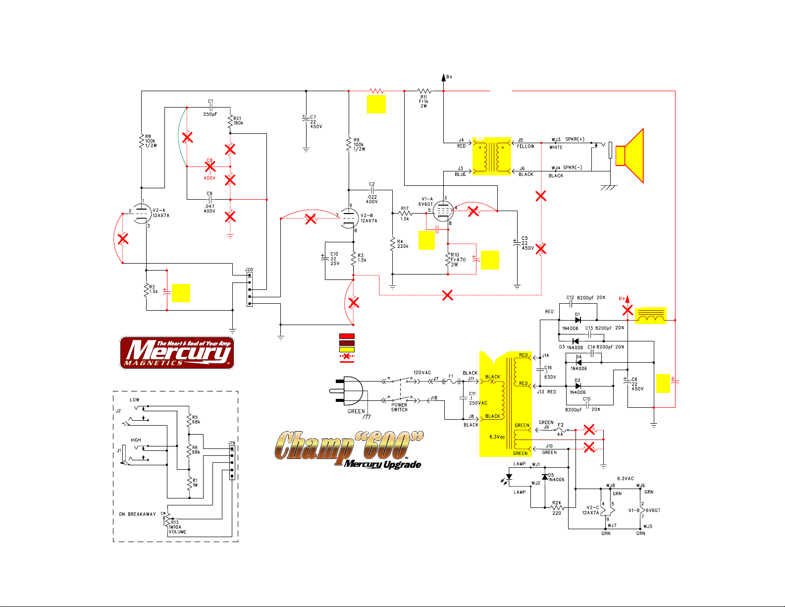
MercuryUpgradewiringschematic...................................................................6
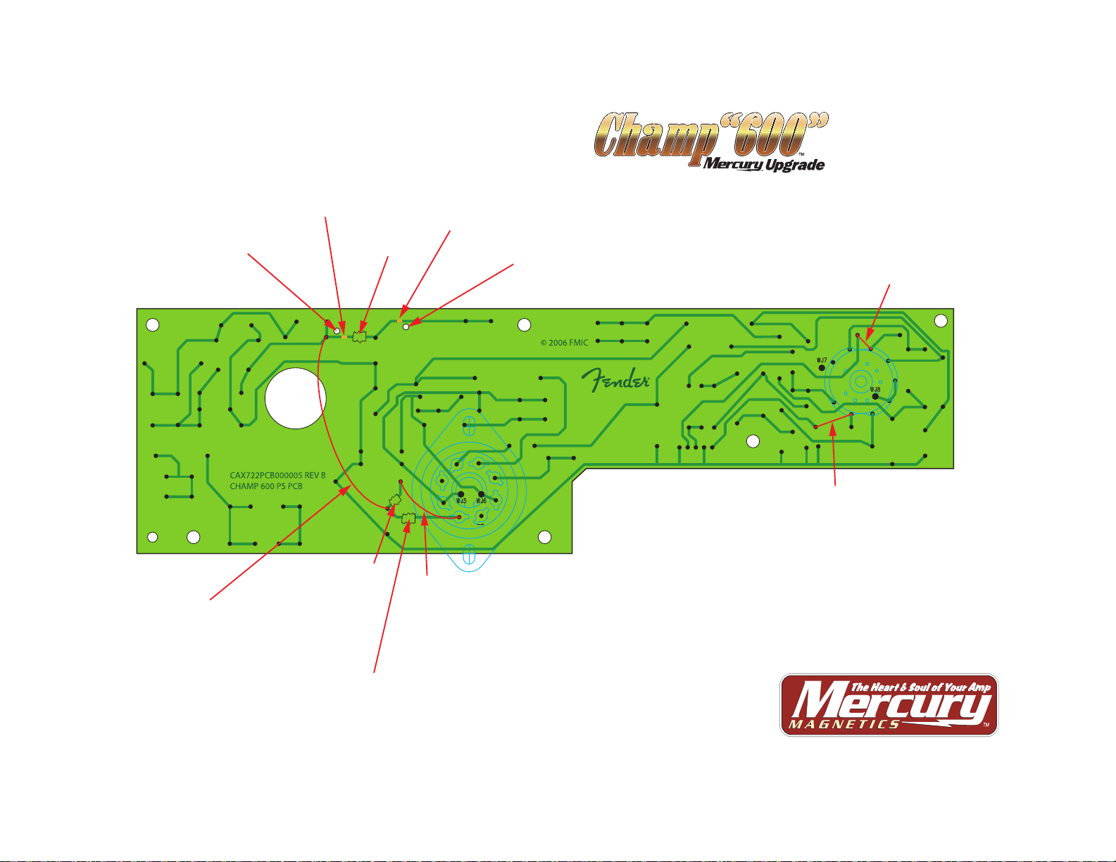
MercuryUpgradePCBlocationdiagram...............................................................7
Transformersandchokespecicationssheets.........................................................10
Transformerlocationsonthechassis.................................................................13
How-Toillustrations...............................................................................14
Appendices:
UsingaVariac................................................................................23
Tips’nTricks–WorkingonPCBs.................................................................26
TheOutputTransformerCircuit...................................................................28
DANGER!DischargingthoseFilterCaps!...........................................................29
CAUTION!Thevoltagesinyourampliercanbedangerous.Transformersandchokesarenotuserservicableparts.Installationof
thesecomponentsshouldalwaysbeperformedbyanexperiencedtechnician.Thesimpleabilitytouseasolderingironisnotenough
toqualifya“do-it-yourselfperson.”Thosewhoareinexperiencedinworkingwithelectroniccircuitsshouldneverattempttoservicetheir
ampliers.Householdlinecurrentscanbedeadly!!Transformers,chokesandlargeltercapacitorscanstoredangerouschargesfor
severaldays,orlonger,aftertheamplierhasbeenunplugged.Nevertouchtheterminalsofthesecomponentswithoutbeingcertain
oftheirchargestatus.Riskofshockanddamagetoequipmentmayresultfrommishandlingand/orimproperuseofthesecomponents.
Pleaseusecommonsenseandalwaysthinksafetyrst.Afterall,greattoneismostenjoyedwhenyouarealivetohearit.
Recommended tools for this project:
• Goodqualitysolderiron(capableoftempsat>800ºF)
• Electronicsgradesolder
• Soldersuckerand/orwick
• Dremel Toolwith1/16"bit,reamerandsmallgrinder*
• Setofscrewdrivers(Philips)
• ExactoknifeforcuttingandscrapingPCBtraces*
• Smallneedle-noseplyers
• Wirestrippers
• Loctite 290(green)
• PureisopropylalcoholandQ-tips
• Variacandcurrentmeter
*Dremel ToolcanbeusedtocuttracesanddrillholesinPCB.

4 Fender Champion “600”•Mercury Upgrade Kit
ThisprojectanditsdocumentationistheresultoftechnicalinvestigationsmadebytheengineeringstaffofMercury Magnetics.Thedisclosureoftheinformationhereinmaypertaintoproprietaryrightsand
thefurnishingofthesedocumentsdoesnotconstituteanexpresedorimpliedlicensetousesuchmaterials.
ThestockChamp“600”chassisreferencephotographs.
POWER
TRANSFORMER POWER
TRANSFORMER
SPEAKER
OUTPUT
6V6
POWER TUBE 12AX7
PREAMP TUBE

Fender ’Champion “600”•Mercury Upgrade Kit 5
ThisprojectanditsdocumentationistheresultoftechnicalinvestigationsmadebytheengineeringstaffofMercury Magnetics.Thedisclosureoftheinformationhereinmaypertaintoproprietaryrightsand
thefurnishingofthesedocumentsdoesnotconstituteanexpresedorimpliedlicensetousesuchmaterials.
Your Mercury Upgrade Kit for the Champion “600” includes these components:
Mercury AxiomPowerTransformerwithmountinghardware
Mercury AxiomOutputTransformer
Mercury AxiomMini-Choke
Mercury Magnetics“Equippedwith”metalplate
CD-ROMwithphotographicstep-by-stepinstructions.
Mercury-suppliedreplacement6”speaker.
Two10mF50–63Vcapacitors(axial,electrolytic)
One270rF500Vcapacitor(disk,silvermica).
One4.7KW2Wresistor(axial,ameproof).
Twosetsof8-32x1/4”(withoptional1/2”)bolts,nuts,washersandlockingwashers(formountingtheMini-
Chokeonthechassis).
Foursetsof8-32x1/2”bolts,nuts,washersandlockingwashers(formountingOTtochassis).
Foursetsof8-32nutsandlockingwashers(formountingPTtochassis).
Onecoilof18gaugebusswireasjumpers.
Onecoilof18gaugeshieldedwireasjumpers.
Twocoilsof20gaugeshieldedwireforlamentsupplyleads.
COMPONENT IDENTITY CHART
MercuryAxiom
Mini-ChokeC600-C MercuryAxiom
power transformer C600-P
MercuryAxiom
output transformer C600-O
Mercury
nameplate
Fully-illustrated
CD-ROM
4.7KW1-wattresistor
(ameproof)
Replacement
speaker
Coilof
busswire
Coilof
shielded
busswire
2Xcoilsof
shielded
lamentwire
10mF50-63voltcapacitor
(electrolytic,axial)
270rF500voltcapacitor
(silvermica,disk)
1/2”&1/4”8-32set
forMini-Choke
1/2”8-32setforOT
1/2”8-32setforPT

6 Fender Champion “600”•Mercury Upgrade Kit
ThisprojectanditsdocumentationistheresultoftechnicalinvestigationsmadebytheengineeringstaffofMercury Magnetics.Thedisclosureoftheinformationhereinmaypertaintoproprietaryrightsand
thefurnishingofthesedocumentsdoesnotconstituteanexpresedorimpliedlicensetousesuchmaterials.
ADD JUMPER
JUMPER
REMOVE
RESISTOR
R7
REMOVE
REMOVE
RESISTOR
R19
REMOVE
RESISTOR
R25
REMOVE
RESISTOR R15
REMOVE
RESISTOR
R16
REMOVE
RESISTOR
R22
REMOVE
RESISTOR
R20
R12
4.7kΩ
2W
C3
10µF
50–63V
CENTER TAP
GREEN/YELLOW
VERSION: 10-14-10
www.MercuryMagnetics.com
www.Amp-Exchange.com
This project and its documentation are the result of technical investigations made by the engineering staff of Mercury Magnetics. The disclosure of the information herein may pertain to proprietary rights, and the furnishing of these documents does not constitute an expressed or implied
license to use such materials. Copyright © 2007–2010 by Mercury Magnetics. All Rights Reserved. Fender is a registered trademark of FMIC. Champion and Chamption “600” are trademarks of FMIC. Axiom and ToneClone are registered trademarks licensed to Mercury Magnetics.
Mercury Magnetics, Mini-Choke and “The Heart & Soul of Your Amp, are trademarks licensed to Mercury Magnetics. Mercury Magnetics is not affiliated with FMIC (Fender Musical Instruments Corp.).
C4
22µF
450V
X2
10µF
50–63V
X1
270ρF
500V
Mercury
supplied
replacement
15W–4Ω speaker
ADD JUMPER
REMOVE
RESISTOR
R23
OPTION: ADD JUMPER
HERE FOR MORE GAIN
REMOVE
RESISTOR
R18
ADD JUMPER
REMOVE RESISTOR
R14
ADD JUMPER
REMOVE
RESISTOR
R26
Notes: (unless otherwise indicated)
1. All resistors in ohms, 5%; 1/4W.
2. All unpolarized capacitors in mF, 10% or better;
50V minimum (power supply bypass capacitors
are 20%).
3. All polarized capacitors in µF, 20%; 50V minimum.
4. All DC voltages are measured with no signal.
5. All AC voltages are +/- 10%.
= Modification
= Mercury Magnetics transformers
= New or moved part
= Removed part or connection
= Buss wires as jumpers or new connections
Mercury choke
C600-C
Mercury output
transformer
C600-O
Mercury power
transformer
C600-P

Fender ’Champion “600” • Mercury Upgrade Kit 7
This project and its documentation is the result of technical investigations made by the engineering staff of Mercury Magnetics. The disclosure of the information herein may pertain to proprietary rights and
the furnishing of these documents does not constitute an expresed or implied license to use such materials.
VERSION: 04-22-08
Revision: 04-06-11
= New or moved part
LEGEND:
= Removed part or connection
= Buss wires as jumpers or new connections to the TOP of the PCB
= Buss wires as jumpers or new connections to the BACK of the PCB
10µF
50–63V
4.7kΩ 2W
X1 X2
10µF 50-63V
270ρF 500V
Top of Main PCB Modifications
JUMPER
JUMPER
JUMPER
JUMPER
JUMPER
JUMPER
JUMPER
Option: Jumpering R18
gives you higher gain.
JUMPER
www.MercuryMagnetics.com
On the next 3 pages are 3 schematics. They show the process of making the Mercury Upgrades to the main circuit board of a Fender Champion “600” (version 1).
This page shows the front of the board with the Upgrades applied without external connections.
This project and its documentation are the result of technical investigations made by the engineering staff of Mercury Magnetics. The disclosure of the information herein may pertain to proprietary rights, and the furnishing of these documents does not constitute an expressed or implied
license to use such materials. Copyright © 2007–2011 by Mercury Magnetics. All Rights Reserved. Fender is a registered trademark of FMIC. Champion and Chamption “600” are trademarks of FMIC. Axiom and ToneClone are registered trademarks licensed to Mercury Magnetics.
Mercury Magnetics, Mini-Choke and “The Heart & Soul of Your Amp, are trademarks licensed to Mercury Magnetics. Mercury Magnetics is not affiliated with FMIC (Fender Musical Instruments Corp.).

8 Fender Champion “600” • Mercury Upgrade Kit
This project and its documentation is the result of technical investigations made by the engineering staff of Mercury Magnetics. The disclosure of the information herein may pertain to proprietary rights and
the furnishing of these documents does not constitute an expresed or implied license to use such materials.
VERSION: 04-22-08
Revision: 04-06-11
= New or moved part
LEGEND:
= Removed part or connection
= Buss wires as jumpers or new connections to the TOP of the PCB
Top of Main PCB Modifications
www.MercuryMagnetics.com
This project and its documentation are the result of technical investigations made by the engineering staff of Mercury Magnetics. The disclosure of the information herein may pertain to proprietary rights, and the furnishing of these documents does not constitute an expressed or implied
license to use such materials. Copyright © 2007–2011 by Mercury Magnetics. All Rights Reserved. Fender is a registered trademark of FMIC. Champion and Chamption “600” are trademarks of FMIC. Axiom and ToneClone are registered trademarks licensed to Mercury Magnetics.
Mercury Magnetics, Mini-Choke and “The Heart & Soul of Your Amp, are trademarks licensed to Mercury Magnetics. Mercury Magnetics is not affiliated with FMIC (Fender Musical Instruments Corp.).
This page is similar to the previous schematic, but shows the external connections to the Main PCB.
X1
C4
X2
SPEAKER JACK
FILAMENT SUPPLY LEADS
(TWISTED PAIR)
TO OUTPUT
TRANSFORMER TO CHOKE
DRILL 1/16” HOLES
FOR CHOKE LEADS
TO POWER
TRANSFORMER
(GREEN AND BLACK SETS ARE TWISTED PAIRS)
TO ON/OFF
SWITCH
TO PILOT
LIGHT
(TWISTED PAIR)
TO OUTPUT
TRANSFORMER
C
E
N
T
E
R
T
A
P

Fender ’Champion “600”•Mercury Upgrade Kit 9
ThisprojectanditsdocumentationistheresultoftechnicalinvestigationsmadebytheengineeringstaffofMercury Magnetics.Thedisclosureoftheinformationhereinmaypertaintoproprietaryrightsand
thefurnishingofthesedocumentsdoesnotconstituteanexpresedorimpliedlicensetousesuchmaterials.
VERSION: 04-05-11
Revision: 04-05-11
Back of Main PCB modifications
www.MercuryMagnetics.com
This project and its documentation are the result of technical investigations made by the engineering staff of Mercury Magnetics. The disclosure of the information herein may pertain to proprietary rights, and the furnishing of these documents does not constitute an expressed or implied
license to use such materials. Copyright © 2007–2011 by Mercury Magnetics. All Rights Reserved. Fender is a registered trademark of FMIC. Champion and Chamption “600” are trademarks of FMIC. Axiom and ToneClone are registered trademarks licensed to Mercury Magnetics.
Mercury Magnetics, Mini-Choke and “The Heart & Soul of Your Amp, are trademarks licensed to Mercury Magnetics. Mercury Magnetics is not affiliated with FMIC (Fender Musical Instruments Corp.).
Drill 1/16” hole here
for Choke lead
Reveal
trace here
(for soldering
Choke lead)
Reveal
trace here
(for soldering
Choke lead)
Cut trace
here
Cut trace
here
Cut trace
here
Jumper
here
(from left side of
D1 to top of C4)
Jumper
here
(from left side
of R10 to pin 8
of tube socket)
Drill 1/16” hole here
for Choke lead
Jumper
here
(from right side of
R25 to indicated
pin of tube socket)
Jumper
here
(from right side of
R14 to indicated
pin of tube socket)

10 Fender Champion “600”•Mercury Upgrade Kit
ThisprojectanditsdocumentationistheresultoftechnicalinvestigationsmadebytheengineeringstaffofMercury Magnetics.Thedisclosureoftheinformationhereinmaypertaintoproprietaryrightsand
thefurnishingofthesedocumentsdoesnotconstituteanexpresedorimpliedlicensetousesuchmaterials.
2-1/2”
2-1/2”
2-1/2“
2-1/8“
1-1/16”
GREEEN/YELLOW
RED
RED
BLACK
BLACK
BLACK
GREEN
GREEN
GREEN
3“
2”
RED
B+
BLACK
BLACK
RED
SECONDARY
(OUTPUT)
GREEN
GREEN
GREEN/YELLOW
FILAMENT
PRIMARY
(INPUT)
120V
Low flux/high inductance design with
primary to secondary humbucking
winding configuration.
Mercury Magnetics
9167 Independence Ave. • Chatsworth, CA 91311
(818) 998-7791 • FAX (818) 998-7835
info@MercuryMagnetics.com • www.MercuryMagnetics.com
100% of our products are designed & handmade in So. California, USA. • Established in 1954
TM
(All dimensions are nominal)
C600-P
C600-P
CLASS: Axiom®
TYPE: Power Transformer
PART NO.: C600-P
ORIGINAL FENDER PART NO: 073070713
MOUNTING: Lay-down
VA RATING: 30VA
DATE: 09-19-07
REVISED: 01-15-08
Photo of C600-C
Copyright © 2007 by Mercury Magnetics. All Rights Reserved. Mercury Magnetics, FatStack, Mini-Choke & Mercury Vintage are trademarks of Mercury Magnetics. Axiom and ToneClone are registered trademarks of
Mercury Magnetics. Fenderis a registered trademark of FMIC (Fender Music Instruments Corp.). Champion is a trademark of FMIC. Mercury Magnetics is not affiliated with FMIC.
Origin: Stock Champion “600” purchased direct from Fender.
for the Fender Champion “600”

Fender ’Champion “600”•Mercury Upgrade Kit 11
ThisprojectanditsdocumentationistheresultoftechnicalinvestigationsmadebytheengineeringstaffofMercury Magnetics.Thedisclosureoftheinformationhereinmaypertaintoproprietaryrightsand
thefurnishingofthesedocumentsdoesnotconstituteanexpresedorimpliedlicensetousesuchmaterials.
BROWN
BROWN
BROWN
1-3/8“
7/8“
1-11/16“
1-1/8“
9/16”
9/16”
3/16” DIA
2-3/8“
2“
BROWN
BROWN
.5H
200ma max.
Mercury Magnetics
9167 Independence Ave. • Chatsworth, CA 91311
(818) 998-7791 • FAX (818) 998-7835
info@MercuryMagnetics.com • www.MercuryMagnetics.com
100% of our products are designed & handmade in So. California, USA. • Established in 1954
TM
Origin: Stock Champion “600” purchased direct from Fender.
Photo of C600-C
(All dimensions are nominal)
C600-C
C600-C
CLASS: Axiom®
TYPE: Mini-Choke™
PART NO.: C600-C
ORIGINAL FENDER PART NO.: N/A
NOTE: The introduction of the Mini-Choke™. This choke was
specially designed by Mercury Magnetics for the Champion “600”
but may also be used in almost any amp style. (Call for more information.)
MOUNTING: Horizontal A-Frame
POWER RANGE: .5 Henry / 200ma max.
DATE: 09-19-07
for the Fender Champion “600”
Copyright © 2007 by Mercury Magnetics. All Rights Reserved. Mercury Magnetics, FatStack, Mini-Choke & Mercury Vintage are trademarks of Mercury Magnetics. Axiom and ToneClone are registered trademarks of
Mercury Magnetics. Fenderis a registered trademark of FMIC (Fender Music Instruments Corp.). Champion is a trademark of FMIC. Mercury Magnetics is not affiliated with FMIC.
Tech Note
In order to prevent the possibility
of arcing, run the fastener bolts of
the Mini-Choke up through the
chassis instead of down into it.

12 Fender Champion “600”•Mercury Upgrade Kit
ThisprojectanditsdocumentationistheresultoftechnicalinvestigationsmadebytheengineeringstaffofMercury Magnetics.Thedisclosureoftheinformationhereinmaypertaintoproprietaryrightsand
thefurnishingofthesedocumentsdoesnotconstituteanexpresedorimpliedlicensetousesuchmaterials.
2-1/2”
2”
2“
1”
GREEN/BLACK
GREEN
ORANGE
BLACK
BLACK
2“
3”
2-1/2”
ORANGE
BLACK
GREEN
SECONDARY
(OUTPUT)
GREEN/BLACK
Set up for
4Ω speaker
PRIMARY
(INPUT)
Mercury Magnetics
9167 Independence Ave. • Chatsworth, CA 91311
(818) 998-7791 • FAX (818) 998-7835
info@MercuryMagnetics.com • www.MercuryMagnetics.com
100% of our products are designed & handmade in So. California, USA. • Established in 1954
TM
(All dimensions are nominal)
C600-O
C600-O
CLASS: Axiom®
TYPE: Output Transformer,
single-ended
PART NO.: C600-O
ORIGINAL FENDER
PART NO.: OB-600-4
MOUNTING: Horizontal L-bracket,
open frame
POWER RANGE: Our OTs are rated
to handle up to four times more power than
the original manufacturer spec.
DATE: 09-19-07 REVISED: 01-15-08
Photo of C600-C
Copyright © 2007 by Mercury Magnetics. All Rights Reserved. Mercury Magnetics,, FatStack, Mini-Choke & Mercury Vintage are trademarks of Mercury Magnetics. Axiom and ToneClone are registered trademarks of
Mercury Magnetics. Fenderis a registered trademark of FMIC (Fender Music Instruments Corp.). Champion is a trademark of FMIC. Mercury Magnetics is not affiliated with FMIC.
Origin: Stock Champion “600” purchased direct from Fender.
for the Fender Champion “600”
Tech Note
In order to prevent the possibility
of arcing, run the fastener bolts of
the OT up through the chassis
instead of down into it.

Fender ’Champion “600”•Mercury Upgrade Kit 13
ThisprojectanditsdocumentationistheresultoftechnicalinvestigationsmadebytheengineeringstaffofMercury Magnetics.Thedisclosureoftheinformationhereinmaypertaintoproprietaryrightsand
thefurnishingofthesedocumentsdoesnotconstituteanexpresedorimpliedlicensetousesuchmaterials.
VERSION: 09-29-08
www.MercuryMagnetics.com
(818) 998-7791
~10-5/16” x 5-3/4” CHASSIS TOP VIEW (all specifications shown are nominal)
Copyright © 2007 by Mercury Magnetics. All Rights Reserved. Mercury Magnetics, FatStack, Mini-Choke & Mercury Vintage and the slogan “The Heart & Soul of Your Amp” are trademarks of Mercury Magnetics. Axiom and ToneClone are registered trademarks of Mercury Magnetics.
Fender is a registered trademark of FMIC (Fender Music Instruments Corp.). Champion is a trademark of FMIC. Mercury Magnetics is not affiliated with FMIC.
Fender Champion “600” • Version 1 Chassis
Locations of Mercury Magnetics transformers & choke mounting hole modifications
AC CORD
6V6
SPEAKER
OUTPUT
MERCURY’S POWER TRANSFORMER
12AX7
MERCURY’S OUTPUT
TRANSFORMER LOCATION
HOLES (2”X2-1/2”)
MERCURY’S CHOKE
LOCATION HOLES (2”)
GROUND
RED indicates new mounting hole locations.
Location:
2-1/4”W x 2-1/4”H
from bottom
right corner
of chassis.
Use 3/16” bit.
Location:
4-3/4”W x 4-1/2”H
from bottom
right corner
of chassis.
Use 3/16” bit.
Tech Note
In order to prevent the possibility
of arcing, run the fastener bolts of
the Mini-Choke and the OT up
through the chassis instead of
down into it.

14 Fender Champion “600”•Mercury Upgrade Kit
ThisprojectanditsdocumentationistheresultoftechnicalinvestigationsmadebytheengineeringstaffofMercury Magnetics.Thedisclosureoftheinformationhereinmaypertaintoproprietaryrightsand
thefurnishingofthesedocumentsdoesnotconstituteanexpresedorimpliedlicensetousesuchmaterials.
Stockcomponentremovalreferencephotographs.
Unsolderandremoethefollowing14components:
1. ResistorR14 8. ResistorR12
2. ResistorR23 9. CapacitorC8
3. ResistorR25 10. ResistorR22
4. CapacitorC3 11. ResistorR20
5. ResistorR19 12. ResistorR26
6. ResistorR18 13. ResistorR15
7. ResistorR7 14. ResistorR16
1
11
612
7
2
13
8
3
14
9
4
10
5

Fender ’Champion “600”•Mercury Upgrade Kit 15
ThisprojectanditsdocumentationistheresultoftechnicalinvestigationsmadebytheengineeringstaffofMercury Magnetics.Thedisclosureoftheinformationhereinmaypertaintoproprietaryrightsand
thefurnishingofthesedocumentsdoesnotconstituteanexpresedorimpliedlicensetousesuchmaterials.
Make3tracecutsonthecircuitboard.Theabovephotographsshowyouamethodfordoingthis.Atraceisaconduc-
tivestriponthecircuitboard.Itisapaper-thinlayerofmetal,liketinfoil.Cuttingatraceislikeclippingawire.Useabox
knife,ExactknifeoraDremel Toolwithacuttingorgrindingattachmenttomakethecuts.
Trace cuts reference photographs.
1
1
2
2
3
3
4

16 Fender Champion “600”•Mercury Upgrade Kit
ThisprojectanditsdocumentationistheresultoftechnicalinvestigationsmadebytheengineeringstaffofMercury Magnetics.Thedisclosureoftheinformationhereinmaypertaintoproprietaryrightsand
thefurnishingofthesedocumentsdoesnotconstituteanexpresedorimpliedlicensetousesuchmaterials.
Thefollowingsequenceshowsthelocationsofthevariousbusswiresthatyouwillbesolderingontotheboard.Abuss
wireisusedtojumponelocationtoanotheronacircuitboard.Usethewiresuppliedwiththekit.Seetheschematics
atthefrontofthemanualforthepreciselocations.Notethatwehaveintentionallylocatedbusswiresonbothsidesof
theboard.Typicallybusswiresareeitehrsolderedintoanexistinghole,orontoaterminal.Studythesephotoscarefully
beforeprocessing.
The4locationsofthebusswiresonthetopofthecircuitboard.Notethat#2(R18)isoptional.Thejumpergivestheamp
moregain.Werecommendtryingtheampwithanandwithoutthisjumperinordertodeterminewhichtoneyouprefer.
The4locationsofthebusswiresontheundersideofthecircuit
board.Seethefollowingphotographsofclose-upsoflocation2,
3and4.Notethatthe1stlocationusestheshieldedwire.
1
6
7
2
2
8
3
3
4
4
5

Fender ’Champion “600”•Mercury Upgrade Kit 17
ThisprojectanditsdocumentationistheresultoftechnicalinvestigationsmadebytheengineeringstaffofMercury Magnetics.Thedisclosureoftheinformationhereinmaypertaintoproprietaryrightsand
thefurnishingofthesedocumentsdoesnotconstituteanexpresedorimpliedlicensetousesuchmaterials.
Measure,prepandsolderthese4componentsontothecircuit
boardasindicatedintheseillustrations.PositionsX1,X2,C3
andR12.
Note: X2andC3axialcapacitorsmustbemountedwithcorrect
polarity!
R12
X1
C3
X2
PositioningforC3–notepolarity.
PositioningforX1–bridgespins5and8ofthe6V6socket.
PositioningforR12.
PositioningforX2–cathodebypass.Notepolarity.Re-
membertosolderallconnections!

18 Fender Champion “600”•Mercury Upgrade Kit
ThisprojectanditsdocumentationistheresultoftechnicalinvestigationsmadebytheengineeringstaffofMercury Magnetics.Thedisclosureoftheinformationhereinmaypertaintoproprietaryrightsand
thefurnishingofthesedocumentsdoesnotconstituteanexpresedorimpliedlicensetousesuchmaterials.
Choke prep reference
photographs.
Usinga1/16”bit,drill2holesasindi-
catedbythesephotos.Youmayneed
toreferencetheschematicstolocate
theirexactpositions.Theholesarefor
the2leadsfromthechoke.Theholes
shouldjustclearthetrace.Takeasharp
knifeandscrapeawaytheinsulation
layerabovethetracenexttoeachhole.
Then,tinthenewcontactswithasmall
amountofsolder.
1.Drilltherst1/16”holenexttothetrace.Forthe
location,seetheschematics.ItisnearthelocationofR11.
2.Drillthesecond1/16”holenexttothetrace.Forthe
location,seetheschematics.ItisnearthelocationofC12.
3.Scrapeofftheinsulationoverthetraces,nexttoeach
oftheholesyou’vejustdrilled.Scrapejustenoughto
allowforgoodcontact.
4.Aclose-upoftheinsulationscraping.
5.Tinthetracesinprepforthechokeleads.
2
1

Fender ’Champion “600”•Mercury Upgrade Kit 19
ThisprojectanditsdocumentationistheresultoftechnicalinvestigationsmadebytheengineeringstaffofMercury Magnetics.Thedisclosureoftheinformationhereinmaypertaintoproprietaryrightsand
thefurnishingofthesedocumentsdoesnotconstituteanexpresedorimpliedlicensetousesuchmaterials.
Referringtothechassisschematiconpage11,markthe
newholelocationsfortheoutputtransformerandchoke,
thenusinga3/16”drillbitmakethe2holesforthechoke
andthe4holesfortheoutputtransformer.
Thisreferenceshotshowsthe2holesforthechokeand
4fortheoutputtransformer.
Soldertheoutputtransformer’sspeakerleadsinplace
(greenandgreen/blackwires)asshown.
Solderthe“CenterTap”tothelaments(fromthepower
transformer)intothelocationshownatR15.
Solderthe2brownleadsfromthechoketothecircuit
board.Theygointothe1/16”holesyoumade.
Soldered choke leads.
1
1
2
2
2 NEW HOLES
FOR CHOKE
4 NEW HOLES
FOR OUTPUT
TRANSFORMER

20 Fender Champion “600”•Mercury Upgrade Kit
ThisprojectanditsdocumentationistheresultoftechnicalinvestigationsmadebytheengineeringstaffofMercury Magnetics.Thedisclosureoftheinformationhereinmaypertaintoproprietaryrightsand
thefurnishingofthesedocumentsdoesnotconstituteanexpresedorimpliedlicensetousesuchmaterials.
IMPORTANT NOTE
FenderreportsthatwiththerstbatchofChampion“600”ampstherewasaminorshieldingproblem.Paintwas
inadvertentlyleftonthechassismountingtabs(thetabsonthefarleftandrightofthechassis–seephoto).This
paintinterfereswiththegroundandwillcauseampnoiseifnotcorrected.It’saneasyx.
Todetermineifyouhavethisproblem,lookattheendtabsofthechassismountingholes.Ifthereispaintonthese
tabsyoumustsanditoff.Sandtoremoveallpaintfromtheoutersideofthetab.Theinnersideisnotnecessary.
Theideaisthatwhenthechassisisinsertedintothecabinetthatitgroundsagainstthemetalfoilinthechassis
rackarea.Likewise,ifthismetalfoilisrippedortorn,youshouldpatchitupwithnewfoil.Heavy-dutyaluminumfoil
willdothetrick.
Thisproblemwascaughtquiteearlyinproduction.So,notallChampion’swillrequirethiscorrection.
Ifthetwoendtabsonthechassishavepaintonthem,
you’llhaveagroundingproblem.
Toxitjustsandoffthepaint,downtothemetalonthe
outersideofbothtabs.
Thefoilprovidesgrounding
andground-shieldingforthe
chassis.Ifthegroundisbad,
theampwillmakeexcessive
noise.Ifthefoilistorn-away
onthechassisrackareaofthe
case,you’llneedtorepairit.
Heavy-dutytinfoilfromyour
localgrocerystorecanbe
usedtoremedytheproblem.
Other Mercury Amplifier manuals
Popular Amplifier manuals by other brands

Honeywell
Honeywell BENDIX/KING KMA28 Installation and operation manual

Denon
Denon PMA-1700NE owner's manual

Sadowsky
Sadowsky ONBOARD BASS PREAMP manual

Tilman Ritter
Tilman Ritter Camplifier 90 user manual

Vanguard Dynamics
Vanguard Dynamics EDW-601 quick start guide

Soundigital
Soundigital EVOX2 3000.1 owner's manual

Roksan Audio
Roksan Audio Attessa owner's manual

IDK
IDK VAC-1000HD user guide

Dekolink Wireless
Dekolink Wireless MW-CBDA-SMR-800-900-1W80 Installation and operating instructions

Vanguard Dynamics
Vanguard Dynamics VAIL AMP owner's manual

Crown
Crown CE-1000A Drawings

Williams Sound
Williams Sound Pocketalker Ultra PKT D1 Getting started