Meritor Wabco MM-1012 User manual

Maintenance Manual MM-1012
Selective Catalytic Reduction Air Control
Unit
Issued 02-10
NOTRELEASED01-04-10
–PROPRIETARY –

Service Notes
Information contained in this publication was in effect at the time the publication
was approved for printing and is subject to change without notice or liability.
Meritor WABCO reserves the right to revise the information presented or to
discontinue the production of parts described at any time.
Meritor WABCO Maintenance Manual MM-1012 (Issued 02-10)
About This Manual
This manual provides service procedures for the Meritor WABCO
selective catalytic reduction air control unit.
Before You Begin
1. Read and understand all instructions and procedures before
you begin to service components.
2. Read and observe all Warning and Caution hazard alert
messages in this publication. They provide information that can
help prevent serious personal injury, damage to components,
or both.
3. Follow your company’s maintenance and service, installation,
and diagnostics guidelines.
4. Use special tools when required to help avoid serious personal
injury and damage to components.
Hazard Alert Messages and Torque
Symbols
WARNING
A Warning alerts you to an instruction or procedure that you
must follow exactly to avoid serious personal injury and
damage to components.
CAUTION
A Caution alerts you to an instruction or procedure that you
must follow exactly to avoid damage to components.
@This symbol alerts you to tighten fasteners to a specified torque
value.
How to Obtain Additional Maintenance
and Service Information
On the Web
Visit Literature on Demand at arvinmeritor.com to access and order
product, service, aftermarket, and warranty literature for
ArvinMeritor’s truck, trailer and specialty vehicle components.
Literature on Demand DVD (LODonDVD)
The LODonDVD contains product, service and warranty information
for ArvinMeritor components. To order the DVD, visit Literature on
Demand at arvinmeritor.com and specify TP-0742.
How to Obtain Tools and Supplies
Specified in This Manual
Call ArvinMeritor’s Commercial Vehicle Aftermarket at
888-725-9355 to obtain Meritor tools and supplies.

Contents
pg. 1Section 1: Introduction
System Overview
Identification
How the ACU Works
2 Schematics
3Section 2: Removal and Installation
Replacement Requirements
4 General Requirements
Replacement Procedures
ACU Replacement
ACU Removal
ACU Installation
5Section 3: Troubleshooting
Oil and Other Contaminants
ACU Replacement
Diagnostics
6Section 4: Specifications
General Requirements

1 Introduction
1
Meritor WABCO Maintenance Manual MM-1012 (Issued 02-10)
1 Introduction
System Overview
All vehicles equipped with a Detroit Diesel 2010 emissions engine
will have an air control unit (ACU) used to provide air pressure to the
urea dosing unit. The ACU is a combination valve integrating three
components: an electrical solenoid, a pressure reduction device,
and an outlet one way check valve.
The electric solenoid is a 12V continuous-duty solenoid. It is
controlled by an electronic control unit (ECU) dedicated to the
selective catalytic reduction (SCR) system. The pressure reduction
component of the ACU reduces the air brake system pressure to
80 psi (5.5 bar), providing pressure to the urea dosing unit and
injector. The outlet check valve provides protection to the air brake
system by preventing urea from entering the brake air system.
Identification
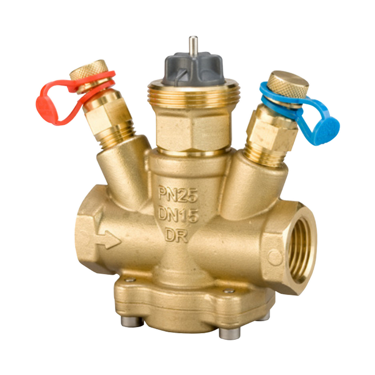
There are two ACU designs available; the most common will be a
normally closed design (part number 975 009 002 0) with one inlet
and one outlet. The second design is considered to be a normally
open design (part number 975 009 101 0) used on vehicles utilizing
a negative battery shut-off. This design will have two inlets and one
outlet. Figure 1.1.
Figure 1.1
How the ACU Works
The ACU is controlled by an ECU activated when the ECU sees an
ignition-controlled power supply. With the ignition key in the on or
run position, vehicle voltage is supplied to the ACU activating the
solenoid to the open position which allows air pressure to flow
through the ACU. The valve will remain open until the ignition key is
turned to the off position. When the key is turned off, the SCR ECU
will pulse a signal to the ACU to pulse air pressure through the SCR
lines pushing out any remaining urea fluid to keep the injector and
lines clean. This function is important because urea can crystallize
and clog the lines and the injector if the urea is subjected to too high
of a temperature.
If the ACU were to not operate correctly or stop operating altogether,
the urea in the SCR system may be incorrectly injected into the
engine exhaust causing higher emissions. When emissions exceed
the specification for any reason, the SCR ECU will turn on a warning
light on the dash panel and reduce the engine output and vehicle
speed. If the emission system is not repaired, the ECU will further
reduce the engine output allowing the vehicle to move at low
speeds, effectively a “limp home mode”, in order to have the
emission system repaired.
Figure 1.1
4007993a
NORMALLY OPEN
975 009 101 0
NORMALLY CLOSED
975 009 002 0

1 Introduction
2Meritor WABCO Maintenance Manual MM-1012 (Issued 02-10)
Schematics
Figure 1.2
Figure 1.3
Figure 1.2
4007994a
UREA/AIR
MIXTURE
SENT TO
EXHAUST
PRIMARY
UREA
TANK
UREA
PUMP
UREA
DOSER
NORMALLY CLOSED CONFIGURATION
SECONDARYWET
AIR CONTROL
UNIT
Figure 1.3
4007995a
UREA/AIR
MIXTURE
SENT TO
EXHAUST
AIR CONTROL
UNIT
PRIMARY
UREA
TANK
UREA
PUMP
UREA
DOSER
NORMALLY OPEN CONFIGURATION
SECONDARYWET

2 Removal and Installation
3
Meritor WABCO Maintenance Manual MM-1012 (Issued 02-10)
2 Removal and Installation
Hazard Alert Messages
Read and observe all Warning and Caution hazard alert messages in
this publication. They provide information that can help prevent
serious personal injury, damage to components, or both.
WARNING
To prevent serious eye injury, always wear safe eye protection
when you perform vehicle maintenance or service.
Park the vehicle on a level surface. Block the wheels to
prevent the vehicle from moving. Support the vehicle with
safety stands. Do not work under a vehicle supported only by
jacks. Jacks can slip and fall over. Serious personal injury can
result.
Remove all pressure from the air system before you
disconnect any component. Pressurized air can cause serious
personal injury.
Replacement Requirements
Any time a new ACU is installed, replace the oil desiccant cartridge
to ensure a clean air supply to the new part. When you drain the air
tanks before servicing the ACU, check for water or oil that may have
accumulated in the tanks. Water or oil in the air tanks could indicate
a problem with the air dryer or compressor contributing to the ACU
problem.
The air control unit can be found in the following locations
depending on the vehicle. Figure 2.1, Figure 2.2, Figure 2.3 and
Figure 2.4.
Figure 2.1
Figure 2.2
Figure 2.3
Figure 2.4
Figure 2.1
4007996a
WESTERN STAR, ALL MODELS
The ACU is
located under
the lower flange
of the left side
frame rail
behind the cab.
Figure 2.2
Figure 2.3
Figure 2.4
4007997a
24U MODELS, DUAL EXHAUST
The ACU is
located between
the flanges of the
left side frame
rail behind the
cab.
4007998a
The ACU is
located at the
top of the
frame
crossmember
to the right
of the cab
rear air
suspension.
3-PC. DAY CAB, 5-PC. SLEEPER CAB
4007999a
The ACU is located
near the right side frame
rail between the vertical
muffler and muffler
support.
3-PC. 2V2 UPRIGHT EXHAUST

2 Removal and Installation
4Meritor WABCO Maintenance Manual MM-1012 (Issued 02-10)
General Requirements
앫Mount the air control unit so that there is no direct splash or
spray from a wheel.
앫Keep the air control unit at least 12 inches (305 mm) from any
heat producing sources like exhaust manifolds or pipes,
transmissions, etc.
앫Line sizing from and to the air control unit should be at least
1/4 inch (6.35 mm).
앫Make sure there are no valves or other devices in the air supply
line to the air control unit.
Replacement Procedures
ACU Replacement
If there is a problem with the ACU functioning correctly, replace the
entire valve. Do not attempt to service or repair the valve. Refer to
Limited Warranty Document TP-1011 for warranty information.
ACU Removal
1. Remove the air lines to and from the ACU.
2. Remove the electrical harness from the ACU.
3. Remove the two fasteners and remove the ACU.
4. Remove the threaded hose fittings from the removed ACU.
ACU Installation
1. Install the threaded hose fittings removed from the old ACU
onto the new ACU.
2. Using two new fasteners, bolt the ACU to the bracket and
tighten the fasteners to 11 ft-lb (15 N폷m). @
3. Verify the removed air lines are clean and then connect them to
the new ACU.
4. Connect the vehicle electrical harness to the ACU.

3 Troubleshooting
5
Meritor WABCO Maintenance Manual MM-1012 (Issued 02-10)
3 Troubleshooting
Oil and Other Contaminants
The air control unit does not require maintenance. However, the ACU
can be affected by oil and other contaminants suspended in the air
as an aerosol. When these contaminants flow through the ACU, it
can cause the O-rings and rubber components to swell, affecting
the ability of the ACU to correctly control the air pressure.
Contaminants can also pass through the ACU and contaminate the
urea dosing system.
To prevent contaminants from reaching the ACU, an oil coalescing
device must be installed between the air compressor and the air
control unit. Either an air dryer with an integrated coalescing
desiccant cartridge or a standalone oil coalescing device is required.
Follow correct maintenance procedures and intervals for the oil
coalescing device used. If you do not use an oil coalescing device,
you will void any and all warranties provided on the ACU.
ACU Replacement
If there is a problem with the ACU functioning correctly, replace the
entire valve. Do not attempt to service or repair the valve. Refer to
Limited Warranty Document TP-1011 for warranty information.
Diagnostics
Condition Possible Cause Solution
ACU does not deliver air. There is no voltage to the ACU. Check the vehicle fuse/power supply.
The ACU solenoid is not operating. Replace the ACU.
The check valve is stuck in the closed
position.
Replace the ACU.
Air pressure delivered to the SCR dosing unit
is too high or too low.
The pressure limiting portion of the ACU is not
functioning.
Replace the ACU.

4 Specifications
6Meritor WABCO Maintenance Manual MM-1012 (Issued 02-10)
4 Specifications
General Requirements
앫Mount the air control unit so that there is no direct splash or
spray from a wheel.
앫Keep the air control unit at least 12 inches (305 mm) from any
heat producing sources like exhaust manifolds or pipes,
transmissions, etc.
앫Line sizing from and to the air control unit should be at least
1/4 inch (6.35 mm).
앫Make sure there are no valves or other devices in the air supply
line to the air control unit.
Operating Environment Requirements
Operating Parameter Requirement
Temperature (ambient operating range) –40°F to 175°F
(–40°C to 80°C)
Electrical Power 12 +/−3V DC
Minimum Inlet Pressure 87 psi (6 bar)
Maximum Working Pressure 145 psi (10 bar)
Installed Position No Restriction

Meritor WABCO Vehicle Control Systems
2135 West Maple Road Printed in USA
Troy, MI 48084-7121
800-535-5560 Copyright 2010 Issued 02-10
meritorwabco.com ArvinMeritor, Inc. Maintenance Manual MM-1012 (16579/22882)
Table of contents
