TECOM TS0820 Assembly instructions

© 2014 UTC Fire & Security Australia Pty Ltd. All rights reserved. 1 / 2 P/N MAINST-TS1021 • REV 03 • ISS 08AUG14
Eight-Input Expansion Module Installation Sheet
Description
Eight-Input Expansion Modules add eight inputs to TS0820,
TS0824, TS0866 and TS1020 DGPs.
This Installation Sheet applies to models TS0021 and TS1021
expansion modules:
•TS0021 expansion modules (green PCB) may be used
with Challenger10-series TS1020 Analogue DGPs, and
with Challenger V8-series TS0820, TS0824, and
TS0866 Data Gathering Panels (DGPs).
•TS1021 expansion modules (blue PCB) may be used with
Challenger10-series TS1020 Analogue DGPs.
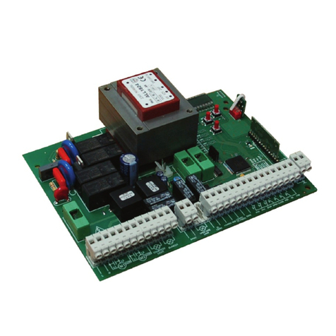
Figure 1: Eight-Input Expansion Module
1. Configuration DIP switch
2. J2 connector for ten-way cable from DGP or from previous
expansion module
3. J3 connector for ten-way cable to next expansion module
4. Input terminals
Expansion modules have a pair of ten-way connectors, and
one cable. One module can be plugged into a DGP’s J7
connector, and two additional modules can be daisy-chained to
the first, subject to the following:
•TS0820, TS0824, and TS1020 DGPs have eight onboard
inputs. Up to three expansion modules can be daisy-
chained to increase the quantity of inputs to 32.
•TS0866 Intelligent 4-Door Controllers have eight onboard
inputs. One TS0021 module can be used to increase the
quantity of inputs to 16.
The added inputs are numbered according to “Input
numbering” on page 2.
Product contents
Quantity
Item
1
Eight-Input Expansion Module with ten-way cable
1
Installation Sheet
1
Ring terminal
4
Three-way plug-on screw terminal connectors
5
M3 x 10 mm pan head screws
4
PCB standoffs
18
10 kΩ 1/4 W resistors
Inspect the package and contents for visible damage. If any
components are damaged or missing, do not use the unit;
contact the supplier immediately. If you need to return the unit,
you must ship it in the original box.
Installation
Expansion modules are mounted on standoffs (supplied) using
M3 x 10 mm pan head screws (supplied) inside the DGP
enclosure. The PCB is size B.
NOTICE! A qualified service person, complying with all
applicable codes, should perform all required hardware
installation.
To install the module:
1. Disconnect the plug pack and battery from the DGP.
2. Insert four standoffs (supplied) into the DGP enclosure at
a location suitable for the ten-way cable to connect the
expansion module to the DGP, or other expansion
module, as needed.
3. Slide the board’s terminal connectors together and mount
on the board.
4. Use four M3 x 10 pan head screws to fix the module to the
standoffs.
5. Connect the ten-way cable to the J2 connector on the
expansion module.
6. Connect the ten-way cable to the J7 connector on the
DGP, or other expansion module, as needed.
7. Connect the required input cables to the input terminals.
See “Input wiring” on page 2.
8. Configure the expansion module’s three-segment DIP
switch, and (if applicable) the DGP’s DIP switch (see
“Configuration settings” on page 2).
9. Reapply power to the DGP.

2 / 2 P/N MAINST-TS1021 • REV 03 • ISS 08AUG14
Configuration settings
Configure the module’s position in relation to the DGP using
the three-segment DIP switch (Figure 1 on page 1, item 1).
Table 1: DIP switch settings
Module position
SW1 SW2 SW3
First
(connected to the DGP) I OO
Second*
OI O
Third*
OOI
Legend: I = ON, O = OF
F
* If more than one expansion module is connected to a DGP,
then segment 5 in the DGP’s eight-segment DIP switch must
be set to ON.
Input wiring
By default, the Challenger system can monitor inputs for four
states (sealed, unsealed, open circuit, and short circuit). This is
accomplished by using two 10 kΩ end-of-line (EOL) resistors in
each input circuit.
Notes:
•The TS1020 DGP’s onboard inputs (and inputs connected
via TS1021 Eight-Input Expansion Modules) may be
configured to use a different EOL resistor value (not 10
kΩ), in which case you must use resistors of appropriate
value in each input circuit.
•TS0021 Eight-Input Expansion Modules do not support
1K0, 1K5 or 2K0 EOL values.
To use two-state monitoring for all inputs, Input Tamper
Monitoring must be set to No (Install menu option 7, System
Options).
See Challenger Installation and Quick Programming Manual
for details about wiring four-state and two-state monitored input
circuits.
Install EOL resistors in input circuits at the end of the circuit. If
an alarm device is connected, place the EOL resistors at the
device’s connections. If an input is not used, you don’t need to
connect an EOL resistor if you program the corresponding
input number as type 10 (spare).
Tip: Use sleeves on the resistor leads to prevent accidental
shorting.
Input numbering
Challenger input numbers are assigned according to Table 1
below.
Table 2: Challenger10 and Challenger V8 input numbers
Panel or DGP V10 inputs V8 inputs
Challenger panel 1 to 16 1 to 16
LAN 1, DGP 1 17 to 48 17 to 32 (or 48*)
LAN 1, DGP 2 49 to 80 33 to 48 (or 64*)
LAN 1, DGP 3 81 to 112 49 to 64 (or 80*)
LAN 1, DGP 4 113 to 144 65 to 80 (or 96*)
LAN 1, DGP 5 145 to 176 81 to 96 (or 112*)
LAN 1, DGP 6 177 to 208 97 to 112 (or 128*)
LAN 1, DGP 7 209 to 240 113 to 128 (or 144*)
Panel or DGP
V10 inputs
V8 inputs
LAN 1, DGP 8 241 to 272 129 to 144 (or 160*)
LAN 1, DGP 9 273 to 304 145 to 160 (or 176*)
LAN 1, DGP 10 305 to 336 161 to 176 (or 192*)
LAN 1, DGP 11 337 to 368 177 to 192 (or 208*)
LAN 1, DGP 12 369 to 400 193 to 208 (or 224*)
LAN 1, DGP 13 401 to 432 209 to 224 (or 240*)
LAN 1, DGP 14 433 to 464 225 to 240 (or 256*)
LAN 1, DGP 15 465 to 496 241 to 256
LAN 2, DGP 17 497 to 528 N/A
LAN 2, DGP 18 529 to 560 N/A
LAN 2, DGP 19 561 to 592 N/A
LAN 2, DGP 20 593 to 624 N/A
LAN 2, DGP 21 625 to 656 N/A
LAN 2, DGP 22 657 to 688 N/A
LAN 2, DGP 23 689 to 720 N/A
LAN 2, DGP 24 721 to 752 N/A
LAN 2, DGP 25 753 to 784 N/A
LAN 2, DGP 26 785 to 816 N/A
LAN 2, DGP 27 817 to 848 N/A
LAN 2, DGP 28 849 to 880 N/A
LAN 2, DGP 29 881 to 912 N/A
LAN 2, DGP 30 913 to 944 N/A
LAN 2, DGP 31 945 to 976 N/A
LAN 2, DGP 32 977 to 1008 N/A
* A Challenger V8 DGP address with more than 16 inputs makes
the next DGP address unusable.
Regulatory information
Manufacturer
UTC Fire & Security Australia Pty Ltd
t/a Interlogix
A UTC Building & Industrial Systems company
Level 1, 271–273 Wellington Road, Mulgrave,
VIC, 3170, Australia
Year of
manufacture
The first two digits of the product serial number
(located on the product identification label) are
the year of manufacture.
Compliance
N4131
NOTICE! This is a Class A product. In a domestic environment this
product may cause radio interference in which case the user may be
required to take adequate measures.
Disclaimer
The customer is responsible for testing and determining the
suitability of this product for specific applications. In no event is
UTC Fire & Security Australia Pty Ltd (trading as Interlogix)
responsible or liable for any damages incurred by the buyer or
any third party arising from its use, or their inability to use the
product.
Contact information
For contact information, see www.interlogix.com.au.
This manual suits for next models
3
Other TECOM Control Unit manuals
Popular Control Unit manuals by other brands
Toro
Toro EZ-Flo Plus EZF-29-03 Installation and operating instructions
Allen-Bradley
Allen-Bradley ControlNet FLEX Ex 1797-BCNR installation instructions

IRT Communications
IRT Communications IRT-6630-DDT user manual
Ebyte
Ebyte EA01-S user manual
Honeywell
Honeywell S7800A1167 manual
TATAREK
TATAREK RT-08G-BUF user manual
