Merkur SSM-6 User manual
1
SSM-6
Programmable Electronic Servomotor

2
CONTENTS Page

3
Merkür SSM-6 Introductory information ……………………………………………………. 5
Intended use of the SSM-6 Motor - Target group of the manual …………….. 6
Copyright –Disclaimer notice …………………………………………………………..
Commitment and warranty –Important Notes …………………………………………. 7
Standards ……………………………………………………………………………………………………. 8
Example of function selection - Credential example …………………………………. 9
Selection guide …………………………………………………………………………………………… 10
Servo motor sizes ……………………………………………………………………………………….. 11
Technical Information ……………………………………………………………………………....... 12
Common properties of SSM-6 Motors –Warnings at setup ………………………. 13
Setup and electrical installation ………………………………………………………………….. 14
Introduction to the electrical connection terminal ………………………………………. 15
Standard electrical connection ……………………………………………………………………. 16
Electrical installation, points to consider ……………………………………………………. 17
Operation system of motors: ON –OFF Operating …………………………………… 18
TPSC Operation (Floating Control) ……………………………………………………………… 19
Selectable Functions for ON-OFF and TPSC –Password Entry ……………………. 20
Standard password entry ………………………………………………………………………………. 20
How to use the standard password menu …………………………………………………….. 21
Menu for the creation of a new password …………………………………………………….. 21
Menu for changing motor direction ………………………………………………………………. 22
Minimum and maximum angle settings ……………………………………………………….. 23
Menu for programmable ignition output ………………………………………………………. 24
Menu for error assignment to contacts ………………………………………………………. 25
Retrospective error menu …………………………………………………………………………... 26
Menu for MANUAL operation of motors ……………………………………………………… 27
Analog operation system and bottom switch settings ………………………………. 28
Analog Operation and Output Curves –Analog output setting …………………… 29
Analog output limitation menu of the motor - Analog Configuration ………….. 30
Analog input change menu –Analog Input Menu …………………………………………31
Analog input change menu –Analog Output Menu …………………………………….. 32
Analog filter time setting menu ……………………………………………………………… 33

4
CONTENTS Page
Modbus operating system …………………………………………………………………………….. 34
Sample Modbus Connection …………………………………………………………………………… 35
Modbus communication speed selection …………………………………………………….…. 36
Modbus address menu –Tablet and Mobile Phone Address Menu ……………... 37
Hand terminal access menu ………………………………………………………………………….. 38
First start-up for SSM… motors ……………………………………………………………………. 39
Explanation of function menus …………………………………………………………………... 40
Explanation of function menus …………………………………………………………………... 41
Explanation of function menus ……………………………………………………………….….. 42
Explanation of function menus ……………………………………………………………..…….. 43
Explanation of function menus …………………………………………………………………….. 44
Explanation of function menus …………………………………………………………………….. 45
Menu of All Functions………………………………………………………………………………..……. 46
Menu of All Functions …………………………………………………………………………..………… 47

5
Merkür SSM-6
Programmable Electronic Servomotor
* Three separate operating systems in a single model
* Direct or remote control feature
* Advanced control system
* Modern technology rather than classical parts
* Need-based programmable functions
* Instant and retrospective error message
* Modbus communication in all versions
* Bluetooth communication
* Angle and control information on 1.6" display
* Chrome + 3 layers of electrostatic paint to casing
* AISI 304 Drive shaft and cover screws
* High protection class
* Analog filter, adjustable between 0 and 5 seconds
* 100% duty cycle
* Analog –Three positions –On-Off Control
* ± 0.25 < Position error
Intended use of SSM-6 Servo motors:
SSM-6 motors are designed especially for use in industrial burning plants. They are also used in
applications requiring precise controlled rotational movements between 0° and 90°.
The SSM-6 can be used in the following working situations: processes under harsh conditions, areas
that are difficult to control closely, sensitive enterprises in which mechanical faults will lead to
damage, heating systems, modulating valves, ball valves, butterfly valves, dampers and other devices
to be controlled for the arrangement of liquids.
Target group of the manual:
This manual is intended for the use of the engineers and technicians who will install and work with this
product. These persons are expected to have prior experience with such equipment.

6
Copyright:
The production and brand rights of Merkür Servo motors are owned by ERA LTD, as of 2015. All rights
are reserved throughout Turkey. This publication is protected by legal regulations and it is forbidden
to copy, distribute, publish, adapt or translate into any human or computer language this document in
any manner whatsoever without the written consent of ERA LTD.
Disclaimer notice:
In accordance with ERA LTD.’s continuous product development policy, the product presented in this
document may be modified without any obligation to give notice.
The materials in this document are prepared according to international standards, under which the
product is deemed sufficient in terms of its intended use. If used for purposes other than those
mentioned herein, it is necessary to obtain conformity and validation approval.
ERA LTD guarantees that SSM-6 smart type servo motors under the brand of Merkür do not infringe
the patent of any product within the same category and functionality, in the territory of the Republic
of Turkey.
When preparing this manual, care was taken to make it as faultless and complete as possible. If you
come across any faults or omissions, please share them with us and we will correct them. In this way,
we hope to improve the documentation of our product for the benefit of our customers. Please send
will help in the development of the SSM-6 Model Smart Servo motor, which is unique in its category.
Commitment and warranty :
SSM-6 Servo motors produced under the brand of MERKÜR are under the responsibility of Era
Industrial Relay Manufacturing Industry and Trade Limited Company, as the manufacturer. The
obligations of ERA LTD related to MERKÜR-branded servo motors are limited to the supply of spare
parts required for the servo motor, whether due to a warranty violation or negligence. In this regard,
ERA LTD shall not be responsible of liable for any damages incurred through the purchase, installation
or failure during use of its products, be it indirect, special, incidental or consequential, including, but
not limited to, damage to any products, loss of use, other expenses or losses.
* All functions of MERKÜR motors are tested before being offered for sale.
Final functional tests should be performed by qualified personnel within the installed system.
* ERA LTD will accept possible manufacturing faults after conducting a technical inspection, but will
accept no responsibility for any subsequent damage.
*Improper opening of the SSM-6 motor may cause a fault. ERA LTD is not responsible for electrical
or mechanical faults that occur during installation.

7
Important Notes :
* First of all, identify the information on the outer label of your SSM-6 Servo motor.
Compare the type number on the label with the selection table on page 6, and
get to know your motor.
* Read this manual carefully before installation. Make sure that you understood the
contents of the manual.
* You should definitely obey all rules. Do not disregard the warnings or implementation limits
given in this manual without the written consent of ERA LTD.
* Do not continue if there is a section you do not understand in this manual. Contact the
technical department for MERKÜR motors. The contact address is as follows.
Standards :
Product Brand : MERKÜR
Registration No : 2015-33881
ICAM Model : SSM-6
Test Date : 20.09.2016
Report No : LVT.D-16 - 0910 - R0
LVT.D-16 - 0813 - R02
Testing Institution : LVT Test Laboratories (Kiva -Meyer)
EU Directives : 2014/35/EU - LVD
2014/30 /EU –EMC
Standards : TS EN 61000-6-1:2011
TS EN 61000-6-3:2007/A1:2011
Certificates : Rosh - CE - Utility Model
Basic Standards : TS EN 61000-4-2
TS EN 61000-4-4
TS EN 61000-4-5
TS EN 61000-4-6

8
Preliminary information for function selection in SSM-6 Motors:
As seen in the selection guide in Figure 1, there are 8 Sections in the guide. In order to
determine the operating system of the SSM-6 servo motor, the tables for which choices should be
made are as follows.
1 –Supply Voltage 2 –Rotation time
3 –Direction of rotation 4 –Control Input
5 –Analog Feedback Output 6 –Digital Input
7 –Feedback potentiometer Output 8 –Accessories
The features are listed in the selection guide in tables 1 to 7. Only one feature is
selectable from this list. In addition to the selected features, all features in the Accessories section
in table 8 can be selected.
The Digital Input in Table 6 does not work together with 3P or OC in Table 4.
The marked tables in the selection guide are free of charge. ( Figure 2 )
The functions indicated in the empty tables in the selection guide are to be charged.
Credentials of the SSM-6 servo motor:
An example of the function selection in SSM-6 motors and related explanations are as follows.
Please refer to the selection guide and review the details of the motor order.
Figure 1 : Example of SSM-6 Selection
A1 : Supply voltage 24 VAC/DC
3 : Rotation time and torque 30 s. 90° 20 NM.
1 : Counterclockwise (CCW), when looking from the shaft
01 : Control Input 4-20 mA. (İnput)
01 : Feedback Output 4-20 mA.
DI : Digital Input
R1 : Feed Back Potentiometer 1 Kohm.
BT : Bluetooth module for remote control
R : 11 mm. IP 68 Metallic Union (3 Pcs)
MERKÜR SSM - 6 A1 3 1 01 01 DI R1 BT R
CAUTION
WARNING

9
SSM-6 MOTOR SELECTION GUIDE
Figure 2 : Selection Guide
Özellikler Seçim Kriterleri
MERKÜR SSM - 6 Fiyat
Besleme Voltajı (1)
24 V.AC/DC - 50 / 60 Hz. A1
115 / 230 VAC. 50 / 60 Hz. B1
90º Dönme Süresi (2)
30 Saniye 20 NM. Tork 3
60 Saniye 40 NM. Tork 6
Dönüş Yönü (3)
CCW ( Milden bakınca saat yönünün tersi) 1
CW ( Milden bakınca saat yönü ) 2
Kontrol Sinyali ( INPUT ) (4)
4 - 20 mA. 01
0 - 20 mA. 02
2 - 10 VDC. 21
0 - 10 VDC. 10
TPSC ( Yüzer Kontrol ) 3P
ON - OFF ( AÇ - KAPA ) OC
Modbus MB
Analog Feed Back Çıkışı ( OUTPUT ) (5)
İstenmiyor 00
4 - 20 mA. 01
0 - 20 mA. 02
2 - 10 VDC. 21
0 - 10 VDC. 10
Digital input (6)
İstenmiyor 00
DI CTRL (Harici digital girişle çalışma prensibi ) DI
Feedback Potansiyometre (7)
İstenmiyor 00
1 kOhm. R1
2,5 kOhm. R2
Aksesuarlar (8)
İstenmiyor 00
Bluetooth Modül (Uzaktan Kumanda için) BT
11 mm. IP 68 Metal Rakor (3 Adet) R
8 mm. Çapında Yuvarlak motor şaftı S2
Tablet (Windows Tabanlı) TB
Specifications
Selection Criteria
Price
Supply Voltage (1)
Rotation time
Second
Second
Torque
Torque
Direction of rotation
CCW(Counterclockwise viewed from the shaft)
CW (Clockwise viewed from the shaft)
Control Signal
viewed from the
(Floating Control)
Analog Feedback Output
shaft)
Not Requested
Not Requested
Feedback Potentiometer
Not Requested
Accessories
Not Requested
Bluetooth module (for remote control)
Metallic Union (3 Pcs)
Diameter Round Motor Shaft
(with Windows operating system)

10
DIMENSIONS OF SSM-6 SERVOMOTORS
Dimensions : mm.
Figure 3 : Motor Sizes
TOP VIEW
BOTTOM VIEW
REAR VIEW
RAKOR
SIDE VIEW
DETAIL:D1
SCALE 1 : 1.3
Section

11
Technical Information for SSM-6 Servomotors :
Mode of Operation : Programmable Electronic Servomotor
Servo motor type : A - ON/OFF C –ANALOG
B - TPSC D - MODBUS
Standard Control Signal : (0) 4–20 mA. (250 Ohm.), (0) 2-10 VDC.
Communication system : Modbus Operating (9600–19200-57600-115200 Boud )
Double register format FP L - Little Endian
(1,2,3,4) Read Code (hex=64, Decimal=100
Register data type: unsigned 16
Communication system: (Option) * : Bluetooth (2.4 Ghz. Communication frequency)
Low operating voltage : 24 Volt AC. / DC. ± %5 Volt. 320 mA.
High operating voltage: (Option)* : 100-240 VAC. 50/60 Hz. 7 VA.
Duty Cycle : 100 %
Motor’s Direction of Rotation : CW or CCW (When observed from the motor’s shaft)
Angle of rotation : 0-90°
Position Error : ± 0.25°
Motor setting range : At 1° increments
External casing : Chrome + 3 layers electrostatic painted aluminum
Drive shaft : AISI 304 (Stainless Steel)
Position indicator : Electronic (1.6 inch liquid crystal blue display)
External switch : 2 programmable relay ignition 1 Amp. Max.
Rotation time : 30 seconds 90°
Operating Torque : 30 seconds 90° =20 Nm. 60 seconds 90°= Max. 40 Nm.
Feedback signal : 1 (Option) * : (0) 4–20 mA. (0) 2-10 VDC. Galvanic isolation Feedback
signal : 2 (Option) * : 1K.... 5 K. Linear potentiometer
Protection class : IP 65
Analog filtering : Between 0 and 5 seconds
Position of installation : Horizontal/Vertical
Cable connection terminal : 16 x 1.5
Motor limit control : Micro switch + Electronic limitation
Weight (without packaging) : 3.5 Kg.
Operable ambient temperature : -10 to +60°C
*The modules included in the options can operate in all SSM-6 motor models. The
desired models should be specified in the initial order.

12
Common properties of SSM-6 Servo motors:
•Digital angle indicator,
•Locking settings with user password,
•Retrospective error information for 10 different operating systems,
•Programming through buttons on the motor,
•Possibility to set between 0° and 90° at 1° increments,
•Manual control through buttons on the motor,
•Motor’s direction of rotation settable as CW or CCW,
Setup and mechanical installation :
Do not apply any thermal insulation to the servo motor!
Install in a vertical or horizontal position. Do not install upside down!
Before installation, check the conformity of the power of the motor to the working area!
Check that the connecting rods and joints are compatible with the motor’s output shaft!
If the servo motor is to be installed directly, suitable screws must be used. Using the wrong
screw may damage the product. Refer to Figure 3 for screw sizes.
Do not attempt to install by hitting or forcing the motor shaft!
SSM-6 motors should have gapless interconnecting fittings to maintain position sensitivity
and make this feature useful!
Make sure that cable inputs are compatible, and have not been modified or altered in any
way.
3 x PG9 waterproof plastic unions are supplied with SSM-6 motors, and can be found in the
packing box. The cable entry holes to the motor are temporarily closed with a plastic plug.
Do not remove the plugs unnecessarily! Always connect only the supplied PG9 unions to
the cable entry points after removing the plugs!
If there is no suitable o-ring in the union or the appropriate cable is not installed, the
protection class of the SSM-6 servo motor becomes void, as the negative effects of
moisture, dust, water, etc. entering the motor may cause faults!
CAUTION
13
Setup and electrical installation:
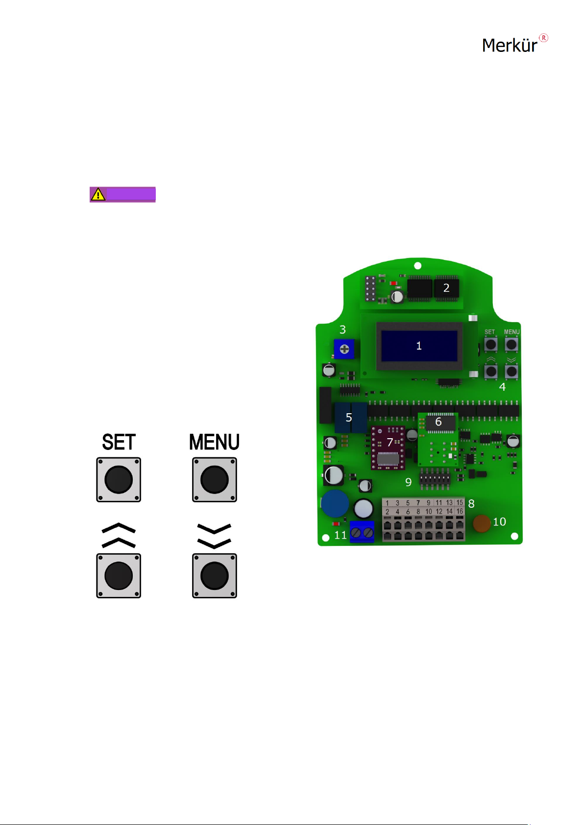
A -Introduction to PCB board and program buttons:
The first startup should be performed only by experts!
1 : Display
2 : Bluetooth Module (Option)
3 : Display brightness setting pot
4 : Program buttons
5 : Programmable output relays
6 : Analog output module (Option)
7 : Step motor drive
8 : Connection clamp
9 : Bottom switch block
10 : 1.6 Amp. Fuse
11 : Voltage input
Figure 5 : Image of the PCB of SSM-
6
Figure 4 : Program buttons of SSM-6
SET : Program Set Button
MENU : Program Entry Button
UP : Increase Button
DOWN : Decrease Button
WARNING
14
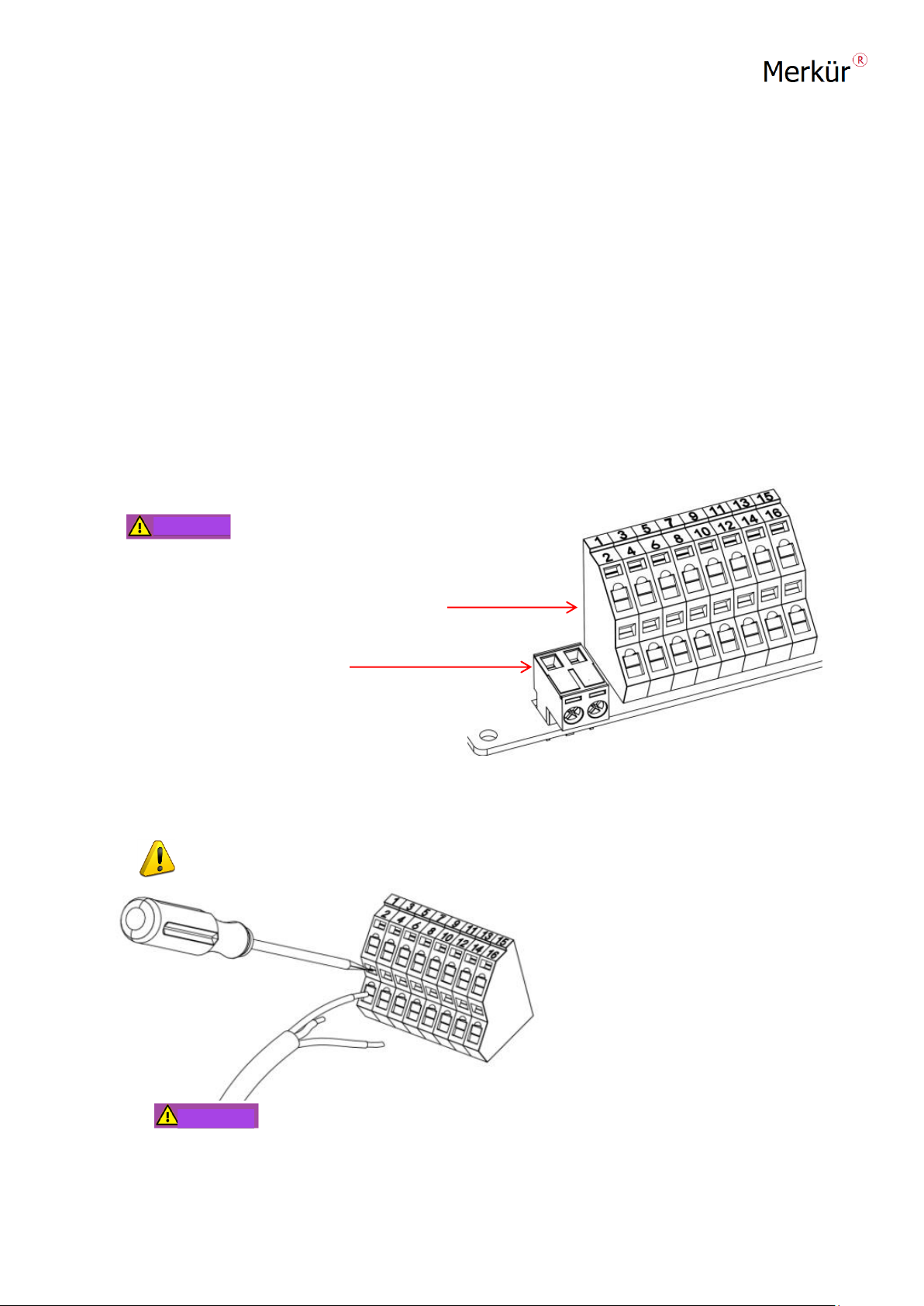
B -Introduction to the Electrical Connection Terminal
As standard, SSM-6 motors are provided with a voltage of 24 VAC/DC.
The supply voltage input is separate from the block clamps, as is seen in Figure 6.
In motors with 24 VAC/DC input, the voltage input terminal block is BLUE.
For 110-220 volt motors, the block is GREEN. The terminal block, containing 16 inputs, is a
spring-weighted double-deck connector.
Odd numbered terminals are on the upper row; (1-3-5-7- 9-11-13-15)
Even numbered terminals are on the lower row; (2-4-6-8-10-12-14-16)
Clamps no. 1 and 2 are
used for internal installation;
Please do not remove!
Control Inputs
Supply voltage input
Blue Colored Terminal : 24 VAC/DC
Green Colored Terminal : 110-220 VAC Figure 6 : Electrical connection terminal
Clamp cable sockets 2.5 mm.
When making cable connections, first
open the connection socket by
inserting an appropriate screwdriver.
After placing the cable in the
terminal, remove the screwdriver.
The cable socket will close
automatically.
After completing the connection, check the cable has been properly
installed in the connection terminal!
WARNING
WARNING

15
SSM-6 STANDARD ELECTRICAL CONNECTION
(For All Functions)
Figure 7 :General electrical connection for SSM-6 Motors
1 - Internal Connection 10 - Digital Output 1 NA Contact
2 - Internal Connection 11 - Digital Output 2 NA Contact
3 - TPSC input left turn 12 - Modbus communication +
4 - TPSC input right turn 13 - Modbus communication -
5 -TPSC 24 VDC. Output 14 - Feedback output left
6 - (GND) Common output 15 - Feedback output right
7 - Current or Voltage Input + 16 - Feedback central output
8 - Current or Voltage Output –17 - (L) 24 VAC/DC. +
9 - Digital input central contact 18 - (N) 24 VAC/DC.–

16
Points to consider during the electrical installation of SSM-6 Motors :
•Before the installation, make sure that the power to any other equipment connected to the
motor is completely turned off!
• Ensure that the electrical installation is carried out by experience people!
• Make the electrical connection only after carefully reviewing the motor ID!
•Make the electrical installation in compliance with legal regulations!
•Use screened cables for low voltages!
• Connecting the ground cable is vital!
• If the label on the casing is worn, refer to the label under the motor cover.
SSM-6 Servo motors are typically manufactured and offered for sale with a supply
voltage of 24 Volts AC/DC.
If the user desires to operate the equipment at a higher voltage, 110/220 VAC should be specified
when placing the order. See Figure-2, selection guide. If you should later decide to change the
supply voltage for any reason, you should contact our company.
The voltage input terminal of the SSM-6 motors operating at 24 Volts is Blue colored. See Figure 8
The inputs of terminals 17 and 18 are live end (L+) and (N-) respectively.
If the SSM-6 motor operates at a higher voltage (110-220 VAC.), the terminal will be green. In
such cases, the connection shown in Figure 9 should be applied. Terminal 17 is Phase (Live end)
and terminal 18 is Neutral.
Figure 8 : 24 Volt.AC/DC Figure 9 : 110/220 Volt AC.
Electrical connection Electrical connection
17
Operating system of SSM-6 motors:
A - ON/OFF
B - TPSC
C –ANALOG
D- MODBUS
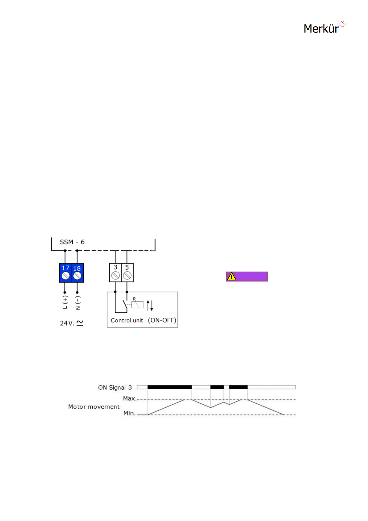
A -ON/OFF OPERATING SYSTEM : Aside from the constant power supplied
to the servo motor, the motor moves in the direction of the ON position, towards the far end of
the ON position angle, as long as power is supplied from the control input. When deenergized, the
motor will turn back to the closing position. (This can be adjusted to any angle between 0°and 90°.)
The ON-OFF operation connection of the servo motor should be made as shown
in Figure 12. 24 VAC or 24 VDC voltage is supplied to terminals 17 and 18. When terminals 3
and 5 are combined with a contact, the motor moves in the opening direction, and when the
contact is made, it moves in the closing direction.
Do not apply any voltage to
terminals 3 and 5 of the ON-OFF
servomotors! Run according to the
connection diagram in Figure 9!
Figure 9 : ON-OFF control connection
Motion graph in ON-OFF controlled servo motors
WARNING

18
B -TPSC Operation System (Floating Control) :
A TPSC (Three Position Step Control or Floating Control) operates between the maximum and
minimum limits, based on the signal coming from the Digital inputs of the SSM-6 Servo motor.
The electrical and control connections must be made as shown in Figure 10. The supply voltage
enters from terminals 17 and 18. Terminal 5 is the central contact of the opening and closing
relays of the control unit to be used for the motor.
As shown in Figure 10, as long
as Contact R1 is connected to
terminal 3, the SSM-6 motor will
move in the opening direction, and
likewise, as long as the R2
contact is connected to terminal 4,
the SSM-6 motor will move in
the closing direction. If there
is no input from terminals 3 or 4,
the motor will remain in the last
motion position.
Figure 10 : TPSC Control connection in SSM-6 Motors
Motion graph in floating controlled servo motors

19
Selectable functions in ON-OFF and TPSC Motors :
The available functions on the SSM-6 Servo motors within the two operational
modes (ON-OFF and TPSC) are as follows.
a –Standard password entry –Creating a new password (to prevent settings from being changed)
b –Changing the direction of the Motor to CW (Clockwise) or CCW (Counterclockwise)
c–Minimum and maximum angle settings (Any angle between 0° and 90°)
d -Programmable two dry contact outputs (Error assignment menu)
e –Error assignment menu and the display of 10 retrospective errors,
f - Manual operation feature.
Make sure the device is correctly grounded before providing power the servo
Motor! When it is necessary to change or adjust the function, it is important to pay the necessary
attention to electrical hazards to prevent loss of life!
The standard password entry in all models of Merkür motors is as in Figure 11.
You must know your login password in order to enter the password settings menu. The default
password on SSM-6 servo motors is 1 2 3 4. You should follow the procedure in Figure 11 to enter
the password.
a - ) Standard Password Entry:
Figure 11 : Standard password entry
WARNING
WARNING

20
How to use the standard password menu;
1 - Press the MENU button: the -MENU SETTINGS- message will be displayed on the screen
2 - Press the SET button: the PASSWORD message will be displayed and password digits will flash
on the screen.
3 - Enter each number with the Up button and then press the SET button to save,
4 - Once you have entered the last number and pressed the SET button, you can return to the
main screen by either waiting for 60 seconds without pressing any buttons, or by pressing
the MENU button repeatedly until you reach the main screen.
New Password Menu : Creating a new password.
Figure 12 : Password Creation Menu
Table of contents
Popular Engine manuals by other brands

Motus
Motus MONOS Series Installation and use instructions and warnings

Continental Motors
Continental Motors C75 Instruction and service manual

Universal
Universal atomic four owner's manual

Detroit Diesel
Detroit Diesel DDFP Series Operation and maintenance instruction manual

SEW-Eurodrive
SEW-Eurodrive M1 N Series Assembly and operating instructions

BAFANG
BAFANG H610 manual


 instructions")