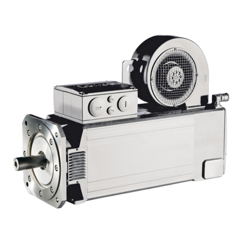
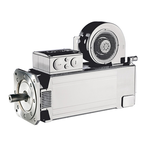
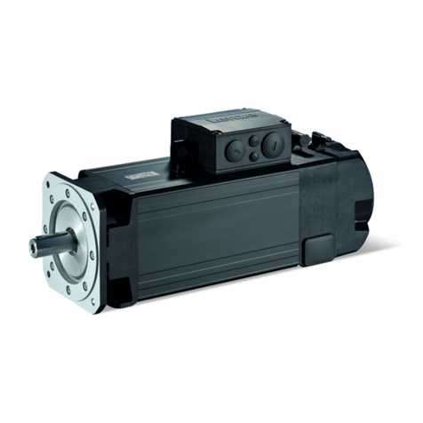
Lenze g500-B Technical manual

Geared servo motors
Bevel geared servo motor g500-B / m850
Project planning EN


Contents
About this document5
Document descripon 5
Further documents 5
Notaons and convenons 6
Product informaon 7
Product descripon 7
Idencaon of the products 8
Features 9
The modular system 10
Informaon on project planning 17
Safety instrucons 18
Basic safety instrucons 18
Applicaon as directed 18
Foreseeable misuse 18
Residual hazards 19
Drive dimensioning 21
Final conguraon 28
Environmental condions 28
Free spaces 30
Informaon on mechanical installaon 37
Important notes 37
Transport 37
Installaon 37
Informaon on electrical installaon 38
Important notes 38
Preparaon 38
Technical data 39
Notes regarding the given data 39
Standards and operang condions 40
Conformies/approvals 40
Protecon of persons and device protecon 40
EMC data 40
Environmental condions 40
Data overview 41
Radial forces and axial forces 49
Selecon tables 51
Inverter mains connecon 400 V, Self-venlated 52
Dimensions 78
Basic dimensions 78
Weights 103
Basic weights 103
Addional weights 103
Contents
3

Product extensions 104
Torque plates 104
Sha covers 109
Motor connecon 112
Connecon via ICN connector 112
Brakes 117
Spring-applied brakes 119
Feedback 121
Resolver 122
Absolute value encoder 123
Temperature monitoring 124
Thermal detectors PT1000 124
Product codes 125
Motor data 127
Rated data 127
Inverter mains connecon 400 V, Self-venlated 127
Torque characteriscs 129
Appendix 134
Good to know 134
Approvals/direcves 134
Operang modes of the motor 135
Enclosures 136
Contents
4

About this document
Document descripon
This document addresses to all persons who want to carry out any conguraons with the
products described.
The data and informaon compiled in this document serve to support you in the dimensioning
and selecon processes and in carrying out the electrical and mechanical installaon. You will
receive informaon regarding product extensions and accessories.
•The document includes safety instrucons which must be observed.
•All persons working on and with the drives must have the documentaon at hand during
work and observe the informaon and notes relevant for it.
•The documentaon must always be complete and in a perfectly readable state.
NOTICE
Please observe the notes in the following chapters!
▶Safety instrucons ^ 18
▶Informaon on mechanical installaon ^ 37
▶Informaon on electrical installaon ^ 38
Further documents
Informaon and tools with regard to the Lenze products can be found on the
Internet: hp://www.lenze.com à Download
About this document
Further documents
5

Notaons and convenons
This document uses the following convenons to disnguish dierent types of informaon:
Numeric notaon
Decimal separator Point The decimal point is always used.
Example: 1 234.56
Warning
UL warning UL Are used in English and French.
UR warning UR
Text
Engineering tools » « Soware
Example: »Engineer«, »EASY Starter«
Icons
Page reference ¶Reference to another page with addional informaon
Example: ¶ 16 = see page 16
Documentaon reference ,Reference to another documentaon with addional informaon
Example: , EDKxxx = see documentaon EDKxxx
Layout of the safety instrucons
DANGER!
Indicates an extremely hazardous situaon. Failure to comply with this instrucon will result
in severe irreparable injury and even death.
WARNING!
Indicates an extremely hazardous situaon. Failure to comply with this instrucon may result
in severe irreparable injury and even death.
CAUTION!
Indicates a hazardous situaon. Failure to comply with this instrucon may result in slight to
medium injury.
NOTICE
Indicates a material hazard. Failure to comply with this instrucon may result in material
damage.
About this document
Notaons and convenons
6

Product informaon
Product descripon
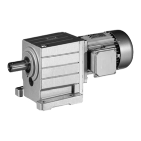
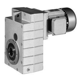
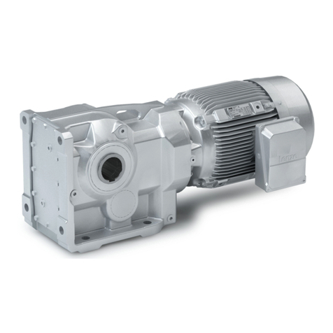
In combinaon with servo motors, our bevel gearboxes form a compact and powerful drive
unit. Numerous opons at the input and output end provide for the drive to be exactly
adapted to your applicaon.
The ecient bevel gearboxes feature high reliable radial forces, closely stepped gear
reducons and a low backlash. They are available in a 2-stage and 3-stage design with a
torque of up to 4300 Nm and a rao of up i= 360.
Designs
•High-ecient right-angle gearbox in a compact design for space-saving installaon
•Standardised sha and ange dimensions for an easy machine integraon
•Low backlash and high torsional sness provide for exact results in posioning
applicaons
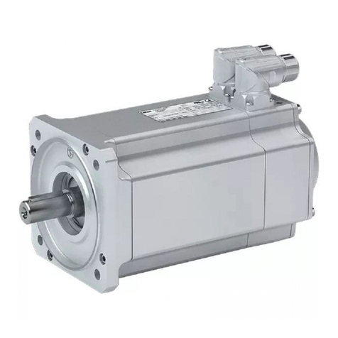
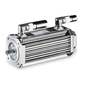
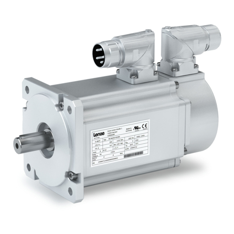
Synchronous servo motor m850 as basis for geared motor
In a power range of 2.0 to 9.2 kW, Lenze oers servo motors with an easily scalable modular
design.
The drives are designed for the open-loop or closed-loop controlled servo inverter operaon.
Medium dynamics and easy controllability via a favourable mass inera rao of the load to the
motor characterise these motors.
Customer benet
•Easy controllability by an advantageous rao of the mass inera of the load and that of the
motor
•High overload capacity of the motors
•Easy assembly and easy servicing thanks to connectors with bayonet catch and rotatable
connector boxes
•Reduced cabling thanks to one-cable technology in connecon with digital absolute value
encoders
•High eciency
•Space-saving thanks to compact direct aachment to Lenze gearboxes
•Can be used universally for a wide range of machine tasks due to the market-oriented
modular system
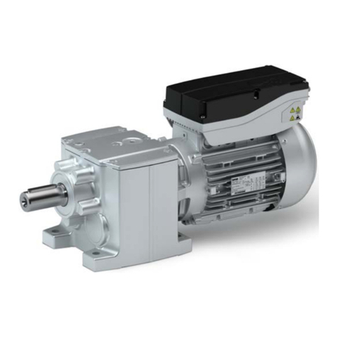
Synchronous servo motor m850-S120/L3960 - bevel gearbox g500-B450 Synchronous servo motor m850-S120/L3960 - bevel gearbox g500-B450
with one-cable technology in connecon with digital absolute value
encoder
Product informaon
Product descripon
7

Idencaon of the products
Gearbox product name
Gearbox type Product series Type Rated torque Nm Product
Bevel gearbox g500 - B
45 g500-B45
110 g500-B110
240 g500-B240
450 g500-B450
600 g500-B600
820 g500-B820
1500 g500-B1500
2700 g500-B2700
4300 g500-B4300
Product name of the motor
Product series Type Flange height Overall length Rated speed Motor
mm rpm
m850 - S (synchronous)
120
/
S (short) 3960 m850-S120/S3960
M (medium) 3960 m850-S120/M3960
L (long) 3960 m850-S120/L3960
140
S (short) 3240 m850-S140/S3240
M (medium) 3240 m850-S140/M3240
L (long) 3240 m850-S140/L3240
190
S (short) 3000 m850-S190/S3000
M (medium) 3000 m850-S190/M3000
L (long) 2520 m850-S190/L2520
Product informaon
Idencaon of the products
8

Features
Torque plate mounting
Output flange
Output shaft
Torque plate mounting
Housing type
(depending on the
mounting position)
Oil drain plug
(depending on the mounting position)
Remove oil control plug
Oil filler plug
(depending on the mounting position)
Ventilation Temperature monitoring
Spring-applied brake
Feedback
Motor connection
Cooling
Product informaon
Features
9

The modular system
Values printed in bold are standard designs. Values that are not printed in bold
are potenal extensions, some of them including a surcharge.
Geared motors up to 450 Nm
Gearboxes g500-B110 g500-B240 g500-B450
Min. motor assignment m850-S120 m850-S120 m850-S120
Max. motor assignment m850-S120 m850-S140 m850-S140
Technical data
Max. output torque Nm 100 140 210
Min. drive torque Nm 4.8 4.8 4.8
Max. drive torque Nm 7.4 14.0 17.4
Mounng posion
Standard A/B/C/D/E/F
Combined AEF
Colour Primed
Painted in RAL colours
Surface and corrosion protecon OKS-G
Dierent types of OKS
Output sha
Solid sha with featherkey (V) mm 20 x 40 30 x 60 30 x 60
Hollow sha with keyway (H) mm 20/25 30/35 35/40
Hollow sha with shrink disc (S) mm 20 30/35 35
Sha material Steel
Stainless steel
Sha sealing ring material NBR
FKM (Viton)
Output sha bearing Normal
Reinforced
Gearbox design With foot (HBR)/(VBR/SBR)
With foot and centring (HAR/VAR/SAR)
With foot and output ange (HAK/VAK/SAK)
Output ange (K) mm 120/160 160/200 200
Lubricant Synthec oil
Food-grade oil
Cooling Self-venlated
Torque support At threaded pitch circle
On the housing foot
Sha cover Hollow sha cover, hoseproof
Shrink disc cover
Motor connecon Connectors
Hybrid connector ICN for one-cable technology
Permanent magnet holding brake Without
With
Feedback Resolver
Absolute value encoder
Digital absolute value encoder for one-cable technology
Temperature monitoring Thermal detectors PT1000
Product informaon
The modular system
10
Geared motors from 600 Nm to 4300 Nm
Gearboxes g500-B600 g500-B820 g500-B1500 g500-B2700 g500-B4300
Min. motor assignment m850-S120 m850-S120 m850-S120 m850-S120 m850-S120
Max. motor assignment m850-S190 m850-S190 m850-S190 m850-S190 m850-S190
Technical data
Max. output torque Nm 600 820 1500 2700 4300
Min. drive torque Nm 4.8 4.8 4.8 4.8 4.8
Max. drive torque Nm 35.0 35.0 35.0 35.0 35.0
Mounng posion
Standard A/B/C/D/E/F
Combined
Colour Primed
Painted in RAL colours
Surface and corrosion protecon OKS-G
Dierent types of OKS
Output sha
Solid sha with featherkey (V) mm 35 x 70 35 x 70 50 x 100 60 x 120 80 x 160
Hollow sha with keyway (H) mm 40/45 40/45 50/55 60/70 70/80
Hollow sha with shrink disc (S) mm 40 40 50 65 75/80
Sha material Steel
Stainless steel
Sha sealing ring material NBR
FKM (Viton)
Output sha bearing Normal
Reinforced
Gearbox design With foot (HBR)/(VBR/SBR)
With foot and centring (HAR/VAR/SAR)
With foot and output ange (HAK/VAK/SAK)
Output ange mm 200/250 200/250 250/300 350 400/450
Lubricant Synthec oil
Food-grade oil
Cooling Self-venlated
Torque support At threaded pitch circle
On the housing foot
Sha covers Hollow sha cover, hoseproof
Shrink disc cover
Motor connecon Connectors
Hybrid connector ICN for one-cable technology
Permanent magnet holding brake Without
With
Feedback Resolver
Absolute value encoder
Digital absolute value encoder for one-cable technology
Temperature monitoring Thermal detectors PT1000
Product informaon
The modular system
11

Models at the output
NOTICE
Please observe the available gearbox designs!
Hollow sha, with foot
Without centring (HBR) With centring (HAR) Flange with through holes (HAK)
Hollow sha with shrink disc, with foot
Without centring (SBR) With centring (SAR) Flange with through holes (SAK)
Solid sha, with foot
Without centring (VBR) With centring (VAR) Flange with through holes (VAK)
Product informaon
The modular system
12

Models at the output
Motor connecon
ICN connector Hybrid connector ICN for one-cable
technology
Cooling: self-venlated
Feedback Feedback and brake
Product informaon
The modular system
13

Mounng posions
Geared motors
In the following graphics, the connector in posion 2 is colour-coded. If the
mounng posion (A … F) changes, the connector posions or terminal box
posions (2 … 5) are rotated accordingly.
To reduce the number of dierent versions, the gearboxes can also be ordered with combined
mounng posions:
•g500-B110 ... B450 in AEF mounng posion
A
B
C
D
F
E
Product informaon
The modular system
14

Connector/terminal box
The connector or terminal box posion (2 ... 5) must be given as a funcon of
the mounng posion.
2
4
5
3
Solid sha
Please specify the sha posion 3 or 5 when ordering.
3
5
Product informaon
The modular system
15

Shrink disc
Please specify the shrink disc posion 3 or 5 when ordering.
It is not possible to have the ange and the shrink disc in the same posion.
3
5
Flange
Please specify the ange posion 3 or 5 when ordering.
3
5
Product informaon
The modular system
16

Informaon on project planning
In order to carry out an accurate drive dimensioning process, you can use our conguring
soware, the »Drive Soluon Designer«.
With the» Drive Soluon Designer« you can carry out the drive dimensioning process quickly
and with top quality. The soware contains profound and proven experse with regard to
drive applicaons and mechatronic drive components.
Please refer to your competent Lenze sales company.
Informaon on project planning
17

Safety instrucons
Disregarding the following basic safety measures and safety informaon may lead to severe
personal injury and damage to property!
Observe all specicaons of the corresponding documentaon supplied. This is the
precondion for safe and trouble-free operaon and for obtaining the product features
specied.
Please observe the specic safety informaon in the other secons!
Basic safety instrucons
Personnel
The product must only be used by qualied personnel. IEC 60364 or CENELEC HD 384 dene
the skills of these persons:
•They are familiar with installing, mounng, commissioning, and operang the product.
•They have the corresponding qualicaons for their work.
•They know and can apply all regulaons for the prevenon of accidents, direcves, and
laws applicable at the place of use.
Process engineering
The procedural notes and circuit details described are only proposals. It is up to the user to
check whether they can be adapted to the parcular applicaons. Lenze does not take any
responsibility for the suitability of the procedures and circuit proposals described.
Applicaon as directed
•The product must only be actuated under the operang condions and power limits
specied in this documentaon.
•The product meets the protecon requirements of 2014/35/EU: Low-Voltage Direcve.
•The product is not a machine in terms of 2006/42/EU: Machinery Direcve.
•Commissioning or starng the operaon as directed of a machine with the product is not
permied unl it has been ensured that the machine meets the regulaons of the EC
Direcve 2006/42/EU: Machinery Direcve; observe EN 60204−1.
•Commissioning or starng operaon as directed is only permissible if the EMC Direcve
2014/30/EU is complied with.
•The product is not a household appliance, but is only designed as a component for
commercial or professional use in terms of EN 61000−3−2.
•The product can be used according to the technical data if drive systems have to comply
with categories according to EN 61800−3.
•In residenal areas, the product may cause EMC interferences. The operator is responsible
for taking interference suppression measures.
•Do not use the built-in brakes as fail-safe brakes. Disrupve factors that cannot be
inuenced may cause the braking torque to be reduced.
•The product must only be actuated with inverters.
Foreseeable misuse
•Actuate directly on the mains voltage
•Use in potenally explosive areas
•Use in aggressive environments
•Use under water
•Use under radiaon
•Use in generator mode
Informaon on project planning
Safety instrucons
Foreseeable misuse
18

Residual hazards
Even if notes given are taken into consideraon and protecve measures are implemented,
the occurrence of residual risks cannot be fully prevented.
The user must take the residual hazards menoned into consideraon in the risk assessment
for his/her machine/system.
If the above is disregarded, this can lead to severe injuries to persons and damage to
property!
Protecon of persons
•The product does not provide safety-related funcons.
-A higher-level safety system must be implemented.
-Addional monitoring and protecve equipment complying with the safety regulaons
applicable in each case must be used.
•The power terminals may carry voltage in the switched-o state or when the motor is
stopped.
-Before working, check whether all power terminals are deenergised.
•Voltages may occur on the drive components (e.g. capacive, caused by inverter supply).
-Careful earthing in the marked posions of the components must be carried out.
•Risk of burns may be caused by hot surfaces!
-Provide for a protecon against accidental contact.
-Use the personal protecve equipment or wait unl the components have cooled
down completely!
-Prevent contact with ammable substances.
•There is a risk of injury due to rotang parts.
-Before working on the drive system, ensure that the motor is at a standsll.
•There is a danger of unintenonal starng or electrical shocks!
•Installed brakes are no fail-safe brakes.
- The torque may be reduced by disrupve factors that cannot be inuenced such as
ingressing oil.
Motor protecon
•Design with plug:
-Never disconnect the plug when energised! Otherwise, the plug can be destroyed.
-Switch o power supply and disable inverter prior to disconnecng the plug.
•Installed thermal detectors are no full protecon for the machine.
-If required, limit the maximum current. Parameterise the inverter so that it will be
switched o aer seconds of operaon with I > IN , especially if there is the danger of
blocking.
-The installed overload protecon does not prevent an overload under any condions.
•The fuses are no motor protecon.
-Use a current-dependent motor protecon switch.
-Use the built-in thermal detectors.
•Too high torques cause a fracon of the motor sha.
-The maximum torques according to catalogue must not be exceeded.
•Lateral forces from the motor sha may occur.
-Align the shas of motor and driven machine exactly to each other.
Informaon on project planning
Safety instrucons
Residual hazards
19

Gearbox protecon
•Excessive torques lead to breakage of the gearbox sha.
-Do not exceed the maximum output torques specied in this documentaon.
•Excessive input speeds lead to increased temperatures.
-Do not exceed the maximum input speeds specied in this documentaon.
•Lateral forces on the gearbox sha are possible.
-Ensure the exact alignment of the shas of the gearbox and the machine driven.
•Geared parts can be damaged due to insucient lubricant.
-Install the gearbox with the mounng posion(s) specied on the nameplate.
-When replacing lubricant, use the lubricant type and lubricant amount specied on the
nameplate.
Informaon on project planning
Safety instrucons
Residual hazards
20
Other manuals for g500-B
4
This manual suits for next models
1
Table of contents
Other Lenze Engine manuals

Lenze
Lenze MCA10I40 Series Guide

Lenze
Lenze g500-S Guide

Lenze
Lenze g500-S User manual

Lenze
Lenze g500-S User manual

Lenze
Lenze g500 Series User manual

Lenze
Lenze SDS Series User manual

Lenze
Lenze M55BH063S04 Guide

Lenze
Lenze g500-B Technical manual

Lenze
Lenze MQA Series Technical manual

Lenze
Lenze MQA Series Guide