Merloni L55 VE LCD User manual

Merloni Elettrodomestici
I 04-10-22/01 1-33
Language Issue/Edition Page
Technical Manual
55 CM WIDE BUILT-IN FRIDGE-FREEZERS
All parts included in this document are the property of Merloni Elettrodomestici S.p.A. All rights reserved. This document and the information it
contains are supplied without liability arising from errors or omissions. No part may be reproduced, used or copied without written consent or a con-
tractual clause.
Merloni Elettrodomestici
55 CM WIDE BUILT-IN FRIDGE-FREEZERS
Technical Manual
I 04-10-22/01 2-33
Language Issue/Edition Page
Index
1 FEATURES OF THE APPLIANCES 3
L55 VE LCD 3
L55 NF LCD 3
2 LEGEND - RESTYLING FOR ARISTON BUILT-IN MODELS L=55 CM 4
3 ALARM MESSAGES 5
4 AUTOTEST 6
5 ANALYSIS OF LOADS 7
1. Compressor 7
2. Fridge Lamp and Fridge Door Switch 8
3. Solenoid valve 9
4. Ambient fan 11
5. Defrost elements (No-Frost only) 12
6. FZ Evaporator Fan (No-Frost only) 13
7. Condenser fan 14
8. Thermo fuse (No-Frost only) 15
6 ANALYSIS OF PROBES 16
7 ANALYSIS OF MEMORY 18
8 ANALYSIS OF BUZZER 19
9 ANALYSIS OF LCD DISPLAY 20
10 ANALYSIS OF SERIAL LINES 21
11 DEMO MODE FUNCTION 22
VE ELECTRICAL DIAGRAM 23
VE SCHEMATIC DIAGRAM 24
NF ELECTRICAL DIAGRAM 25
NF SCHEMATIC DIAGRAM 26
ELECTRONIC BOARD 27
CHARACTERISTICS OF R600 28
MAIN DIFFERENCES BETWEEN R134 AND R600 28
“STANDARD” THERMODYNAMIC CIRCUIT 29
CHARACTERISTIC TEMPERATURES OF CIRCUIT IN °C 29
DETERMINATION OF CIRCUIT CHARGE 30
HAZARDS AND EFFECTS ON HEALTH OF R600 31
FRIDGE-FREEZER WITH COMPRESSOR AND SOLENOID VALVE 32

Merloni Elettrodomestici
55 CM WIDE BUILT-IN FRIDGE-FREEZERS
Technical Manual
I 04-10-22/01 3-33
Language Issue/Edition Page
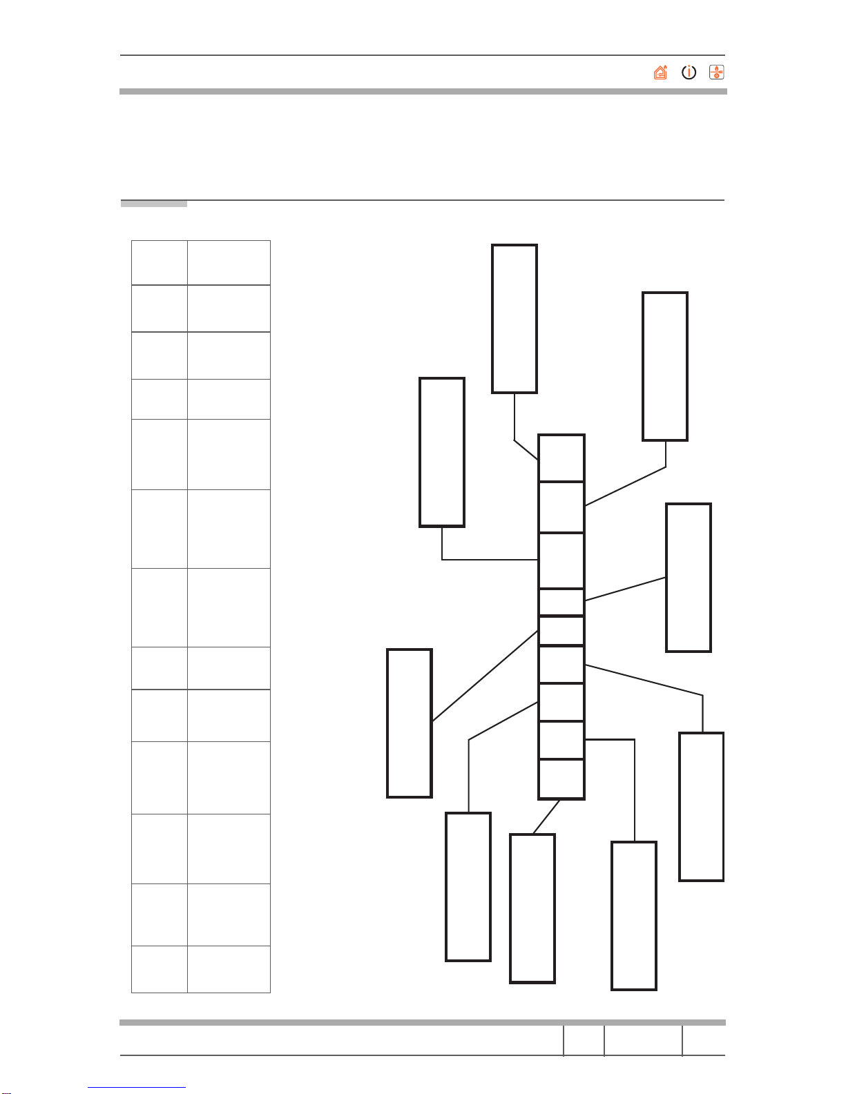
1 FEATURES OF THE APPLIANCES
L55 VE LCD L55 NF LCD
User interface
1 LCD Display: for adjusting the refrigerator and freezer compartments, setting the various
functions and signalling alarm conditions to the user.
1 FZ knob: for switching on the appliance and adjusting the freezer compartment.
1 FR knob: for adjusting the refrigerator compartment.
1 Mode button: for selecting functions.
1 Select button: for activating/deactivating selected functions and resetting the buzzer.
Loads
1 COMPRESSOR
1 SOLENOID VALVE
1 FR LAMP
1 AMBIENT FAN (in fridge comp.)
1 CONDENSER FAN (not run by boards)
1 COMPRESSOR
1 SOLENOID VALVE
1 FR LAMP
1 AMBIENT FAN (in fridge comp.)
2 DEFROST ELEMENTS (evap. and
drip tray)
1 NF FZ FAN (in freezer comp.)
1 CONDENSER FAN (not run by boards)
1 THERMOFUSE (not run by boards)
Input
2 KNOBS
2 BUTTONS
1 FR PROBE (in fridge comp.)
1 FR EV PROBE (in contact with FR
evaporator )
1 FZ AMBIENT PROBE (in freezer comp.)
1 FR DOOR SWITCH (two contact switch
on side of fridge comp.)
2 KNOBS
2 BUTTONS
1 FR AMBIENT PROBE (in fridge comp.)
1 FR EV PROBE (in contact with FR
evaporator )
1 FZ AMBIENT PROBE (in freezer comp.)
1 FZ EV PROBE (in freezer comp.)
1 FR DOOR SWTICH (two contact switch
on side of fridge comp.)
Output 1 LCD DISPLAY
1 BUZZER (on electronic board)
External serial line Output in the compressor bay
Eeprom memory On electronic board
Fridge thermostat Mode Freezer thermostatSelectLCD display
Merloni Elettrodomestici
55 CM WIDE BUILT-IN FRIDGE-FREEZERS
Technical Manual
I 04-10-22/01 4-33
Language Issue/Edition Page
2 LEGEND - RESTYLING FOR ARISTON BUILT-IN MODELS
L=55 CM
EUIA4216STB
Blank: = The characteristic is not specified in the description.
(*) Definitive names of the Ranges will be communicated as soon they have been approved.
CHANNEL STRUCTURE TYPE CONDENSERCO
OLING
CAPACITY
(LITRES)
Line
(Design) STAR RATING REFRIGERATION
TYPE
SPECIAL
PERFORMANCE
ENERGY
CLASS GAS DOOR
OPENING MARKET
B=Bult-in C=Combi
D=Double door
O=One Door
T=Under (Table)
F=Freezer
P=Decor panelable
A=Load-bearing
X=Cabinet
Blank=Built-in
S=Self Ventilated
Blank=Nothing
2 numbers 1=Style
2=Ecotech
3=Class
Blank=Combi
Blank=Double door
o+4=One Door
0+4=Under (Table)
Blank=Freezer
Blank=Static
V=Ventilated
N=No-Frost
G=Global Air
(No-Frost)
E=Electronic
D=Digital
A=Onlyfor
class A
Blank=R134
a I=R 600
Blank=Right
S=Left
EU=Europe
EX=Export
UK
etc.
Range = ECO
Eff Class. A
Europe
R 600
4 Star Rating
160 litres
Under (Table)
Built in
Self Ventilated
Merloni Elettrodomestici
55 CM WIDE BUILT-IN FRIDGE-FREEZERS
Technical Manual
I 04-10-22/01 5-33
Language Issue/Edition Page
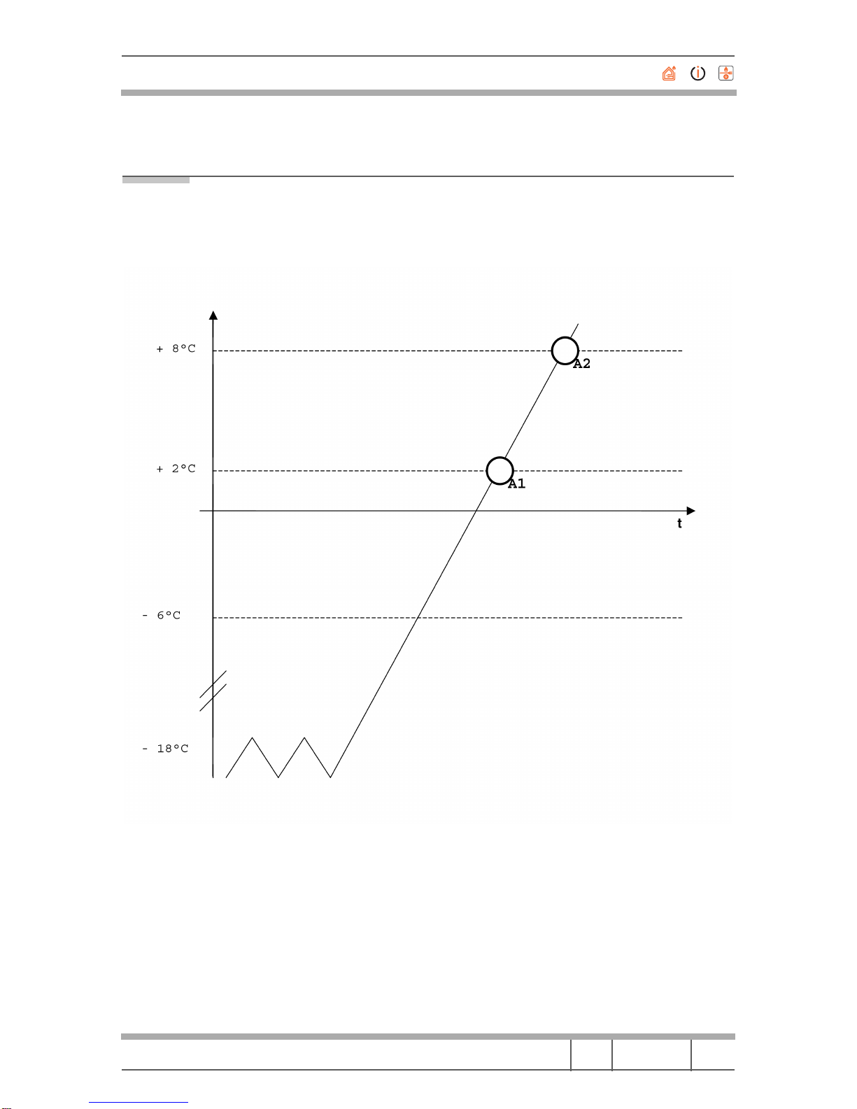
3 ALARM MESSAGES
Alarm messages, coded A1 and A2, refer exclusively to the Freezer compartment.
Their function is to alert the user to the storage condition of food.
An A1 alarm signal is triggered when:
• the freezer temperature is higher than +2 °C;
• the freezer temperature stops for more than 4 hours, between -6 °C and
+2 °C.
An A2 alarm signal is triggered when:
• the freezer temperature is higher than +8 °C;
• an A1 alarm signal has been ongoing for over 24 hours.
Merloni Elettrodomestici
55 CM WIDE BUILT-IN FRIDGE-FREEZERS
Technical Manual
I 04-10-22/01 6-33
Language Issue/Edition Page
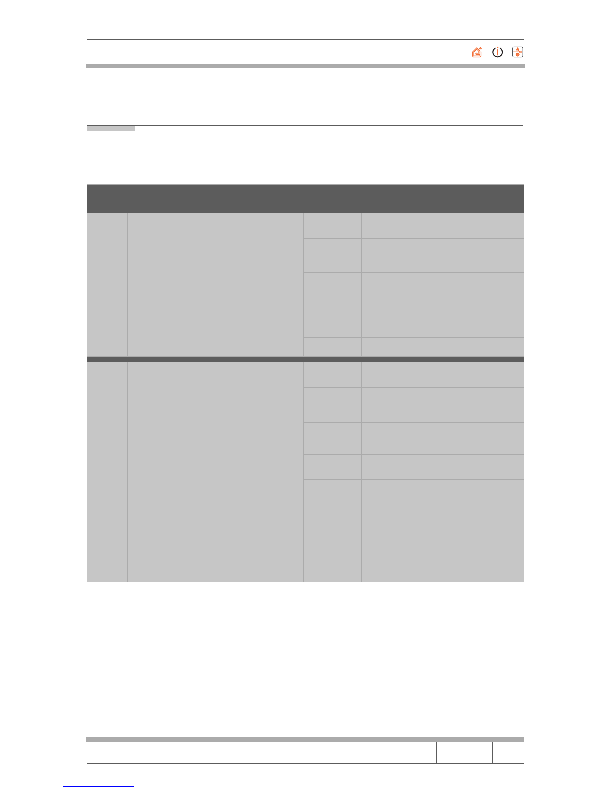
4 AUTOTEST
This helps with a quick check of the loads, which otherwise are difficult to acti-
vate, as well as of the probes and the EEPROM memory.
(*) Before using the Autotest it is advisable to check the correct operation of the refrigerator lamps and the
buzzer which are used for signalling possible malfunctions.
MODEL ACTIVATION (*) DEACTIVATION CHECK RESPONSE
Appliance OFF:
freezer knob to zero
4 min after activation Fridge lamp Visual check by operator (the fridge lamp
stays on approx. 15sec)
L55 VE
LCD
Press the SELECT
button for more than
3sec
When the appliance is
switched on again
Ambient fan Operator's visual check
Probes (active
after approx.
10sec)
• fridge ambient fan fault - Super Cool
function symbol starts flashing;
• freezer ambient fan fault - the Super
Freeze function symbol starts flashing;
• fridge evaporator probe fault - Holiday
function symbol starts flashing.
EEPROM Buzzer sounds if KO
Appliance OFF:
freezer knob to zero
4 min after activation Fridge lamp Visual check by operator (the fridge lamp
stays on approx. 15sec)
Press the SELECT
button for more than
3sec
When the appliance is
switched on again
Ambient fan Operator's visual check
L55 NF
LCD
Freezer fan Operator's visual check
Multiflow
resistor
Operator's visual check
Probes (active
after 10s) • fridge ambient fan fault - Super Cool
function symbol starts flashing;
• freezer ambient fan fault - the Super
Freeze function symbol starts flashing;
• fridge evaporator probe fault - Holiday
function symbol starts flashing.
• freezer evaporator probe fault - Ice
Party function symbol starts flashing.
EEPROM Buzzer sounds if KO

Merloni Elettrodomestici
55 CM WIDE BUILT-IN FRIDGE-FREEZERS
Technical Manual
I 04-10-22/01 7-33
Language Issue/Edition Page
5 ANALYSIS OF LOADS
1. Compressor
Information
How It Works: they are managed by the microcontroller based on the temperatures
measured by the probes.
Protection time: (about eight minutes) the compressor is forced not to switch itself on
before this period of time has elapsed from the last time it was switched off.
Black Out: the compressor starts running again immediately.
On/Off (on display): observes the compressor's 8 minute delayed start.
Possible cause of malfunction
Microcontroller management
Compressor driver circuit on the board
Connection on the board
Wiring
Connection on the compressor
Internal compressor breakdown/fault
TESTING:
General on the appliance: force the compressor to switch on by activating the
24h SUPER FREEZE function and check that the compressor switches on. Remember
the 8 minutes of compressor protection.
Wiring: check for continuity and short circuits; check the connections (connectors and
terminals); check for presence of voltage.
Component: check with simulated load (lamp); direct check of the compressor (pow-
ered directly).
Electronic board: visual check and quick check of the board (blowouts or burnouts,
etc.); check by using a replacement.

Merloni Elettrodomestici
55 CM WIDE BUILT-IN FRIDGE-FREEZERS
Technical Manual
I 04-10-22/01 8-33
Language Issue/Edition Page
2. Fridge Lamp and Fridge Door Switch
INFORMATION:
How It Works: the lamp can only be switched on with the appliance ON and the
fridge door open. After the fridge door has been open for 2 minutes the lamp starts
flashing and an acoustic alarm sounds. After 4 minutes the flashing becomes quicker.
POSSIBLE CAUSE OF MALFUNCTION:
Microcontroller management
Refrigerator door circuit input on the board
Lamp driver circuit on the board
Connection on the board
Wiring
Connections on the lamp
Connections on fridge door switch
Lamp
Fridge door switch
TESTING:
General on the appliance: switch on the appliance, open the door and verify that the
lamp switches on.
carry out the check using the Autotest procedure.
Wiring: check for continuity and short circuits; check the connections (connectors and
terminals); check for presence of voltage.
Component: visual check of the lamp; direct check of the lamp (powered directly);
check by using a replacement lamp. One possible cause of incorrect lamp functioning is
a problem with the fridge door switch.
Electronic board: visual check and quick check of the board (blowouts or burnouts,
etc.); check by using a replacement.

Merloni Elettrodomestici
55 CM WIDE BUILT-IN FRIDGE-FREEZERS
Technical Manual
I 04-10-22/01 9-33
Language Issue/Edition Page
3. Solenoid valve
INFORMATION:
Solenoid valve (EV) operation is linked to demand for refrigeration from the two com-
partments (FR and FZ).
The component is driven by a series of electrical impulses and, once forced into posi-
tion, is able to maintain that position without the need for any further energy. The elec-
trical impulses are simply supply voltage half-waves specially selected by the control
board: (by means of special circuitry on the board: triac) positive half-waves force the
component in one direction and negative half-waves force it the opposite way. The link
between the condition of the solenoid valve and the appliance's thermodynamic circuits
(FR or FZ) depends on the connection of the driver cable and the capillary coupling.
The control board sends first of all a sequence of 10 impulses to force the solenoid
valve into the opposite state to that which is necessary and, after a few seconds (2-3s),
sends another 10 impulses to force the solenoid valve into the desired state. The pur-
pose of this is to move the internal stop and thus ensure, during the exchange, the re-
moval of any impurities.
To ensure that no interference has altered the state of the solenoid valve (which is sen-
sitive to electrical interference) and that it is in the desired condition, it is automatically
refreshed every 15 minutes.
The fridge nonetheless always has priority over the freezer.
POSSIBLE CAUSE OF MALFUNCTION:
Microprocessor management
Solenoid valve driver circuit on the board
Connection on the board
Wiring
Connections on the solenoid valve
Solenoid valve
TESTING:
General on the appliance: direct cold air into the freezer compartment only by
switching on the appliance and turning the fridge knob to zero. Check that only the
freezer compartment is cold. Subsequently, turn the fridge knob to switch on both
compartments. Check that cold air is directed into the refrigerator compartment.
Wiring: check for continuity and short circuits; check the connections (connectors and
terminals); check for presence of voltage.
Component: check with simulated load (lamp); direct check of the solenoid valve.
Electronic board: visual check and quick check of the board (blowouts or burnouts,
etc.); check by using a replacement.

Merloni Elettrodomestici
55 CM WIDE BUILT-IN FRIDGE-FREEZERS
Technical Manual
I 04-10-22/01 10-33
Language Issue/Edition Page
Tirac not permitted
Tirac in conduction 3.3 ms
20 msec (50 Hz)
Driver signal EV
(10 impulses)
Mains supply signal
Merloni Elettrodomestici
55 CM WIDE BUILT-IN FRIDGE-FREEZERS
Technical Manual
I 04-10-22/01 11-33
Language Issue/Edition Page
4. Ambient fan
INFORMATION:
How It Works: when cold air is directed into the refrigerator compartment, the ambi-
ent fan is also activated. Operation of this fan is partialized (first on then off) in accord-
ance with the position of the fridge knob, taking into account in any case an initial delay.
After door opening, during the fridge compressor's subsequent On cycle, the ambient
fan will remain on until the compressor's next OFF cycle (therefore not partialized).
POSSIBLE CAUSE OF MALFUNCTION:
Microcontroller management
Fan driver circuit on the board
Connection on the board
Wiring
Connections on the fan
Ambient fan
TESTING:
General on the appliance: direct cold air into both fridge and freezer compartments,
open the door and hold down the fridge door switch. Visually check that, after the de-
layed activation period has elapsed, the ambient fan starts working.
Carry out the check using the Autotest procedure.
Wiring: check for continuity and short circuits; check the connections (connectors and
terminals); check for presence of voltage.
Component: check with simulated load (lamp); directly check the ambient fan (with
special wiring).
Electronic board: visual check and quick check of the board (blowouts or burnouts,
etc.); check by using a replacement.
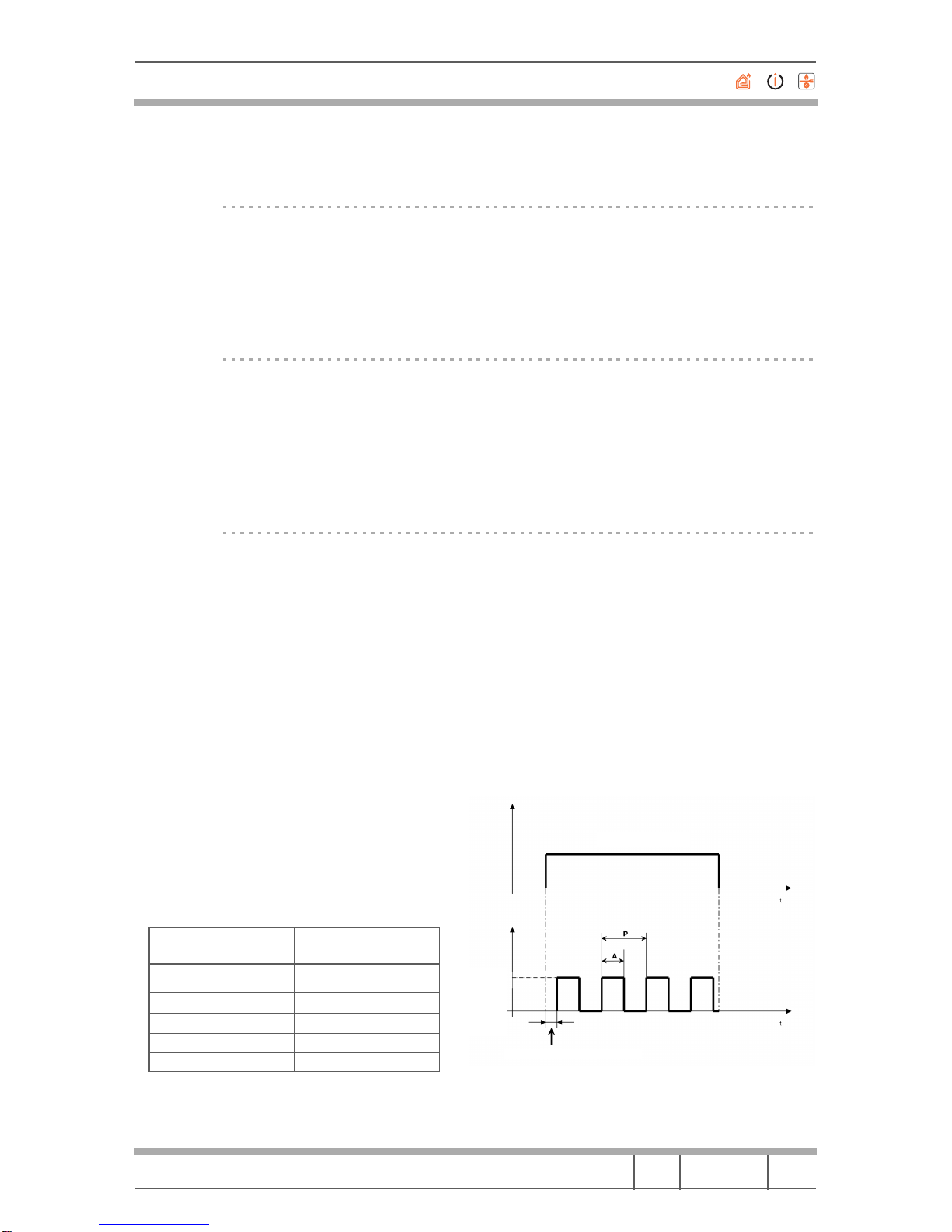
LEGEND
P = fixed period of 10 minutes
A = ambient fan ON time (variable)
E.g: time A in the figure is relative to the fridge
knob set to +4 °C.
Fridge knob position Time A
(% compared to P)
+8 °C 0%
+7 °C 0%
+6 °C 20%
+4 °C 50%
+2 °C 100%
fridge compressor ON
7 minute delay in activation of ambient fan
Fan
ON
Fan
OFF

Merloni Elettrodomestici
55 CM WIDE BUILT-IN FRIDGE-FREEZERS
Technical Manual
I 04-10-22/01 12-33
Language Issue/Edition Page
5. Defrost elements (No-Frost only)
INFORMATION:
How It Works: the two elements (evaporator 72 W and 650 Ohm and drip tray 15 W
and 3200 Ohm) are both activated solely during the defrosting phase, which is ended
based on temperature or time.
In any case, the power supply of the 72 W resistor is cut off if the probe measures a
temperature of approximately +8 °C.
The time lapse between one defrosting cycle and another varies between a maximum of
30 hours to a minimum of 6 hours, and is determined by the electronic board in accord-
ance with the table below, based on the time taken by the Freezer probe to reach +8 °C.
POSSIBLE CAUSE OF MALFUNCTION:
Microcontroller management
Resistor driver circuit on the board
Connection on the board
Wiring
Connection on the elements
Elements
Blown thermo fuse
TESTING:
General on the appliance: Carry out the check using the Autotest procedure.
Wiring: check for continuity and short circuits; check the connections (connectors and
terminals); check for presence of voltage. check that the thermo fuse is not open.
Component: check with simulated load (lamp); direct check of the elements (powered
directly).
Board: visual check and quick check of the board (blowouts or burnouts, etc.); check by
using a replacement.
Time to reach +8 °C Defrost cycle interval Warnings:
• When a fast freeze cycle is selected,
defrosting is carried out after
14 hours.
• In the event of a power failure, the
freezer is automatically defrosted
following the first compressor
cycle.
16 minutes 30 hours
16/20 minutes 27 hours
20/24 minutes 26 hours
24/28 minutes 23 hours
28/32 minutes 21 hours
32/36 minutes 17 hours
36/40 minutes 13 hours
40 minutes 6 hours

Merloni Elettrodomestici
55 CM WIDE BUILT-IN FRIDGE-FREEZERS
Technical Manual
I 04-10-22/01 13-33
Language Issue/Edition Page
6. FZ Evaporator Fan (No-Frost only)
INFORMATION:
How It Works: it is always switched off with the appliance OFF and can be switched
on when the appliance is in the ON condition only if the compressor is switched on.
Delay in switching on: the fan has a start time delay of about two minutes compared
with that of the compressor and is activated only after the evaporator has cooled to be-
low -18 °C in the first cycle after a defrosting.
POSSIBLE CAUSE OF MALFUNCTION:
Microcontroller management
FZ evaporator fan driver circuit on the board
Connection on the board
Wiring
Connection on the FZ evaporator fan
FZ evaporator fan
TESTING:
General on the appliance: Carry out the check using the Autotest procedure.
Wiring: check for continuity and short circuits; check the connections (connectors and
terminals); check for presence of voltage. check that the thermo fuse is not open.
Component: check with simulated load (lamp); direct check of the fan (powered directly).
Board: visual check and quick check of the board (blowouts or burnouts, etc.); check by
using a replacement.

Merloni Elettrodomestici
55 CM WIDE BUILT-IN FRIDGE-FREEZERS
Technical Manual
I 04-10-22/01 14-33
Language Issue/Edition Page
7. Condenser fan
INFORMATION:
How It Works: when the appliance is OFF the fan is always OFF and when the appli-
ance is ON, the fan will be ON only when the compressor is running; when the com-
pressor is switched off the fan is also switched off.
POSSIBLE CAUSE OF MALFUNCTION:
Microcontroller management (for the compressor)
Driver circuit (for the compressor) on the board
Connection on the compressor terminal board
Wiring
Connection on the condenser fan
Condenser fan
TESTING:
General on the appliance: force the compressor to switch on (and, as a result, the fan)
by activating the 24h SUPER FREEZE function and verify that the fan switches on at
the same time as the compressor. Remember the 8 minutes of compressor protection.
Wiring: check for continuity and short circuits; check the connections (connectors and
terminals); check for presence of voltage.
Component: check with simulated load (lamp); direct check of the fan (powered directly).
Board: the fan is not controlled directly by the electronic board, but indirectly through
the control of the compressor.

Merloni Elettrodomestici
55 CM WIDE BUILT-IN FRIDGE-FREEZERS
Technical Manual
I 04-10-22/01 15-33
Language Issue/Edition Page
8. Thermo fuse (No-Frost only)
INFORMATION:
How It Works: it is a safety device which is tripped, cutting off the electrical power
supply to the 72 W and 15 W resistors, when the temperature of the freezer evaporator
reaches approximately +85 °C.
The thermo fuse is housed on the metal support in contact with the freezer evaporator.
This component, having been tripped due to excessive temperature, can no longer be
used.
POSSIBLE CAUSE OF MALFUNCTION:
Connection on thermo fuse
Wiring
Thermo fuse
TESTING:
General on the appliance: carry out the check using the Autotest procedure and
check for correct functioning of the defrosting resistors (a malfunction could in any
case be due not only to the thermo fuse: see paragraphs relating to the two loads).
Wiring and component: check for continuity and short circuits; check the connec-
tions (connectors and terminals).

Merloni Elettrodomestici
55 CM WIDE BUILT-IN FRIDGE-FREEZERS
Technical Manual
I 04-10-22/01 16-33
Language Issue/Edition Page
6 ANALYSIS OF PROBES
INFORMATION:
How It Works: these are temperature sensors which associate measurements in de-
grees centigrade with resistive values that are easily read and managed by the micro-
processor on the board.
In particular, as the temperature increases, electrical resistance decreases, and as the
temperature decreases, resistance increases.
The control system utilizes four probes, which have the following functions:
FREEZER AMBIENT PROBE
This probe is located in the freezer compartment; its task is to measure the temperature
and communicate it to the microprocessor, which uses this data to manage the alarms
and the fast freezing function.
FRIDGE AMBIENT PROBE
This probe is located on the right hand wall inside the fridge compartment, inside a small
plastic cage. Its task is to measure the internal fridge temperature and communicate it to
the microprocessor, which uses this data to regulate the refrigerator's thermostat.
This is therefore the most important probe in terms of refrigerator operation, since it
determines the thermal cycles (activating and deactivating the compressor and solenoid
valve).
REFRIGERATOR EVAPORATOR PROBE
This probe is located on the fridge evaporator in the same area as the thermostat bulb
in the electromechanical version. Its task is to measure the temperature at the end of
the defrosting cycle (approx. +5 °C) and communicate it to the microprocessor every
time a defrost cycle is carried out.
FREEZER EVAPORATOR PROBE (No-Frost only)
This probe is located in contact with the freezer evaporator. Its task is to measure the
temperature (+8 °C) during freezer defrosting and deactivate the two resistors, thus
ending the defrost cycle.
If the FZ AMBIENT probe breaks: the appliance continues working since it has an al-
ternative timed mode, but obviously the temperature alarms will no longer be signalled!
If the FR AMBIENT probe breaks (only on models with display on the door): the ap-
pliance continues working since the smart microprocessor handles alternation between
fridge and freezer.
The Autotest procedure can in any case be used to pinpoint which probe is not working!

Merloni Elettrodomestici
55 CM WIDE BUILT-IN FRIDGE-FREEZERS
Technical Manual
I 04-10-22/01 17-33
Language Issue/Edition Page
POSSIBLE CAUSE OF MALFUNCTION:
Microprocessor management
Monitoring circuit on the board
Connection on the board
Wiring
Probes
TESTING:
General on the appliance: Carry out the check using the Autotest procedure.
Wiring and component: check for continuity and short circuits; check the connec-
tions (connectors and terminals); check that the resistive values correspond to the val-
ues given by the manufacturer (heat the probe touching it with your hand where possi-
ble and check the variation in the resistive value).
Board: visual check and quick check of the board (blowouts or burnouts, etc.); check by
using a replacement.
Temp °C Ohm
Resistor Temp °C Ohm R
esistor Temp °C Ohm
Resistor
50 973.6 -2 9701 -22 29045
45 1181 -3 10215 -23 30797
40 1493 -4 10759 -24 32668
35 1765 -5 11337 -25 34666
30 2176 -6 11949 -26 36800
25 1700 -7 12598 -27 39082
20 3360 -8 13288 -28 41521
15 4225 -9 14019 -29 44131
10 5348 -10 14795 -30 46921
9 5611 -11 15620 -31 49910
8 5888 -12 16497 -32 53111
7 6182 -13 17429 -33 56541
6 6491 -14 18420 -34 60218
5 6818 -15 19475 -35 64161
4 7164 -16 20596 -36 68393
3 7529 -17 21791 -37 72932
2 7916 -18 23063 -38 77808
1 8325 -19 24418 -39 83046
0 8758 -20 25862 -40 88577
-1 9216 -21 27402
Merloni Elettrodomestici
55 CM WIDE BUILT-IN FRIDGE-FREEZERS
Technical Manual
I 04-10-22/01 18-33
Language Issue/Edition Page
7 ANALYSIS OF MEMORY
INFORMATION:
How It Works: is necessary to maintain all the appliance's operating parameters; com-
munication between the micro and the memory (on a special 8 pin socket on the Power
board) can have a strong bearing on the functioning of the appliance and on the user's
adjustments.
POSSIBLE CAUSE OF MALFUNCTION:
Microcontroller management
Memory circuit on the board
Memory
TESTING:
General on the appliance: Carry out the check using the Autotest procedure.
Board: visual check and quick check of the board (blowouts or burnouts, etc.); check by
using a replacement.

Merloni Elettrodomestici
55 CM WIDE BUILT-IN FRIDGE-FREEZERS
Technical Manual
I 04-10-22/01 19-33
Language Issue/Edition Page
8 ANALYSIS OF BUZZER
INFORMATION:
How It Works: the operation of buzzer is closely connected to the signalling and alarm
functions: the buzzer is soldered onto the Power board in the control box on the instru-
ment panel.
POSSIBLE CAUSE OF MALFUNCTION:
Microcontroller management
Driver circuit on the board
Buzzer
TESTING:
General on the appliance and component: starting from the appliance ON condi-
tion, keep the refrigerator and/or the freezer door open for more than three to four
minutes so as to force the door open alarm condition; check that the buzzer starts to
sound and turns off just by the door being closed (failure to activate could also be due
to the switches malfunctioning: see relative paragraph).
Board: visual check and quick check of the board (blowouts or burnouts, etc.); check by
using a replacement.

Merloni Elettrodomestici
55 CM WIDE BUILT-IN FRIDGE-FREEZERS
Technical Manual
I 04-10-22/01 20-33
Language Issue/Edition Page
9 ANALYSIS OF LCD DISPLAY
INFORMATION:
How It Works: the user interface includes an LCD display for visualization of settings
and for displaying possible malfunctions in the freezer compartment.
POSSIBLE CAUSE OF MALFUNCTION:
Microprocessor management
Driver circuit on the board
Display
TESTING:
General on the appliance and component: switch on the appliance and turn the two
knobs and press the buttons to change the settings.
Wiring: (between the two boards) check for continuity and short circuits; check the
connections (connectors and terminals).
Board: visual check and quick check of the Display board (blowouts or burnouts, etc.)
check by using a replacement. It is recommended to also check the Power board.
This manual suits for next models
1
Table of contents


