Merriott EMMETI ClimaAir CA VS 7-2P User manual

ClimaAir
Installation, operating
& instruction manual
Fan Convector
PLEASE LEAVE THIS MANUAL WITH THE END USER

Product Information
. Safety and General Information
. Safety Information
. General Information
. Technical Data
. Dimensions
. Installation
. Positioning the Unit
. Installation Clearances
. Side Opening
. Vertical Floor or Wall Installation
. Horizontal Ceiling Installation (VS, VSI)
. Mounting Front Grille Safety Support (CA VS)
. Air Intake Grille Fixing
. Water Connections
. Condensate Discharge
. Filling and Venting the System
. Electrical Connections
. Maintenance
. Cleaning the Outer Casing
. Cleaning the Air Filter
. Faults and Troubleshooting
. Troubleshooting
. Fault-Finding Guide
. Instructions -Way Valve
. Warnings
. -Way Valve Parts List
. Return Valve Pre-Setting Screw Adjustment
. Valve Insulation
. Control Panel Connection and Configuration
. Connection and Configuration of Control Panel
. Cooling Mode Additional Functionality
. Night-Time Heating Additional Functionality
. -Pipe & -Pipe Models with
Integrated Control
. -Pipe & -Pipe Models with
Wall-Mounted Remote Control
. Connection of Multiple Units Using
Wall-Mounted Remote Control
. LED Indications (A) -Pipe & -Pipe Models
with Wall-Mounted Remote Control
. Remote Control Panel Mounting
. Wiring Connection to Remote Control
. Presence Detection Sensor Input Connection
– Remote Control Units
. Integrated and Remote Control Setup Menu
. Setup Menu
. -V Models
. -V Fan Control
. Connection Diagram with -V DC
Thermostats/Signals
. Fan Speed Regulation
. User Instructions
. Integrated and Remote Control Operation
. Display
. Key Function
. Activation
. Heating/Cooling Mode Settings
. Stand-By
. Temperature Selection
. Automatic Operation
. Silent Operation
. Night-Time Operation
. Operation at Maximum Fan Speed
. Key Lock
. Reduce Brightness to Minimum
. Room Temperature Probe Regulation Offset
. Switching Off for Longer Periods
Contents
3
Product Information
We want to thank you for choosing one of our products. We are confident that you will be happy with your selection because
it represents the state of the art in the technology of climate control.
ClimaAir Fan Convectors are available with casing or without casing, in different lengths.
CA VS - Surface Mounted Models can be mounted vertically on the wall or horizontally on the ceiling, with the option for integrated
controls (not ceiling), remote control or V option with BMS input or V remote control input. All units are available in or -pipe
options, and all units are supplied with pre-fitted valves.
CA VSI - Recessed Models can be mounted vertically (recessed wall mounting) or horizontally (recessed ceiling mounted), with the option
for remote control or V option with BMS input or V remote control input.
Conformity
This unit complies with European directives:
>Low voltage directive //EU
>Electro-magnetic compatibility //EU
>RoHS Directive //EU
This unit complies with UK directives:
>Electrical Equipment (Safety) Regulations
>Electromagnetic Compatibility Regulations
>RoHS Regulations
Symbols
The following symbols provide the necessary guidance for correct, safe use of this product.
Hot Surface
Signals that the parts of the product could be hot
and should not be touched without great care.
Protective Earth
Identifies any terminal intended for connection
to an external conductor for protection against
electric shock in case of a fault, or the terminal of
a protective earth electrode.
Refer To Manual
Refer to relevant instructions within the
product manual.
Warning / Caution
Signals that an appropriate safety instruction
should be followed or caution to a potential hazard.
Dangerous Voltages
Indicates hazards arising from dangerous voltages.
Heavy
Indicates that this product is heavy, and provision
should be made for safe lifting and handling.
Safety Pictograms
These symbols may appear in the manual or on the product:
ClimaAir
ClimaAir4
Safety and General Information
.
. Safety Information
This appliance MUST NOT be
installed in a bathroom or other
similar high humidity areas.
This appliance MUST be earthed.
This appliance must be installed
by a qualified engineer.
The electrical installation must
comply with local or national
wiring regulations and should
be carried out by a qualified
electrician.
This appliance can be used by
children aged from 8 years and
above and persons with reduced
physical, sensory or mental
capabilities or lack of experience
and knowledge if they have been
given supervision or instruction
concerning use of the appliance
in a safe way and understand the
hazards involved. Children shall
not play with the appliance.
Cleaning and user maintenance
shall not be made by children
without supervision.
For the correct installation of this
product, it is essential that fixing
is carried out in such a way that
it is suitable for intended use and
predictable misuse. A number of
elements need to be taken into
consideration including the fixing
method used to secure it to the
wall, the type and condition of
the wall itself, and any additional
potential forces or weights that
may happen to be applied to the
unit, prior to finalising installation.
This product must not be installed
immediately below a socket outlet.
This product must not be installed in
areas where excessive dust exists.
This product can be hot when in
use, and as such, presents a risk
of burns to users on prolonged
contact. The temperature of the
product is dependent on system
water temperature, as set by the
installer or end user. Installers
and users should ensure that
those who may come into close
proximity to the product are
aware of the risk of burns.
The recessed ClimaAir model
does not have a grille or covering
plate. The installer must provide
safety guards and air inlet/outlet
grills to prevent accidental
contact with the device.
DO NOT cover or obstruct the air
inlet or outlet grilles.
Isolate electrical supply before
carrying out any cleaning or
maintenance activities.
This instruction leaflet is an
integral part of the appliance.
The installer MUST ensure it is
left with the end user.
All repair and maintenance
activities must be performed by
suitably qualified personnel.

ClimaAir 5
. General Information
Before proceeding with the installation, unpack the product and
make sure that all the components are present, and that there is
no concealed shipping damage.
Components include:
>Unit
>Instruction manual
>Template
>Accessories/mounting kit
This appliance has been designed both for heating and/or
cooling applications and must be installed for this use only.
The installation must take into consideration stated
performance characteristics.
Check the location where the product is to be installed, the
wall surface must be flat and the specified product clearances
available. If fitted to a stud wall, there may be an adverse effect
on sound levels especially at higher fan speeds. If the product is to
be used for cooling applications, the disposal of condensate must
be considered.
If the appliance is not used for a long period of time,
it is recommended that the product is electrically isolated,
and the connecting valves are closed. Frost prevention
measures must be taken including use of anti-freeze
if appropiate.
Avoid prolonged physical contact with the direct air flow.
Do not leave the room closed for long periods. Periodically open
the windows to ensure fresh air exchange.
In the event of a water leak, isolate the electrical supply and
close connecting valves. Contact the installer or suitable
service engineer.
The manufacturer accepts no responsibility, either contractual
or for consequential loss, for any damage caused to persons,
animals of property as a result of incorrect installation, alteration,
maintenance or improper use.
To ensure that the installation is carried out correctly and that the
unit will perform as designed, carefully follow the instructions in
this manual. Failure to follow the instructions can not only cause
malfunctions of the appliance but will also invalidate the warranty
and hence Purmo Group shall not respond for any damage to
persons, animals or property.
. Technical Data
-Pipe Models
Technical Data (DC) Model VS CA VS -P CA VS -P CA VS -P CA VS -P CA VS -P
Model VSI CA VSI -P CA VSI -P CA VSI -P CA VSI -P CA VSI -P
Length VS mm
Length VSI mm
Heat exchanger water content VS/VSI L. . . . .
Maximum working pressure bar
Maximum inlet water temperature °C
Minimum inlet water temperature °C
Water connections Eurocone /" Eurocone /" Eurocone /" Eurocone /" Eurocone /"
Power supply V/ph/Hz // // // // //
Maximum power W
Weight VS kg
Weight VSI kg
-Pipe Models
Technical Data (DC) Model VS CA VS -P CA VS -P CA VS -P CA VS -P CA VS -P
Model VSI CA VSI -P CA VSI -P CA VSI -P CA VSI -P CA VSI -P
Length VS mm
Length VSI mm
Cooling coil water content L. . . . .
Heating coil water content L. . . . .
Maximum working pressure bar
Maximum inlet water temperature °C
Minimum inlet water temperature °C
Water connections Eurocone /" Eurocone /" Eurocone /" Eurocone /" Eurocone /"
Power supply V/ph/Hz // // // // //
Maximum power W
Weight VS kg
Weight VSI kg
ClimaAir6
Safety and General Information (cont...)
.
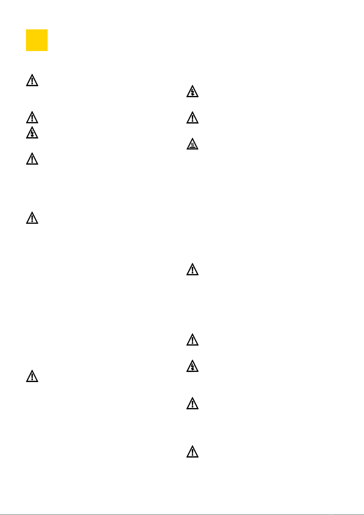
. Dimensions
FRONT VIEW SIDE VIEW
CA VSI -Pipe Models
Note: Optional feet are mm
Note: -pipe recessed unit shown without factory-fitted valves (included).
HEATING CIRCUIT IN COOLING CIRCUIT IN
HEATING CIRCUIT OUT COOLING CIRCUIT OUT
FRONT VIEW SIDE VIEW
CA VS -Pipe Models
Dimensions Model CA VS -P CA VS -P CA VS -P CA VS -P CA VS -P
Amm
a mm
a mm
37.5
80
131
579
449
206
102
83
G3/4"EK
G3/4"EK
A
a1
a2
∅ 14
126
A
73.573.5
18.5
468.5
228
G3/4“EK
180.5
14 99.5
G3/4“EK
194.5 316 65.5
576
14
468.5
228
79.5
37.5
∅ 14
83.2
116
83.5
126
A
73.573.5
18.5
468.5
228
G3/4“EK
180.5
14 99.5
G3/4“EK
194.5 316 65.5
576
14
468.5
228
79.5
37.5
∅ 14
83.2
116
83.5
37.5
80
131
579
449
206
102
83
G3/4"EK
G3/4"EK
A
a1
a2
∅ 14
Dimensions Model CA VSI -P CA VSI -P CA VSI -P CA VSI -P CA VSI -P
Amm
ClimaAir 7
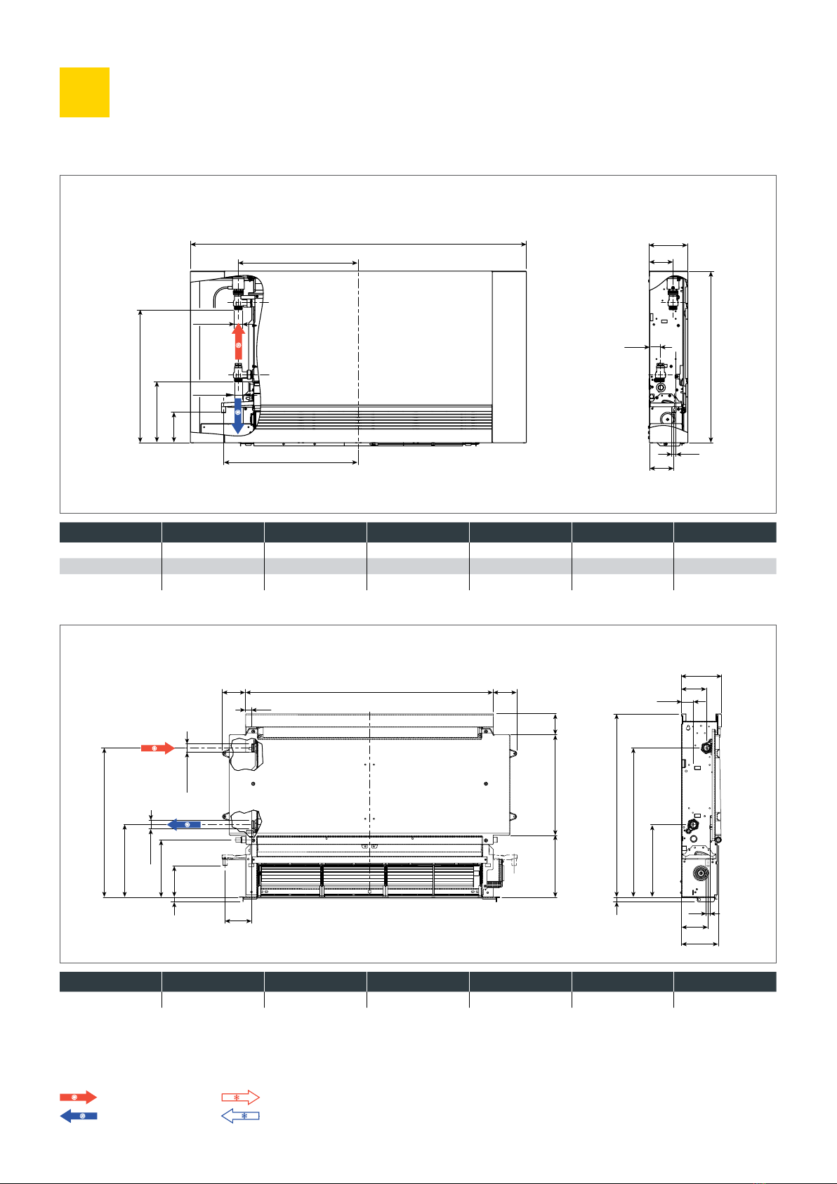
FRONT VIEW SIDE VIEW
CA VSI -Pipe Models
Note: Optional feet are mm
Note: -pipe recessed unit shown without factory-fitted valves (included).
HEATING CIRCUIT IN COOLING CIRCUIT IN
HEATING CIRCUIT OUT COOLING CIRCUIT OUT
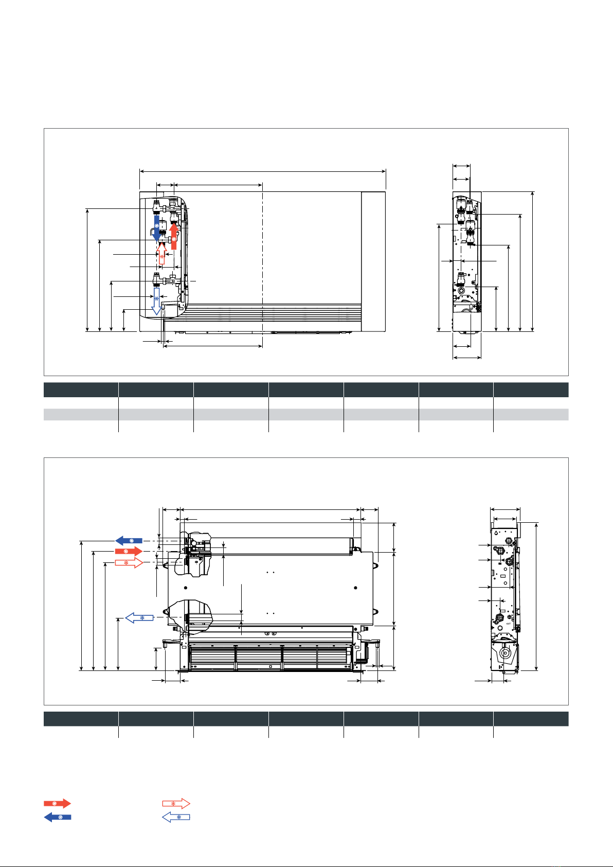
FRONT VIEW SIDE VIEW
CA VS -Pipe Models
Dimensions Model CA VS -P CA VS -P CA VS -P CA VS -P CA VS -P
Amm
a mm
a mm
Dimensions Model CA VSI -P CA VSI -P CA VSI -P CA VSI -P CA VSI -P
Amm
80
131
639
83
G3/4"EK
102
230
206
394
536
491
37.5
76
418
560
79
54
∅14
G3/4"EK
a2
A
a1
80
131
639
83
G3/4"EK
102
230
206
394
536
491
37.5
76
418
560
79
54
∅14
G3/4"EK
a2
A
a1
126
636
228
468
98.5
515
558
73.5
65 72
55.5
A
30
73.5
30
125.6316194.4
∅ 14
37
80
41
76
99.5 G3/4“EK G3/4“EK
G3/4“EK
G3/4“EK
126
636
228
468
98.5
515
558
73.5
65 72
55.5
A
30
73.5
30
125.6316194.4
∅ 14
37
80
41
76
99.5 G3/4“EK G3/4“EK
G3/4“EK
G3/4“EK
ClimaAir8
Installation
.
. Positioning the Unit
This unit must not be installed in a bathroom, in damp
areas or places with possible contact with water.
Avoid installing the unit:
> In positions subject to exposure to direct sunlight.
> In proximity to sources of heat.
> In places with oil fumes.
> In places subject to high frequency radio waves.
The following instructions refer to units with standard water
connections on the left hand side.
Make sure that:
> The wall on which the unit is to be installed is strong
enough to support the weight.
> The installation does not interfere with existing pipes
or electric wires.
> The wall is perfectly flat.
> That the air inlet and outlet are free of obstructions.
> The installation wall is preferably an external wall to
allow the discharge of the condensate outside.
> In case of ceiling installation the airflow is not directed
towards room occupants.
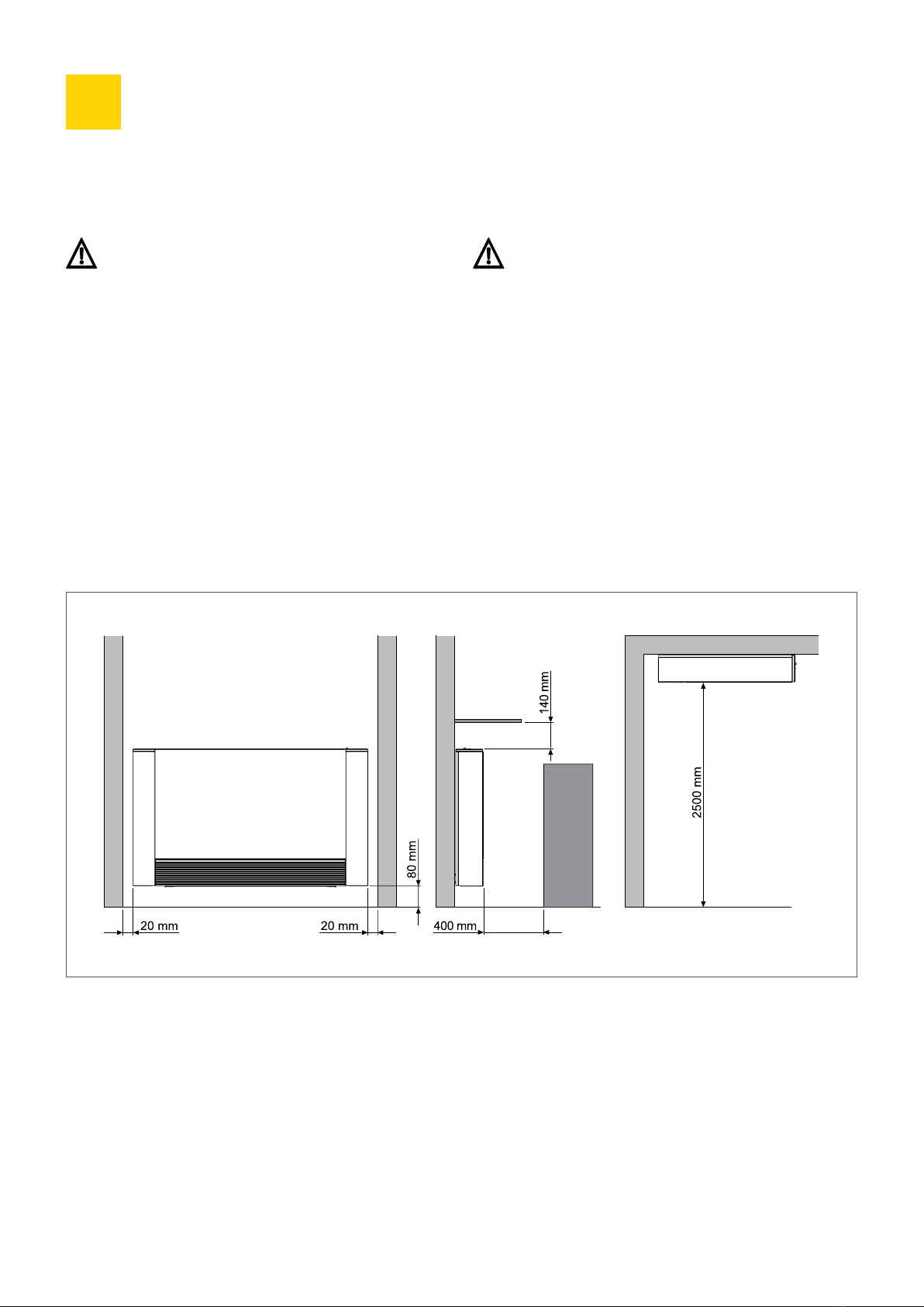
. Installation Clearances
The figure below indicates the minimum clearance between the CA VS Surface Mounted unit and any adjacent furniture.

ClimaAir 9
. Side Opening
>On the left-hand side, lift the cover that protects the screw,
loosen the screw that fixes the left panel, then move it slightly
to the left and lift it up.
>On the opposite side, lift the cover that protects the screw
and unscrew it.
>Move the side panel slightly to the right and lift it out.
. Vertical Floor or Wall Installation
When mounting on the floor with support feet, refer to the
product instructions supplied, and the instructions supplied
with the support feet.
Use the paper template provided to trace the position of the
bracket fixing holes on the wall. Drill the holes, insert the wall
plugs or other suitable fixing and secure the brackets.
Do not over-tighten the screws, check alignment with a spirit
level and make final adjustment. Mark the lower fixing points,
remove unit, then drill and plug wall. Fully tightening the bracket
screws, refit unit, check alignment and stability then secure using
bottom screw fixings.
AWall Plugs
BBrackets
B
AD
A
B
C
NOTE: Take care to ensure correct orientation of the wall brackets.
These should be fixed with small tabs pointing towards the fixing surface.
A AB
B
ACover
BFixing screws
CLeft panel
DRight panel
ClimaAir10
Installation (cont...)
.
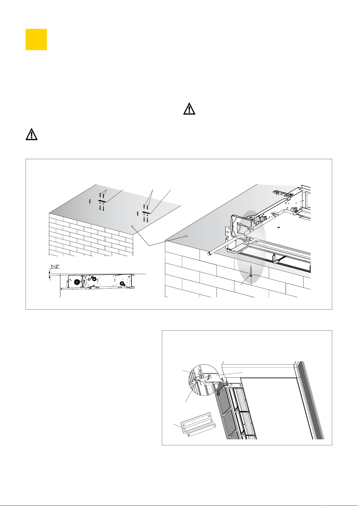
. Horizontal Ceiling Installation (VS, VSI)
Using the paper template provided, trace on the ceiling the
position of the two fixing brackets and the two rear screws.
Using a suitable drill, make the holes and insert the wall plugs
( for each bracket). Fix the two brackets. Do not over-tighten
the screws. Position the unit on the two brackets, keeping it in
position and then fix the two screws into the rear toggle bolts,
one on each side.
Make sure that there is sufficient inclination of the unit
towards the drainage pipe to facilitate the water drainage.
Additional washers or spacers may be needed.
Fully tighten all fixing screws.
For installation of the CA VS versions, horizontal condensation
collection tray accessory kits are available.
Carefully check the inclination of the condensate pipe.
Any backflow can cause water leakage.
AWall Plugs
BBrackets
CScrews
DDrainage Pipe
ceiling
A A
B
B
C
D
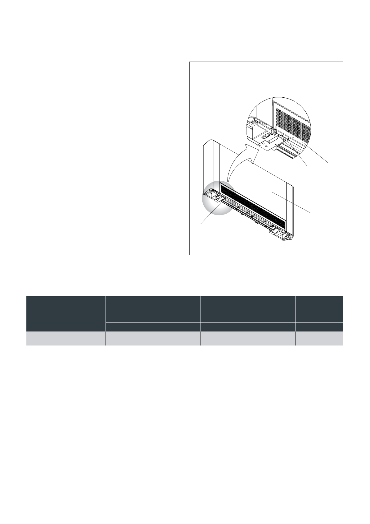
. Mounting Front Grille
Safety Support (CA VS)
When the unit is installed horizontally the inlet grille
must be attached to the chassis using the two tie straps
supplied in the accessory bag. This prevents the grille
from falling and ensures safe filter replacement.
Separate the two tie straps then;
>Remove the front grille and completely unscrew the
spring-loaded fixing screws.
>Fix one end of each tie to the chassis using the
spring-loaded fixing screws.
>Fix the other end of each tie to the grille using the
supplied screws.
>Refit the grille.
ATies
BSpring-loaded screws
CScrew fixing
A
A
B
C
ClimaAir 11
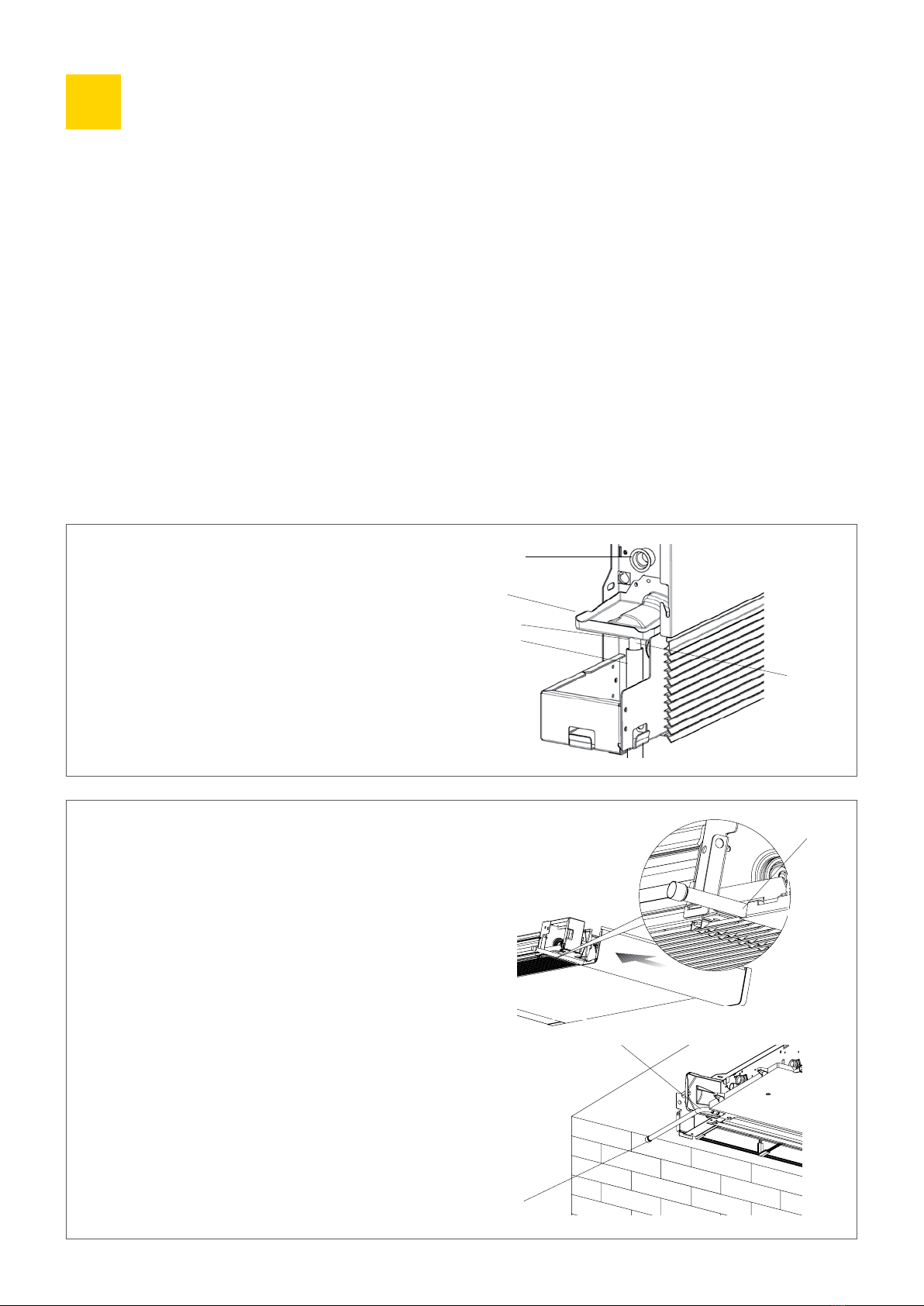
. Air Intake Grille Fixing
If the inlet grille is accidentally removed or left loose the fan will
stop and the grille safety alarm will activate. To prevent this from
happening the grille can be secured using the screws provided
(type TC . x .mm).
Fit the grille and secure by fitting the fixing screws into the
dedicated holes located on the grille's fixing bars as shown right.
The system should be designed and installed following best
practice by a qualified installer. The choice and sizing of the
pipework should take into account the number and size of the
units installed, and the performance characteristics of each unit.
Undersized pipes can cause malfunction of the units.
A suitable thread sealant should be used. The use of Teflon thread
sealant is advised when there is anti-freeze in the hydraulic circuit.
The water connection pipes and joints must be thermally insulated.
Partially insulating the pipes should be avoided and the insulation
should not be over-tightened.
After making the water connections check for leaks and cover
the connections with insulating material.
AInsert grille tab into lower bracket slot
BFixing screws
CCorrect position of grille tab
AB
C
Front View
. Water Connections
Minimum Pipeline Diameters
Model
CA VS -P CA VS -P CA VS -P CA VS -P CA VS -P
CA VSI -P CA VSI -P CA VSI -P CA VSI -P CA VSI -P
CA VS -P CA VS -P CA VS -P CA VS -P CA VS -P
CA VSI -P CA VSI -P CA VSI -P CA VSI -P CA VSI -P
Minimum
Pipeline diameters mm
ClimaAir12
Installation (cont...)
.
. Condensate Discharge
The condensate discharge pipes must be suitably sized (minimum
inside pipe diameter mm) and the pipeline positioned so that
it keeps a constant inclination, never less than . In a vertical
installation, the discharge pipe is connected directly to the
discharge tray, positioned underneath the water connections.
In a horizontal installation the discharge tube is connected to
the one already present in the unit.
For installation of the CA VS versions in a horizontal position,
horizontal condensation collection tray accessory kits
are available.
>If possible, the condensate pipework should be directed into
a rainwater discharge.
>When discharging directly into the main drains, it is essential
to make a syphon to prevent bad odours coming up the pipe
into the room. The curve of the syphon must be lower than the
condensation collection bowl.
>If the condensate needs to be discharged into a container, the
container must be open to the atmosphere and the tube must
not be immersed in water so that the normal outflow is
not restricted.
>If there is a height difference that could interfere with the
outflow of condensate, a pump must be fitted.
>In a vertical installation mount the pump under the lateral
drainage tray.
>In a horizontal installation the pump position must be decided
according to the specific requirements.
Such pumps are readily available.
On completion of the installation, it is advisable to check the
correct outflow of the condensate by slowly pouring about .l
of water into the collection tray in about minutes.
B
A
Condensate Discharge Pipe Connection
– Horizontally Mounted Units
To mount the horizontal condensate tray on the CAVS units
refer to the instructions supplied with accessory kits.
>Check that the "L" pipe (A) and the flexible rubber hose are
correctly connected to the condensate tray.
>Slide in the side of the unit keeping the pipe in position up
against the front grille.
>Fully close the side checking that the pipe remains tight in
the special groove on the side.
N.B. For a horizontal installation carefully note the
following precautions:
>Make sure that the unit is installed perfectly level or with
a slight inclination towards the condensate discharge point.
>Carefully insulate the flow and return pipes to the unit to
prevent any drops of condensate falling outside the drip tray.
>Insulate the condensate discharge pipe (B) along its
complete length.
Condensate Discharge Pipe Connection
- Vertically Mounted Units
Check that the condensate collection tray is present and
is correctly installed. Connect the discharge pipe (B) to
condensate collection tray (A).
ADischarge fitting
BCondensate pipework
CInternal charge point
DCondensate collection tray
B
A
C
D
Ømm
Ømm
ClimaAir 13
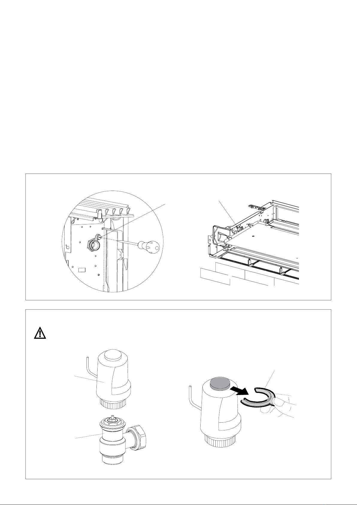
. Filling and Venting the System
When starting up the system, make sure that the return valve is
open. Refer to section . for correct setting. If there is no electric
power and the actuator valve has not already been powered up,
use the special tool, press the valve actuator and use the tool to
keep it open.
>Open all the shut off valves (manual or automatic).
>Start to slowly fill the system.
>For units installed in a vertical position, open the highest vent
of the heat exchanger; for appliances installed in a horizontal
position, open the highest positioned vent; for the -pipe
versions open the highest vents on both heat exchangers.
Vents can be opened using a screwdriver.
>When water starts coming out of the air vents, close them
and continue filling the system until reaching the nominal
system pressure.
>Check for leaks.
It is advisable to repeat these operations after the appliance
has been running for a few hours and to periodically check the
system pressure.
AThermostatic head
BValve
CRed plastic clip
WARNING: Commissioning Instructions – Opening the Thermostatic Valve
Remove the 'red plastic' clip from the thermostatic head before starting the system.
AVenting of the heat exchange
AA
C
A
B

ClimaAir14
Installation (cont...)
.
. Maintenance
Routine maintenance is essential to keep this product in a safe
and reliable working condition. End user maintenance activities
should be limited to cleaning of the outer casing and cleaning
of the air filter at appropriate intervals. Any other repair or
maintenance activity should be carried out by a qualified installer.
. Cleaning the Air Filter
To maintain air flow levels through the unit, air filters should be
cleaned at regular intervals. The frequency of cleaning should
take into consideration the concentration of impurities in the
local environment and duration of operation. Filter cleaning should
also be considered after a period of inactivity.
. Electrical Connections
Electrical connection must be made by a qualified
electrician in accordance with local and national
wiring regulations.
The unit must be connected to the mains supply using
a switched fused spur having mm separation on all poles.
This appliance must be earthed.
>Switch off electrical supply before making electrical connections.
>Remove control box cover.
>Make electrical connections to pcb.
>Secure power supply cables using strain relief clamps attached
to the control box.
>Refit control box cover.
. Cleaning the Outer Casing
Disconnect electrical supply before carrying out any
cleaning or maintenance activities.
Do not use abrasive cloths or abrasive or corrosive
detergents to avoid damaging the painted surfaces.
Wait until the parts have cooled down to avoid the risk
of burns. When necessary, clean the outer surfaces
of the ClimaAir with a soft damp cloth.
Removing the Filter
>Remove the front grille by lifting it slightly
and turn it until it comes completely out of
its seat.
>Remove the filter by pulling horizontally
outwards.
ALift front grille
BRotate grille forward
CFilter exposed
DRemove filter
AB
CD

ClimaAir 15
Cleaning the Filter
>Remove any dust with a vacuum cleaner.
>Wash the filter with clean running water. Do not use
detergents or solvents.
>Leave to dry.
>Re-fit the filter taking care to insert the lower back
edge into its seat.
Never use the unit without filters.
The appliance is fitted with a safety switch that
prevents operation of the fan with the front grille
missing or out of position.
After refitting the filter, check that the grille is
correctly mounted.
Energy Saving Tips
>Always keep the filters clean and as far as possible keep
the doors and windows closed in the room being conditioned
when the unit is in use.
>Limit where possible the effect of direct sun rays in the
rooms being conditioned (use curtains, shutters etc.).
>To refit the grille, insert the two lugs into the lower slots,
rotate it and attach to the upper chassis slots.
AFilter
BLower edge
CFilter locating channel
ATabs
BSlots
ABBC
A
B

ClimaAir16
Faults and Troubleshooting
.
. Troubleshooting
In the event of a water leak or malfunction immediately
cut off the power supply and close the system valves to
the unit.
Should one of the following faults occur, contact a qualified
service engineer. DO NOT intervene personally.
>The fan does not activate even if there is hot or cold water in
the hydraulic circuit.
>The appliance leaks water during the heating function.
>The appliance leaks water only during the cooling function.
>The appliance makes an excessive noise.
>Condensate forms on the front panel.
. Fault-Finding Guide
These operations must be carried out by a qualified installer or by a specialised service centre.
Effect Cause Solution
A delayed fan start up following set
temperature change or change of function.
The unit valves need time to open and as a
result the hot or cold water takes time to
circulate in the appliance.
Wait for or minutes for the unit valves
to open.
The fan does not function No hot or cold water in the system. Check that the boiler or chiller are functioning
correctly.
The fan does not activate even if there is hot or
cold water in the hydraulic circuit.
The hydraulic valve remains closed. Remove the valve actuator and check if water
circulation is restored. Check the valve actuator
by powering it from a separate V source. If
it activates then check the electronic control.
The fan motor is blocked or burnt out. Replace motor.
The micro-switch that stops the fan when the
filter grille is opened does not close correctly.
Check correct fitting of grille and that the
micro-switch contact is activated.
The electrical connections are not correct. Check the electrical connections.
The appliance leaks water during the
heating function.
Leaks in the hydraulic connections of
the system.
Check the leak and fully tighten the
connections.
Leaks in the valve unit. Check the condition of the gaskets.
Condensation forms on the front panel. Front panel insulation damaged or detached. Check the correct positioning of the
thermo-acoustic insulation, paying attention to
insulation in the front above the heat exchanger.
There are drops of water on the air outlet grille. In situations of high humidity (>)
condensation could form, especially at the
minimum fan speeds.
As soon as the humidity starts falling the
phenomenon disappears. In any case the
presence of a few drops of water in the
appliance does not indicate a malfunction.
The appliance leaks water only during the
cooling function.
The condensate tray is blocked. Slowly pour a bottle of water into the low part
of the heat exchanger to check the drainage;
if necessary, clean the tray and/or increase the
inclination of the drainage pipe.
The condensation discharge does not need an
inclination for correct drainage.
The connection pipes and the valve unit are not
insulated well.
Check the insulation of the pipes.
The appliance makes a strange noise. The fan fouling adjacent parts. Check if the filters are clogged and clean
if necessary.
The fan is unbalanced. An unbalanced fan can cause excessive
vibrations in the unit; replace the fan.
Check if the filters are clogged and clean them
if necessary.
Clean the filters.
ClimaAir 17
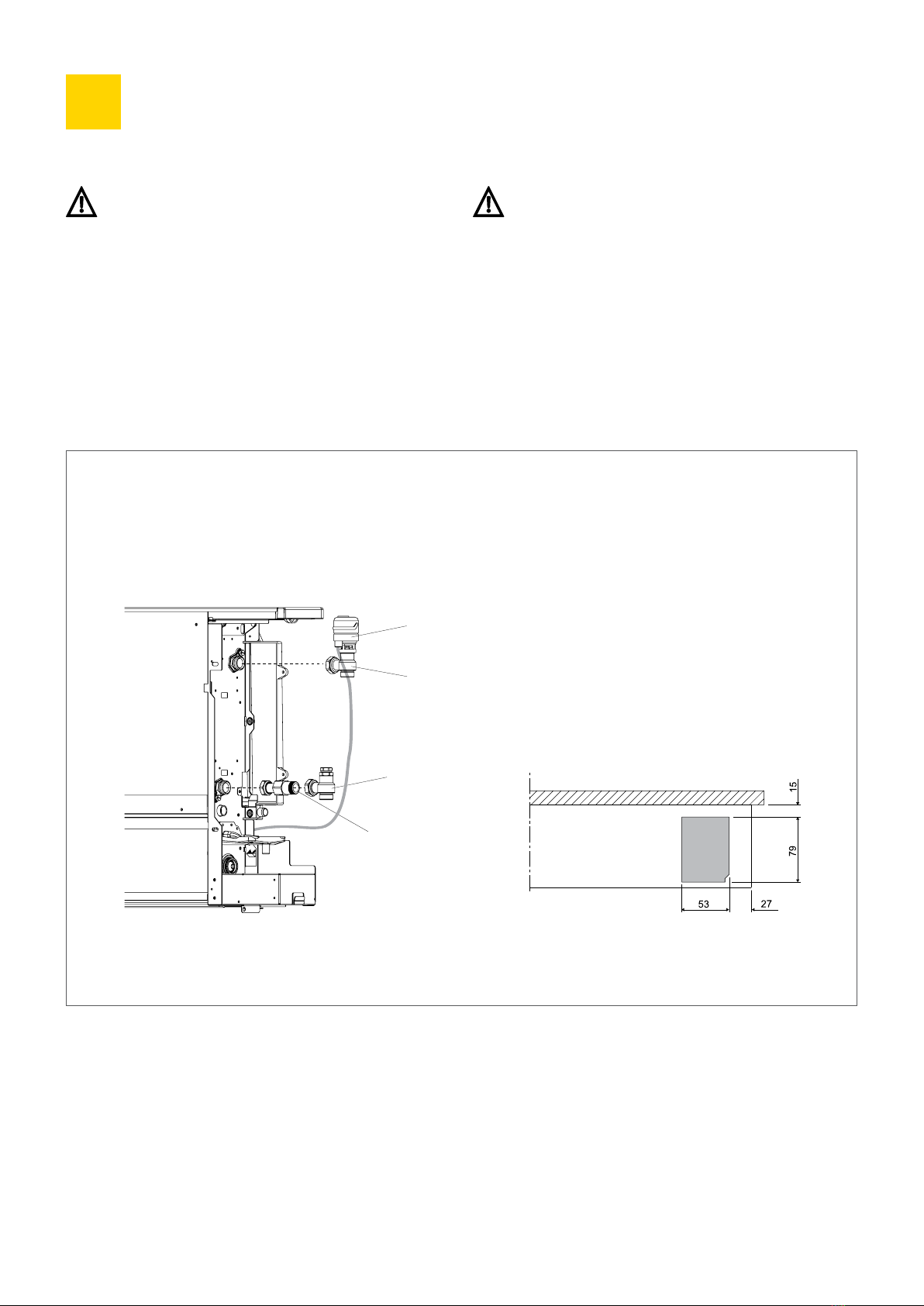
. Warnings
These instructions relate to the valve kits supplied with
the unit. The general instructions and basic safety rules
detailed in this manual should be followed.
For correct operating performance of this unit, the flow
and return pipework must be correctly fitted according to
the detail provided in these instructions.
Instructions -Way Valve
.
. -Way Valve Parts List
> x automatic valve with thermoelectric head for CA VS
& CA VSI models.
> x return with presetting for correct balancing of the system.
> x Connection /" Eurocone extention pipe (for use with pipe
connection from floor).
>Insulation pieces are supplied loose when the product is
supplied. These should be fitted to the flow and return valves
once the pipework connections have been made.
PLEASE NOTE: Valves are factory fitted but not tightened. For floor connections extension piece D (or similar) must be used
to clear outside edge of condensate tray.
Pipe Connection from Floor - with Optional /" EK Extension
AThermostatic head
B-way valve
CReturn valve connection
D/" Eurocone extension (optional – can be supplied as accessory)
A
C
B
D

ClimaAir18
Instructions -Way Valve (cont...)
.
Pipe Connection from Wall - with Optional ° Elbow Fitting
AThermostatic head
B-way valve
C° elbow fitting (optional – can be supplied as accessory)
DReturn valve connection
PLEASE NOTE: Valves are factory fitted but not tightened. For through-the-wall connections °elbow C (or similar)
should be used.
A
C
B
D
ClimaAir 19
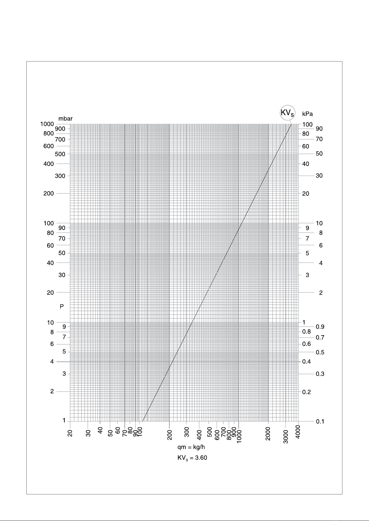
Pressure Drop Diagram
Pressure drop figures based on the -way valve fully open position.

ClimaAir20
. Return Valve Pre-Setting Screw Adjustment
The system can be balanced using the return valve(s) fitted to
the unit. The following procedure must be carried out for correct
regulation and balancing of the system:
Return valve pre-setting adjustment:
>Remove the top cap to reveal the adjustment mechanism.
>Use a screwdriver to loosen and remove the slotted pin inside
the central hexagonal recess.
>Use a mm Allen key to close the adjustment screw (A).
>Screw the slotted pin back in as far as it will go.
>Mark a reference point “x” aligned to the pin slot for adjustment
of the pin (B) .
>Use the screwdriver to open up the pin. The number of turns
should be determined from the ∆P-Q chart (C).
>Use the Allen key to open up the adjustment screw as far as it
will go (D).
>The pre-setting is now done and does not change when opening
and closing the adjustment screw with the Allen key. Replace
the cap.
Instructions -Way Valve (cont...)
.
Screwdriver
Screwdriver
Allen Key
Allen Key
Top Cap
This manual suits for next models
19
Table of contents
Other Merriott Heater manuals

Popular Heater manuals by other brands


Gasmate
Gasmate ALLURE instructions

Benchmark
Benchmark SYSTEMATE 2000 Series Design, installation and servicing instructions

Sunshower
Sunshower PURE XL installation guide

Chromalox
Chromalox ADH-005 Installation, operation and renewal parts identification

CTC Union
CTC Union CLATRONIC HL 3631 instruction manual

Consort
Consort LST500EWIFI Installation & Control Guide


