Merry Tiller G80 Setup guide

"The Original Since 1947"
"Works the Garden -
Not
the Gardener"
u.s.
Patent Numbers 2614474 and 2634666
OWNER'S
"INSTRUCTIONS
M~
UAL
AND
ILLUSTRATED
PARTS
LIST
~
,
/ •
SUBURBAN
·MERRY rlLLER
MODEL
GSO
•
o Manufactured
by
•
MERRY
MANUFACTURING CO.
o
Box
370t •
EDMONDS. WASHINGTON 98020
o o !' -
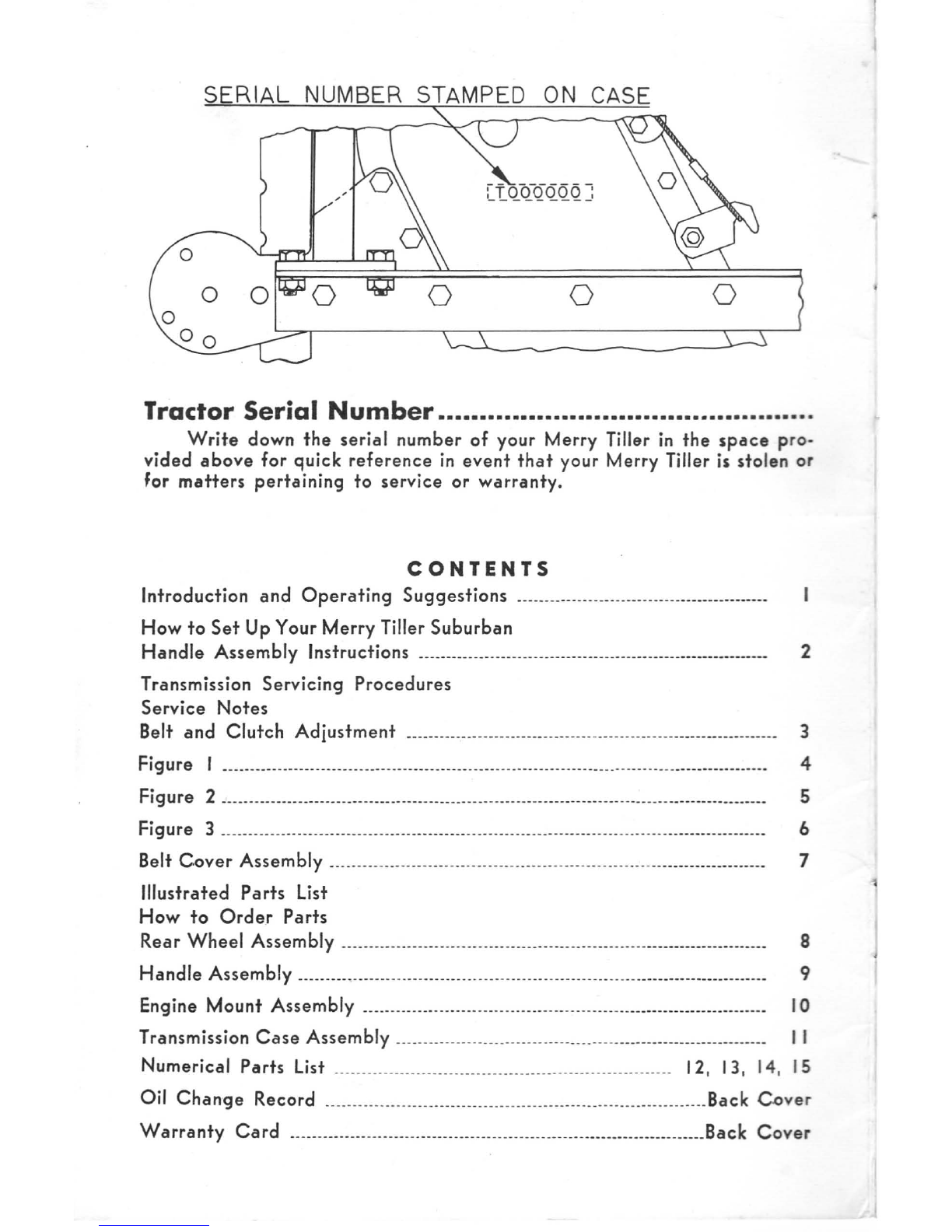
SERIAL
NUMBER STAMPED
ON
CASE
o
Tractor
Serial
Number
.............................................
.
Write
down
the
serial
number
of
your
Merry
Tiller
in
the
space
pro-
vided
above
for
quick
reference
in
event
that
your
Merry Tiller is
stolen
or
for
matters
pertaining
to
service
or
warranty.
CONTENTS
Introduction
and
Operating
Suggestions
_____________________________________________
_
How
to
Set
Up Your
Merry
Tiller
Suburban
Handle
Assembly
Instructions
________________________________________________________________
2
Transmission
Servicing
Procedures
Service
Notes
Belt
and
Clutch
Adjustment
___________
________________
___
_____________
_
_______
________
__ __
_____
3
Figure I
____________
____
__
__
____________________
___
_________________________________________
_________
_______
4
Figure 2
______________________________________________
___
_________________________
_
_________________________
5
Figure 3
__________________________
_
__
_
____________________
___
___________________
___
_________________________
6
Belt
Cover
Assembly
______________________________
__
__
__________________
___
___
_
_____________________
7
Illustrated
Parts
List
How
to
Order
Parts
Rear
Wheel
Assembly
_______
_
______________________
__
______________________________________________
8
Handle
Assembly
________________
_______
___
___
__
________________________________
__
______________
_______
9
Engine
Mount
Assembly
_____
__
__________________
_______
__
_____________________
__
______
___________
10
Transmission
Case
Assembly
__
__
____
__
__________________
_________
___
____________________________
I I
Numerical
Parts
List
_________
_
________________________
_
__________
_
_______________
_ 12, 13, 14,
15
Oil
Change
Record
__
__________
__
_____
_________
_____________
_________
___
__
___
____________
Back
Cover
Warranty
Card
__
__
______
_____________
_______
_________________________
_____________________
Back
Cover

INTRODUCTION
AND
OPERATING SUGGESTIONS
Your
Merry
Tiller
is
the
most
versatile
garden
tractor
ever
developed
for
the
home
gardener
and
does
a soil
preparation
job
second
to
none,
so
a
few
minutes
spent
in
studying
the
following
instructions
will
pay
many
dividends.
The
tiller
will
dig
deeper
and
move
forward
slower
by
pushing
down
on
the
handles,
and
it
will
go
ahead
faster
but
at
a
shallower
depth
by
raising
up
on
the
handles.
The
speed
of
the
rotors
is
controlled
by
the
use
of
the
throttle.
To
control
the
depth
of
tilling,
the
Merry
Tiller
must
be
operated
with
both
the
proper
throttle
speed
and
correct
up-and-down
hand
pressure
on
the
handles.
Raising
up
means
going
forward.
This
action
releases
the
grip
of
the
skid
in
the
soil,
allowing
the
Merry
Tiller
to
progress
ahead.
Pushing
down
means
slowing
down
or
even
standing
still. This
directs
the
skid
into
the
soil,
thus
holding
the
Merry
Tiller
back.
Adjust
throttle
for
desired
speed
of
rotors
.
When
a
person
is
first
learning
the
proper
use
of
the
Merry
Tiller,
it
is
not
unlikely
that
he
will
encounter
an
uneven
or
"bucking"
action
in
the
operation
of
the
machine.
A
little
practice
will
accustom
the
operator
on
how
to
overcome
this.
Never
push
on
the
machine
if
it
has
dug
itself
in
to
a
depth
of
six
to
ten
inches
in
order
to
get
it
to
move
forward,
This
is
ac-
complished
by
slightly
raising
up on
the
handles
and
tilting
the
machine
slowly
from
one
side
to
the
other.
To
acquire
the
knack
of
letting
the
Merry
Tiller
do
the
work
without
effort
on
the
part
of
the
operator,
we
offer
the
following
suggestions:
I.
Adjust
tail
skid
and
rear
wheels
so
the
handles
are
at
such
a
height
that
your
arms
hang
straight
down
to
contact
them.
Rear
wheels
should
be
removed
for
deep
talaqe
or
ease
of
turning
in
confined
areas.
Caution:
Keep
hands
clear
of
belt
while
engine
is
running.
2.
Operate
the
Merry
Tiller
at
about
half
throttle.
3.
Don't
hurry
the
job
-
proceed
at
a slow
walk
-
give
the
machine
time
to
do
its
job.
4.
Concentrate
on
keeping
your
arms
relaxed.
(There
is
a
natural
tendency
for
any
beginner
to
tense
up.)
Operation
actually
takes
very
little
effort.
Let
the
Tiller
do
the
work.
5,
When
tilling
on
sloping
ground,
turn
the
front
of
the
machine
up
hill
to
sufficiently
counteract
the
tendency
to
run
down
hill.
6.
For
best
results,
operate
at
reduced
throttle
settings
when
the
ground
is
extremely
hard
or
rough.
7.
When
cultivating,
raise
the
tail
skid until
the
handles
are
the
proper
height
as
described
in
Item
1
or
set
rear
wheels
in
position.
Pro-
ceed
at
a
slow
walk,
watching
the
rotor
as
it
tills
along
the
row.
S.
TIGHTEN
ALL NUTS
AND
BOLTS PERIODICALLY
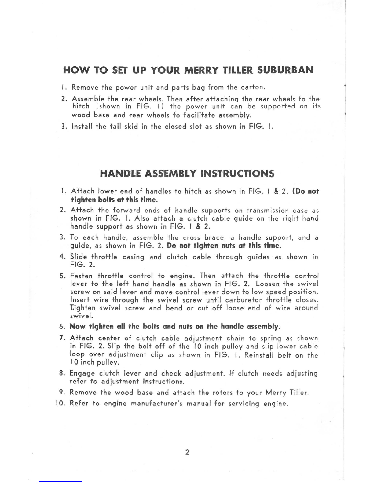
HOW
TO
SEll'
UP
YOUR
MERRY
TILLER
SUBURBAN
I.
Remove
the
power
unit
and
parts
bag
from
the
carton.
2.
Assemble
the
rear
wheels
. Then
after
attachinq
the
rear
wheels
fo
the
hitch
(
shown
in
FIG. I )
the
power
unit
can
be
supported
on its
wood
base
and
rear
wheels
to
facilitate
assembly.
3. Install
the
tail
skid
in
the
closed
slot
as
shown
in FIG. I.
HA'N'D1
LE
ASS
'E'MBLY INSTRUCTIONS
I.
Attach
lower
end
of
handles
to
hitch
as
shown
in
FIG. I & 2. (Do not
tighten bolts
at
this time.
2.
Attach
the
forwa
rd
ends
of
handle
supports
on
transmission
case
as
shown
in
FIG. I. Also
attach
a
clutch
cable
guide
on
the
right
hand
handle
support
as
shown
in
FIG
. 1 & 2.
3.
To
each
handle,
assemble
the
cross
brace,
a
handle
support,
and
a
guide,
as shown
in
FIG. 2.
Do
not tighten
nuts
at
this
time.
4.
Slide
throttle
casing
and
clutch
cable
through
guides
as
shown
in
FIG. 2.
5.
Fasten
throttle
control
to
engine.
Then
attach
the
throttle
control
lever
to
the
left
hand
handle
as
shown
in
FIG
. 2. Loosen
the
swivel
screw
on
said
lever
and
move
control
lever
down
to
low
speed
position.
Insert
.
wire
through
the
swivel
screw
until
carburetor
throttle
closes
.
T.ighten swivel
screw
and
bend
or
cut
off
loose
end
of
wire
around
swivel.
6. Now tighten all the bolts and nuts
on
the handle assembly.
7.
Attach
center
of
clutch
cable
adjustment
chain
to
spring
as
shown
in FIG. 2. Slip
the
belt
off
of
the
10 inch
pulley
and
slip
lower
cable
loop
over
adjustment
clip as
shown
in
FIG. I. Reinstall
belt
on
the
10 inch
pulley
.
8.
Engage
clutch
lever
and
check
adjustment
. H
clutch
needs
adjusting
refer
to
adjustment
instructions
.
9.
Remove
the
wood
base
and
attach
the
rotors
to
your
Merry
Tiller.
10.
Refer
to
engine
manufacturer's
manual
for
servicing
engine.
2
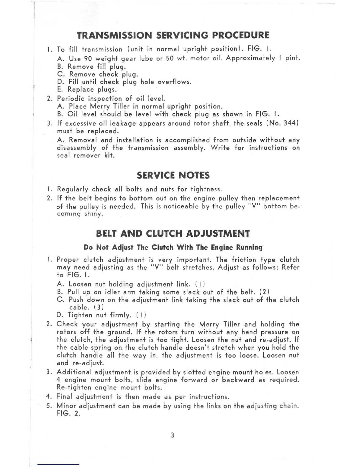
TRANS,
MISSION
SERVICING PROC'
EDU'RE
I.
To fill
transmission
(unit
in
normal
upright
position).
FIG. I.
A. Use
90
weight
gear
lube
or
50
wt.
motor
oil.
Approximately
1
pint.
B.
Remove
fill
plug
.
C.
Remove
check
plug.
D.
Fill until
check
plug
hole
overflows.
E.
Replace
plugs.
2.
Periodic
inspection
of
oil
level.
A.
Place
Merry
Tiller in
normal
upright
position.
B.
Oil
level
should
be
level
with
check
plug
as
shown
in
FIG.
I.
3. If
excessive
oil
leakage
appears
around
rotor
shaft,
the
seals
(No.
344)
must
be
replaced.
A.
Removal
and
installation
is
accomplished
from
outside
without
any
disassembly
of
the
transmission
assembly.
Write
for
instructions
on
seal
remover
kit.
SERVICE N'
OTES
I.
Regularly
check
all
bolts
and
nuts
for
tightness.
2. If
the
belt
begins
to
bottom
out
on
the
engine
pulley
then
replacement
of
the
pulley
is
needed.
This
is
noticeable
by
the
pulley
"V"
bottom
be-
coming
shinY.
BElT AI
ND
CLUrCH
ADJU5rM
'ENT
Do
Not Adjust
The
Clutch With
The
Engine
Running
I.
Proper
clutch
adjustment
is
very
important.
The
friction
type
clutch
may
need
adjusting
as
the
"V"
belt
stretches.
Adjust
as
follows:
Refer
to
FIG.
I.
A.
Loosen
nut
holding
adjustment
link.
(I)
B. Pull
up
on
idler
arm
taking
some
slack
out
of
the
belt.
(2)
C.
Push
down
on
the
adiustment
link
taking
the
slack
out
of
the
clutch
cable.
(3)
D.
Tighten
nut
firmly.
(I)
2.
Check
your
adjustment
by
starting
the
Merry
Tiller
and
holding
the
rotors
off
the
ground.
If
the
rotors
turn
without
any
hand
pressure
on
the
clutch,
the
adjustment
is
too
tight.
Loosen
the
nut
and
re-adjust.
If
the
cable
spring
on
the
clutch
handle
doesn't
stretch
when
you
hold
the
clutch
handle
all
the
way
in,
the
adjustment
is
too
loose.
Loosen
nut
and
re-adjust.
3.
Additional
adjustment
is
provided
by
slotted
engine
mount
holes.
Loosen
4
engine
mount
bolts,
slide
engine
forward
or
backward
as
required.
Re-
tighten
engine
mount
bolts
.
4. Final
adjustment
is
then
made
as
per
instructions
.
5.
Minor
adjustment
can
be
made
by
us
in
g
the
links on
the
adju
sting
chain
.
FIG.
2.
3

TAIL
SKID
FIGURE I
R/H
S
IDE
VI
EW
4
o 0

J
FIGURE
2
REAR
V
IE
W
5

FIGURE 3
2659
2647

\
.J
BELT
COVER ASSEMBLY
'
Herpful
Hint
When
installing
the
Brackets on
the
Unit
do
not
tighten
capscrews
until
step
3
is
completed
below.
Assembl.y
I.
Attach
No.
2659
Bracket
on
Case
Fig.
3.
2.
Attach
No.
2648
Bracket
on Engine
Mount
Fig. 3.
3.
Mount
No.
2658
Cover
over
the
Brackets,
and
No.
2647
Belt
Release.
Fig. 3. Using 3 No.
2560
Capscrews,
3 No. 2661 Locknuts
and
one
No.
400
Washer
on
the
Locknut
side
of
the
No
2647
Belt
Release.
(To
protect
the
slots from
damage
.)
COVER ASSEMBLY
2662
.
-2560
~
-400
2
-2661
2 6 5
7
26
59
26
6
1
-
~
-
t.
2
56
0
--
!!
-
~
6'

ILLUSTRATED PARTS
LIST-MODEL
G80
HOW
TO
ORDER
PARTS
I.
THE MODEL NUMBER
OF
YOUR MERRY TILLER MUST
BE
GIVEN
WHEN
ORDERING
PARTS
. THE MODEL NUMBER
IS
INDICATED
ON
THE
UPPER
L.
H.
CORNER
OF
HANDLE
CROSS BRACE NEXT TO THE MERRY TILLER
OVAL.
MODEL
NO.
2.
HOW
TO FIND THE CORRECT NUMBER
OF
PARTS
YOU NEED.
Refer
to
the
following
pages
illustrating
parts
and
locate
the
part
needed
in
the
correct
exploded
view
and
note
the
part
number.
All
parts
shown
that
have
part
numbers
can
be
purchased
separately.
After
the
part
number
has
been
identified,
refer
to
the
fol-
lowing
Parts
List,
pages
12, 13, 14, 15,
where
these
parts
are
listed
in
numerical
order.
,
• • * * • •
REAR
WHEEL ASSEMBLY
2479
10.3
3
I
~
~
--'
-r
8

HANDLE
ASSEMBLY
2620
9
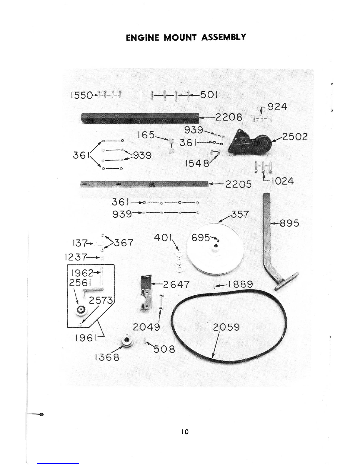
ENGINE MOUNT
ASSEMBLY
361-.0-
0- 0- 0
939-
,,
-
e
-¢-
~
/357
----~
137- :
>367
401\
695-:. "
1237-
!i
1962-
'
2561
\
~
2573
';;
'-
~'
~
tr
2647
.
-1889
~I
r
~~
2049
1961 P
1368
10
502
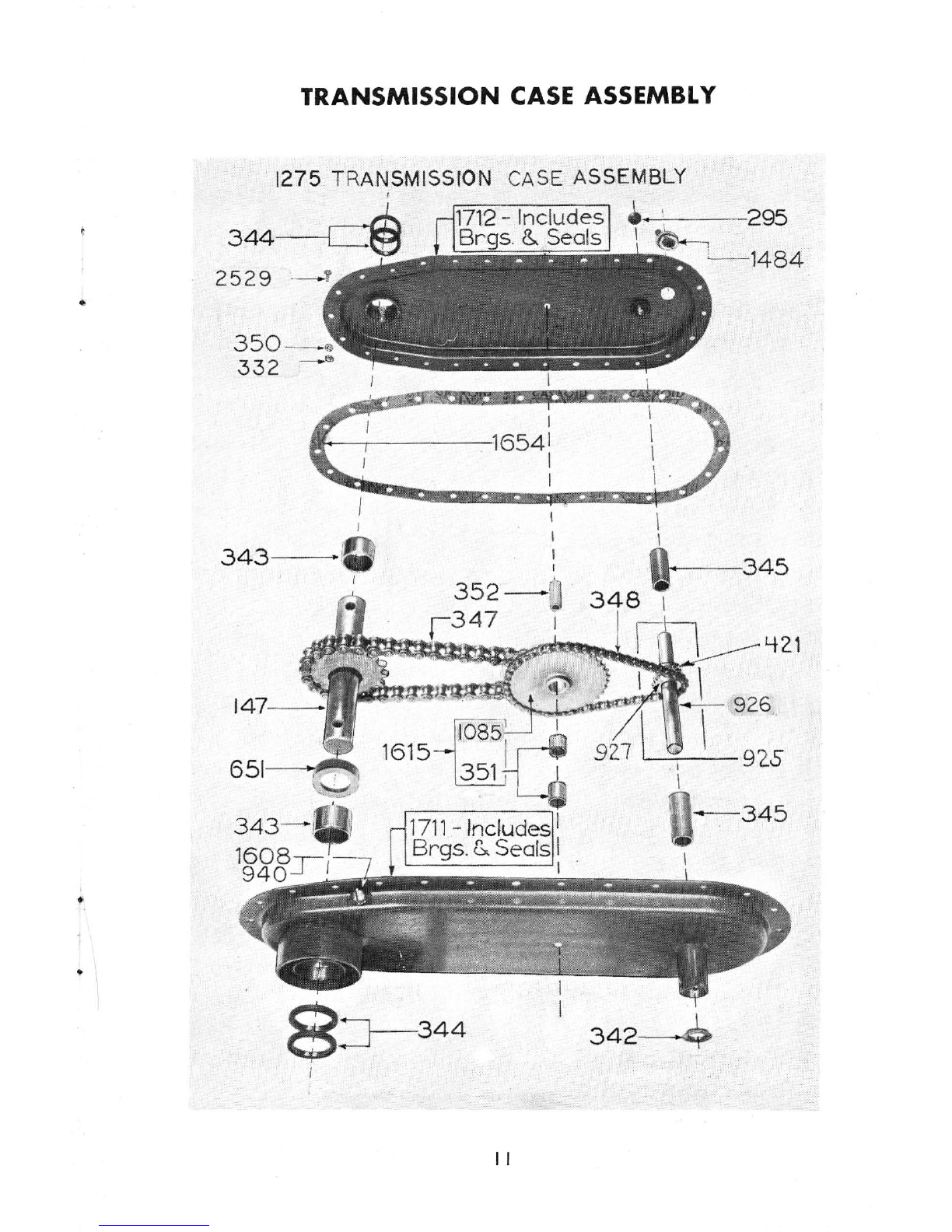
TRANSMISSION
CASE
ASSEMBLY
1275 TRAN
SM
ISSION CASE ASSEMBLY
,
344
-
--j
."-;,ilI
I
11f+-----.-----1
654
i
. I
I
343
-----
-t_
I
651
-~'
8:J--
344
"
1.........:-
--
295
,
I .
\
\
1484
348
~
-.
--34
5
342
~
MERRY
TILLER
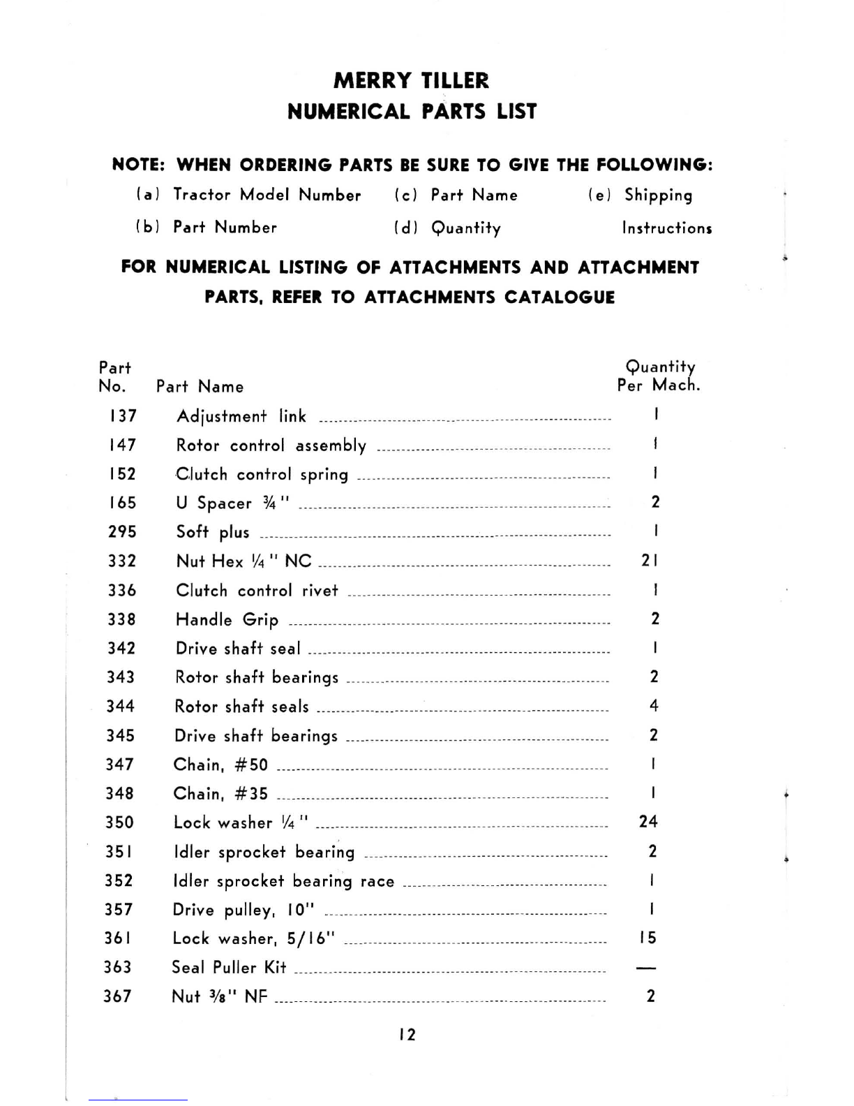
NUMERICAL
PARTS
LIST
NOTE: WHEN ORDERING
PARTS
BE
SURE
TO
GIVE
THE
FOLLOWING:
(a)
Tractor
Model
Number
(c)
Part
Name
(e)
Shipping
(b)
Part
Number
(d)
Quantity
Instruction,
FOR
NUMERICAL LISTING OF ATTACHMENTS AND ATTACHMENT
PARTS,
REFER
TO
AnACHMENTS
CATALOGUE
Part
No.
Part
Name
137
Adjustment
link
147
Rotor
control
assembly
_____
__
___
__ __
_
_____
_
_______
___
_________
_
______
_
Q u
antity
Per
Mach.
152
Clutch
control
spring
___________________
_
______________
___
_______________
I
165 U
Spacer
¥.!"
__________
_
__
______
__ __
___
__
_____________
___
__
____
_______
_
___
__
_ 2
295
Soft
plus
__
_
___
__
_____________________
_
______
_
___________
__ __ __
-
--------------
---
332
Nut
Hex
if4"
NC
_
____________
__
__________
_
__
_______________
_____
_
__
_
________
21
336
Clutch
control
rivet
________
_
_____
_
_____
___
___________
____
___
_
_____
_
___
__
_
338
342
343
344
345
347
Handle
G r
ip
_________
_
__ __
_
____
___
_______________
___
_
__
___
________
---
---
------
Drive
shaft
sea
I
____
____
__
__ __
_
__
_
__
_
__
____
_
__________
_
________
__
__
__
__
_
_____
_
Rotor
shaft
bearings
--------------------
-
------
-
-----------
-
---
--
----
--
--
-
Rotor
shaft
seals
__
_________________
____
__
_
__
_
_______
____
_
__
_
_________
______
_
Drive
shaft
bea
ri
ngs
--
-
--
--------
--
-
--
-
---
-
--
---
----
---------
-----
---
-----
Chain,
#50
_____ _____
__
__
____
__
_____
____
______
_
____________
_
__
_
_______________
_
348
Cha
in, #
35
___
_____
____
_____
_
___
____
__
____
_____
__
_
___
__
___
_
____
__
--
---------
__
_
2
2
4
2
350
Lock
washer
if
4"
___
_
___________
_____
___
________
___
__
__
____
__
___
_
_______
_
____
24
351
Idler
sprocket
bearing
____
___
____
_____
_
__
__ __
_____
_
____________
_
___
____
_ 2
352
Idler
sprocket
bearing
race
__
__
____
____
___
____
_
___
__________
___
__
_
__
_
357
Drive
pulley
, I
0"
____
_
___
___
____
__
____
___
__
__
______
__
____
______________
---
_
361 Lock
washer,
5/
16"
__
___
__
___
_
_______
__
____
_____
__
__
______
__
___
___
___
____ 15
363
Seal
Puller Kit
_____
_________
__
_____
_
___
__
_
___
_
__
___
____
____________
_-__
_____
__
367
Nut
l/S" NF _
___
____
_________
___
_
__
_
_________
_
____
_
____
_________
___________
____
_ 2
12

Part
No.
Part
Name
396
400
401
421
501
508
Lock
Washer
3/
S" ____________ __
_______
_____
__
__
______
_
____________
_
Washer
Flat 1/4"
___
______
___
___
__
_
______
___
Drive
shaft
washer
5/
S"
_____
-
__
_
__
____ _ _
______
__
_____
__
_____
______
_
Roll
Pin 1/4" X
1_
Y4"
_____
___
_____
______
__
--
-
____
_
__
_
___
_
__
__
___
_
Cap
screw
5/16"
NF
x 21
/2"
____________________
_
_________
_
Engine pulley key _
______
___
_________
_
___
_
651
Spacer-Rotor
shaft
_
____
___
____
_
__
_
__
______
__
__
__
_
______
__
_
_____
__ __
__
695
Set
Screw
5/16"
NC x
3/.1"
_
___
____
___
__
__
__
_
_________
__
___
__
_____
_
895
924
925
926
Rear Skid
____
_
_____
_
__________
____
_______
__
__
_
___ ___
_
___
_
___
_
__
------
-
--
--
-- --
---
Hairpin
cotter
__
____
_
______
______
__
_
__
__
____
__
___
__
___
-
--
-
----
-- - -------
Drive
shaft
w/
sprocket
_
_________
__
_____
___
__
___
__
__ __
_____
___
____
__
__
Drive
shaft
w/o
sprocket
_______
_
__
___. _
__
___
__
__
____
___
_
927
Sprocket
-Drive
shaft
__
__
____
939
940
1024
1033
1080
1085
1237
1275
1368
1484
1539
1548
1550
1608
1615
1654
Nut
5/16"
Check
plug
gasket
5/16"
ID
__
_
Pin,
3Ja"
x
21/4"
_
__
_
__
_
__
____
__ __
____
_._.
__
.
__ __
_.._
__
..
___
._
..._.._..__..
__
Wheel,
10
x
1.75
..
_______
_. .. _ _
Nut, sq.
3/
S"
NC
__
___..._
__
_
__
__
___
__
Idler
sprocket
w/o
bearing
___
___
_.._
..
.
__
.
____
__
._
__
_._
Spring-compression idler arm
__ __
.___
__
_._
__
.
Replacement
case
assembly ._
__
___...
___
___
._
.
__
..
___
_
Engine pulley,
%"
bore
_________
__
..
__
_..
__
_.. ___.
___
.
Oil filler plug
__
.
___
...__
._
___
__
_ __
____
___
Nut -Keps-I
032
Screw,
cap
5/16"
NF
x
1"
__ ____
Screw-cap
hx
hd.
5/16"
NF
x
1-1/2
" Pltd.
__
Screw, rd. Hd.
5/16"
NF
x
1/
2"
___
_ _
Idler
sprocket
assembly with brgs.
Gasket
__
__
__
__________
__
__
__
1711
Case
assy. -L.H.
w/brg.
&
seals_
1712
Case
assy. -R.H. w
/brg.
& seals _
13
Quantity
Per Mach.
2
I
3
4
I
5
15
I
5
2
2
.I
2
2
4
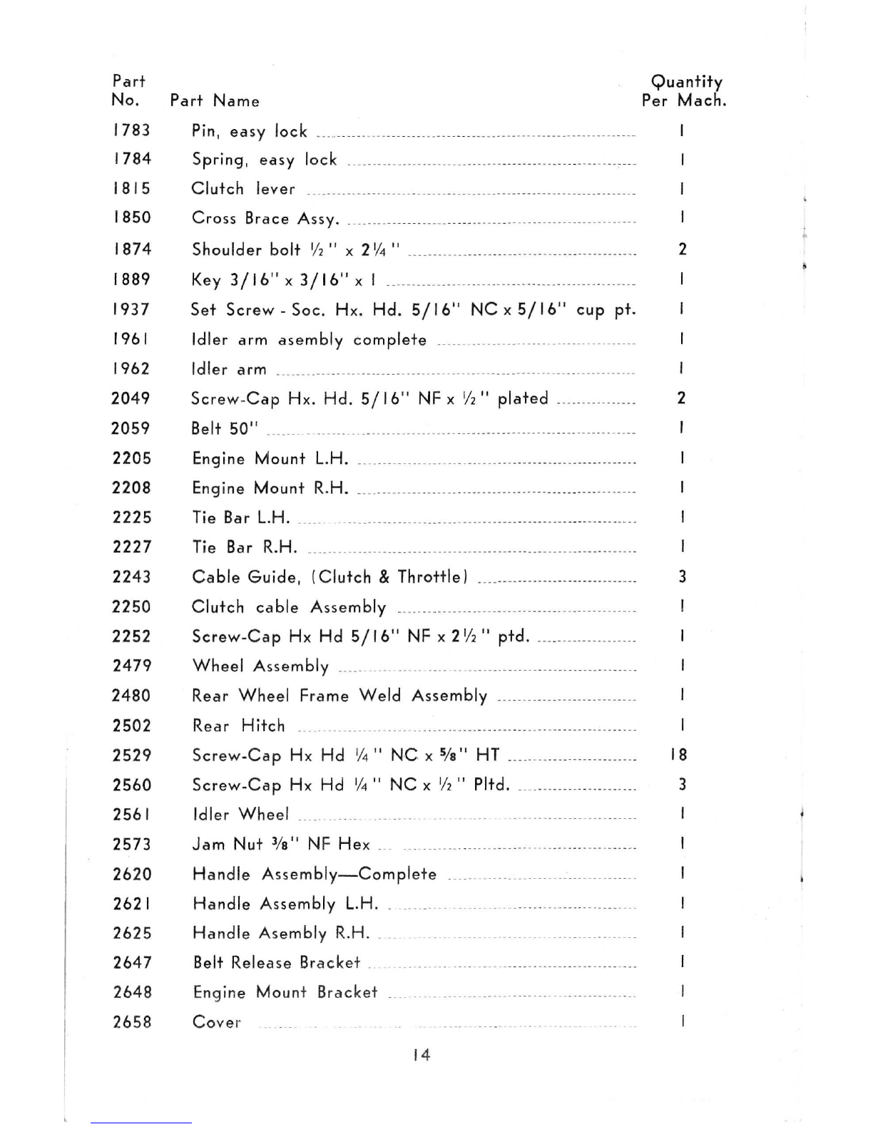
Part
No.
Part
Name
1783
1784
1815
1850
1874
1889
Pin,
easy
lock
__
_
Spring,
easy
lock
Clutch
lever _
__
___
_
___
____
__
__
_
___
_____
________
____
_________
__
__
_
_______
____
_
Cross
Brace
Assy
. _
________
_____
____
__
___
_._
_____
_
__
________
__
___
_
____
_
__
_
Shoulder bolt 1
12
" x 2
\/4
"
___
_______
____
__
_
_________
__ __
_______
____
___
_
Key
3/16"
x
3/16"
x I
________
____
___
___
_
__
______
__
__
_
____
__
__
_____
_
1937
Set
Screw
-Soc. Hx. Hd.
5/16"
NC
x
5/16
"
cup
pt.
1961
Idler arm
asembly
complete
_
_____________
_
__
__
__
___
____
_____
___
_
1962
2049
2059
Idler arm _
__________
___
_
__
_
_______
__
___
_
__
__
____________
_
____ ____
_____
__________
_
Screw-Cap
Hx. Hd.
5/16"
NF
x 1/2"
plated
_____
________
__
_
Belt
50"
_
_____
_______
__
__
__
_
____________
__
___
_
__
_0
__ __
_____
______
__
_
__
___
_
__
_ _ _ _ _
2205 Engine Mount L.H.
____
______
____ ____
___
_
__
_
___________
__
__
____________
_
__
_
2208
2225
2227
2243
Eng
ine Mount R.H. _
___
___
____
_
___
_
____
_
___________
____
_______
__
____
______
_
Tie Bar L.H.
___
_
____
__
_____
__
_____
_
____
__
_
___
_
___ ___
_
___
_
____
___
__
__
_______
___
Tie Bar R.H.
______
__
_____
__
___
____
_
__
__
__
_
__
___
___
__
____________
_
_______
____
._
Cable
Guide
,
(Clutch
& Throttle) __
__
-
_______________
___
___
__
_
__
_
2250
Clutch
cable
Assembly _
__
_____
__
__
__
_
___
_
__
_____.
__
_____________
__
___
_
2252
Screw-Cap
Hx Hd
5/16"
NF
x 2 1
/
2"
ptd.
___
_______
__
_
___ ___
_
2479
Wheel
Assembly
_____
_.
____
_.
___
__
__
__
___
_
__
_._
___
___
_
___
___
_
___________
_
2480
Rear
Wheel
Frame
Weld
Assembly _
__ __
___
__
_________
_
_______
_
2502 Rea r Hitch _
__
____
_____
____
___
_
________
___
._
__
__
_
___
_______
___
__
__
___ ___
__
_
2529
2560
2561
2573
2620
2621
2625
2647
2648
2658
Scr
ew-Cap
Hx Hd 1
/4"
NG
x
Sfs"
HT
_
____
___
__
_
__________
_
___
_
Screw-Cap
Hx Hd 1
/4
"
NC
x 1
12
" Pltd. _
__
_
_______
_
____
_
__
____
_
Idler
Wheel
_
__
----.
-----
---
-.-
--
-- -- --
Jam
Nut
3/
S" NF Hex _
Handle
As
s
embly-Complete
____
_____
_____
_..
______
__.
_____
_____
_
Handle
Assembly
L.H
.
__
__
__
___ ___
_____
__
Handle
Asembly R.
Ho
__
Belt Release
Br
ac
ket _
En
gine Mount
Br
acket
Cov
er
14
Quantity
Per Mach.
2
2
I
3
18
3
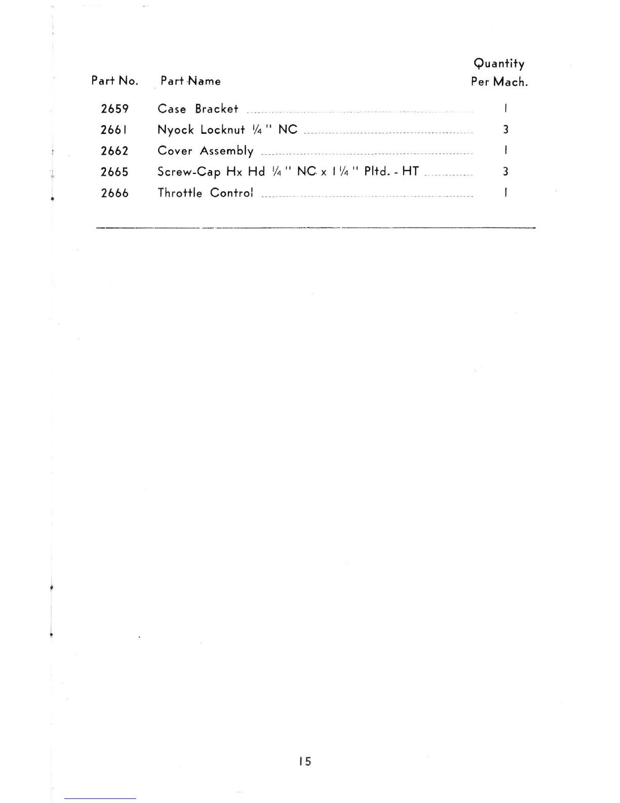
Part
No.
Part
Name
Quantity
Per
Mach.
2659
Case
Bracket
2661
2662
2665
Nyock
Locknut
'/4
"
NC
_
_________
__
___
_____
________
___
___
__
Cover
Assembly
___
______
__________
_
__
_
____
_
__
_____
_______________
__
_
_____
__
Screw-Cap
Hx
Hd
'
/4
"
NC
x 1'
/4
" Pltd. -HT __._
___
..___
2666
Throttle
Control
_____
..
__
_
___
__
_
_______
_ ._
___ ___
_.
__
_
__
__
_
__
____
.
15
3
3

OIL
CHANGE
RECORD
16

IRJMMMIMM~
WAR
RAN
TV
CE
RT
I
Fie
ATE
M~~~
:J0R
ONE
YEAR
from purchase
date,
Merry Manufacturing
Company
will
replace
for
the
original purchaser,
FREE
OF
CHARGE, any
part
or
parts
found, upon
examination
at
our
factory
at
Edmonds, Washington, to
be
defective
under normal
use and service, on
account
of
defects
in
material
or workmanship.
ALL
TRANSPORTATION CHARGES ON
PARTS
SUBMITIED
FOR
REPLACEMENT
UNDER
THIS WARRANTY
MUST
BE
BORNE
BY
PURCHASER.
THIS WARRANTY shall
not
be
effective
If
the
product
has been
subject
to
misuse,
negligence or accident, nor if
the
product
has been
repaired
or
altered
outside
of
our Edmonds Factory, or Authorized. Service Station,
in
any
respect
which,
in
our
judgment,
affects
its condition
or
operation.
FOR
COMMERCIAL
USE,
WARRANTY
LIMITED
TO
THIRTY
DAYS.
The
engine
is
covered under
separate
Warranty
from Engine Manufacturer.
MERRY
MANUFACTURING
COMPANY
Th;s
Warranty
shall
be
e
ff
e c t i v e
only
providing
ottached
Warranty
Card
is
properly
filled
oul
and
returned
to
Merry
Manu-
facturing
Co.
ot
time
of
purchase.
SAVE THIS
WARRANTY
CARD
Fill
in
this information
and
retain
for
your own
record.
Serial No...............................................
IMPORTANT
(Not
engine Serial No.)
Model No..............................................
To
make
Warranty
valid.
fill
in
and
return
attached
card.
Purchased
from ..._.........
________
.
_____
.
__
..
___
..
.'
Date
Purchased
..
______________________
..
__
...
____
..
For
Prompt
and
Accurate
Service
Serial
Number
must always
be
given
when
ordering
parts
or
writing
for
any
information.
r-
)
Merry
Manufacturing
Co
•
Box
370
Edmonds, Wash.
98020

Be
sure
to
fill
in
the
attached
Warranty
Card
below
and
mail
it
immediately!
WARRANTY CARD
Please print carefully
In
IDk
Serial No.__
_____
__
__
__
_______
_
___
Model No._
___________
_
___________
Date Purchased
________________
_
I
Not
engine
S.ri
,al No.!
De
aIer
Pu
rch
ased f
rom
____
___________
__
___________
_
____________________________________________________________
_
, Address
______
____
________________________
__
____________________________
State
________________
Zip
_______________
_
OwnerI s Name _
________
__
_______________
_
____
_
_______________________________________________________________________
_
i Add
re
ss
----
-
---------
----
_
---
--
-----
--
------
--
----
----
---
:..
--
---
-
----
---
_
--
-
-----
..
-----
-
---
-----
----
----
-
----------
_____
_
I
I
Town
----
--
-
------------
--
----------------
--
-----
County
----
---
--
-
--------
--
------
--
--
-
-----
State
----------------
Please Check One of the Following:
Suburban 0 Rural 0 Commercial 0
Table of contents
Popular Lawn And Garden Equipment manuals by other brands

Sunforce
Sunforce SOLAR user manual

GARDEN OF EDEN
GARDEN OF EDEN 55627 user manual

Goizper Group
Goizper Group MATABI POLMINOR instruction manual

Rain Bird
Rain Bird 11000 Series Operation & maintenance manual

Cub Cadet
Cub Cadet BB 230 brochure

EXTOL PREMIUM
EXTOL PREMIUM 8891590 Translation of the original user manual


Vertex
Vertex 1/3 HP Maintenance instructions

GHE
GHE AeroFlo 80 manual

Land Pride
Land Pride Post Hole Diggers HD25 Operator's manual

Yazoo/Kees
Yazoo/Kees Z9 Commercial Collection System Z9A Operator's & parts manual

Premier designs
Premier designs WindGarden 26829 Assembly instructions

Snapper
Snapper 1691351 installation instructions