Mesa 4P20 User manual

4P20 PC/104-PLUS POE
POWER SUPPLY
1.0

This page intentionally not blank
-

iii
Table of Contents
GENERAL . . . . . . . . . . . . . . . . . . . . . . . . . . . . . . . . . . . . . . . . . . . . . . . . . . . . . . . . . . 1
DESCRIPTION ................................................. 1
HARDWARE CONFIGURATION . . . . . . . . . . . . . . . . . . . . . . . . . . . . . . . . . . . . . . . . . 2
+-12VENABLE ................................................. 2
CONNECTORS . . . . . . . . . . . . . . . . . . . . . . . . . . . . . . . . . . . . . . . . . . . . . . . . . . . . . . 3
CONNECTOR LOCATIONS AND DEFAULT JUMPER POSITIONS . . . . . . . . 3
ETHERNET CONNECTORS . . . . . . . . . . . . . . . . . . . . . . . . . . . . . . . . . . . . . . . 4
5V AUX OUT . . . . . . . . . . . . . . . . . . . . . . . . . . . . . . . . . . . . . . . . . . . . . . . . . . . 4
FAUX IN . . . . . . . . . . . . . . . . . . . . . . . . . . . . . . . . . . . . . . . . . . . . . . . . . . . . . . . 4
RAUXIN ...................................................... 4
PC/104 CONNECTORS . . . . . . . . . . . . . . . . . . . . . . . . . . . . . . . . . . . . . . . . . . 5
OPERATION . . . . . . . . . . . . . . . . . . . . . . . . . . . . . . . . . . . . . . . . . . . . . . . . . . . . . . . . 6
POE OPERATION . . . . . . . . . . . . . . . . . . . . . . . . . . . . . . . . . . . . . . . . . . . . . . . 6
AUX INPUT OPERATION . . . . . . . . . . . . . . . . . . . . . . . . . . . . . . . . . . . . . . . . . 6
REFERENCE . . . . . . . . . . . . . . . . . . . . . . . . . . . . . . . . . . . . . . . . . . . . . . . . . . . . . . . . 7
SPECIFICATIONS . . . . . . . . . . . . . . . . . . . . . . . . . . . . . . . . . . . . . . . . . . . . . . . 7

4P20 1
GENERAL
DESCRIPTION
The 4P20 is a Power-Over -Ethernet power supply that allows remote operation of
low power PC/104-PLUS stacks. The 4P20 provides a feed-through POE tap so that the
remote system can get power and Ethernet communication from a single CAT5 cable up
to 100 meters long. The 4P20 supplies 5V and limited amounts of +- 12V power to the
stack. +-12 Volt outputs can be disabled if not required.
An auxiliary power input can be used if POE is not available, or for battery backup
/ failover type applications. Output power is isolated from POE and AUX power. Power
connectors compatible with pluggable screw terminals are provided for the AUX and +5V
power. +5V and +- 12V are wired to the PC/104 and PC/104 PCI connectors.

4P20 2
HARDWARE CONFIGURATION
+/-12V DISABLE
The 4P20 only has one hardware option, + /-12V disable. This option is set by th e
position of jumper W1. When W1 is in the up position (towards the PCI connector), the
+12Vand -12V power supplies are enabled.WhenW1isinthedown position (towards the
PC/104 connector), the +12 and -12V power supplies are disabled.
4P20 3
CONNECTORS
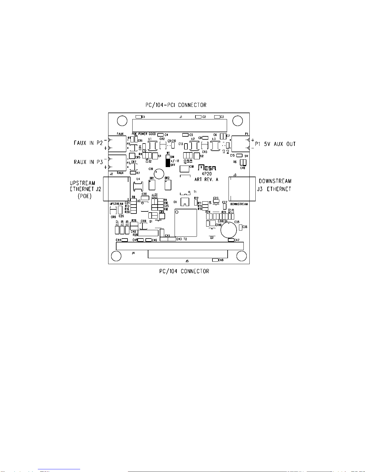
CONNECTOR LOCATIONS AND DEFAULT JUMPER POSITIONS

4P20 4
CONNECTORS
ETHERNET CONNECTORS
J2 and J3 are the 4P20's feedthrough Ethernet connectors. J2 is the upstream
connector that connects to a POE enabled HUB. J3 is the downstream connector that
connects (usually via a short patch cable) to the PC104-PLUS CPU’s Ethernet port.
5V AUX OUT
P1 is an alternate connection to the 4P20's 5V output. It can be used as a
convenient power tap for non-PC/104-plus devices.
P1 PINOUT
PIN1 5V
PIN2 GROUND
FAUX IN
If POE power is not available, the FAUX input allows the 4P20 to be powered from
anexternalsource.TheFAUXinput share the same current limitingasthePOEinput.This
limits the lowest voltage the 4P20 will operate with full power out. The FAUX input can
range from +36 to +60 VDC.
P2 PINOUT
PIN1 +36 to +60 VDC
PIN2 INPUT COMMON
RAUX IN
Like the FAUX input, the RAUX input allows the 4P20 to be powered from an
external source. Unlike the FAUX input, the RAUX input does not have an input current
limit and therefore has a larger input volatge range. The RAUX input can range from +18
to +60 VDC.
PIN1 +18 to +60 VDC
PIN2 INPUT COMMON

4P20 5
CONNECTORS
PC/104 CONNECTORS
The 4P20 connects its GND,5V,+12V and -12V outputs to the standard PC/104,
PC104-PLUS power pins so that the stack can be powered without additional cables
J1 CONNECTOR PINOUT (PC/104-PLUS CONNECTOR)
GND = A5,A10,A14,A20,A24,A28,B3,B9,B13,B18,B23
GND = C4,C7,C12,C16,C22,C26,D5,D11,D15,D20,D25,D27
+5V = A22,A26,B21,B27,C1,C24,C28,D2
+12V = A29
-12V = A30
J4 CONNECTOR PINOUT (PC/104 8 BIT CONNECTOR)
GND = B1,B31,B32
+5V = B3,B29
+12V = B9
-12V = B7
J5 CONNECTOR PINOUT (PC/104 16 BIT EXTENSION)
GND = C0,D0

4P20 6
OPERATION
POE OPERATION
Power over Ethernet is a system that allows low powered remote devices to get
power over standard Ethernet wiring. The 4P20 is a POE tap for low power PC/104 and
PC/104-PLUS systems. The 4P20 supplies 11W total of 5V and +- 12V power. This power
is electrically isolated from the power delivered via the Ethernet wiring.
Normally, the 4P20 is put in series with the Ethernet wiring coming from a POE
capable hub and the remote system, with the 4P20s UPSTREAM connector (J2)
connected to the hub, and the DOWNSTREAM connector (J3) connected with a short
CAT5 patch cable to the CPU or other remote PC/104 card.
AUXILIARY INPUT OPERATION
In addition to running from a POE source, the 4P20 can function as an isolated
power supply for a PC/104 stack with and external 18 to 60V power source. If an external
source is supplied to the RAUX input, it has dominance over the POE input, shutting down
thePOEinputand using the RAUX input exclusivelyas the powersource.Thisallowsdual
sources to coexist, for example battery and POE. Note that the 4P20 can seamlessly
shiftfromPOEpowertoRAUX power, but thereverseisnottrue,asthePOEsystemtakes
time to go through its detection, classification, and startup phases, when it starts to power
a load.

4P20 7
REFERENCE
SPECIFICATIONS
POWER MIN MAX NOTES:
5V OUTPUT VOLTAGE 4.75V 5.25V
5V OUTPUT CURRENT --- 2A 1
+12V OUTPUT VOLTAGE 11.7V 12.3V
+12V OUTPUT CURRENT --- 200 mA 1
-12V OUTPUT VOLTAGE -11.7V -12.3V
-12V OUTPUT CURRENT --- 100 mA 1
ISOLATION VOLTAGE --- 500 VDC 2
NOTE1:Totaloutputpowernottoexceed11WwithPOE, 13WwithRAUXorFAUXinputs
NOTE 2: Isolation between input and output, that is POE,RAUX,FAUX and 5V,+/-12
Table of contents
Popular Power Supply manuals by other brands


e+p
e+p C 3002 instruction manual

Pulsar
Pulsar PSBEN 10A12C manual

Pepperl+Fuchs
Pepperl+Fuchs PSU1100-J1-AC Series instruction manual

Linear Technology
Linear Technology DC1601B Demo Manual

Signtex
Signtex CRSAC-MM Series Installation instructions and owner's manual

Transition Networks
Transition Networks SPS-1872-CC user guide


