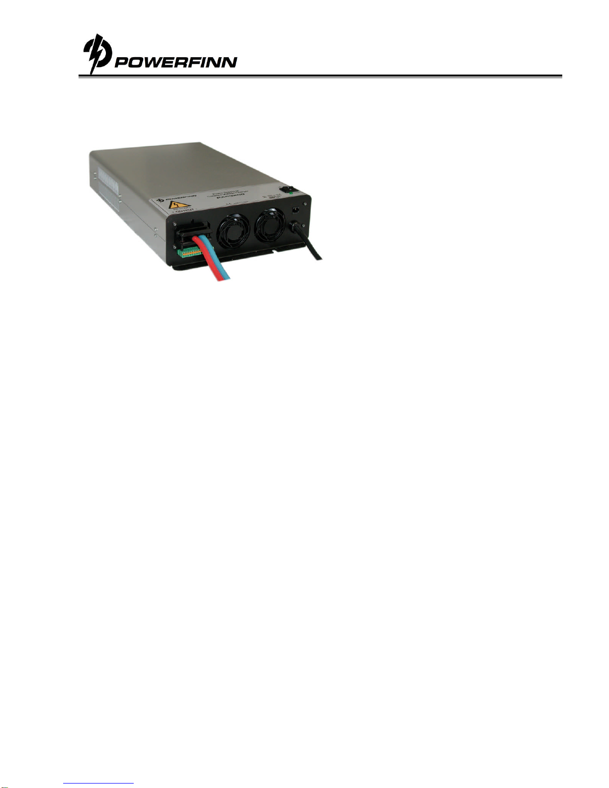
Switched Mode Power Supply
Operating manual PAP3200
Perämiehenkatu
6,
FIN
24100
Salo,
Tel.
+358
2
7
77
290,
Fax
+358
2
777
2918,
[email protected],
www.powerfinn.fi
4
Charging operation
1. Ensure that the power supply is switched off and that the environment meets the conditions as described in
the previous section.
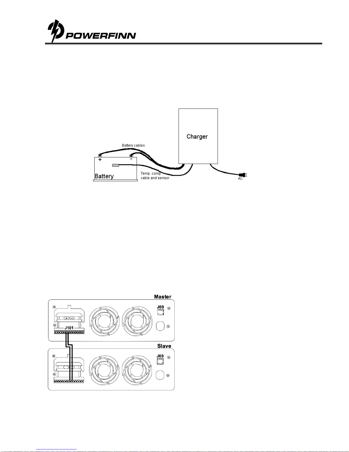
2. Connect the output cables to the load / battery terminals: + cable to the + terminal and – cable to the –
terminal
3. Turn the power on by turning the switch to position 1.
4. During normal power supply operation / charging process, the STATUS LED is continuously orange.
5. To avoid sparking, turn off the power supply before disconnecting the cables.
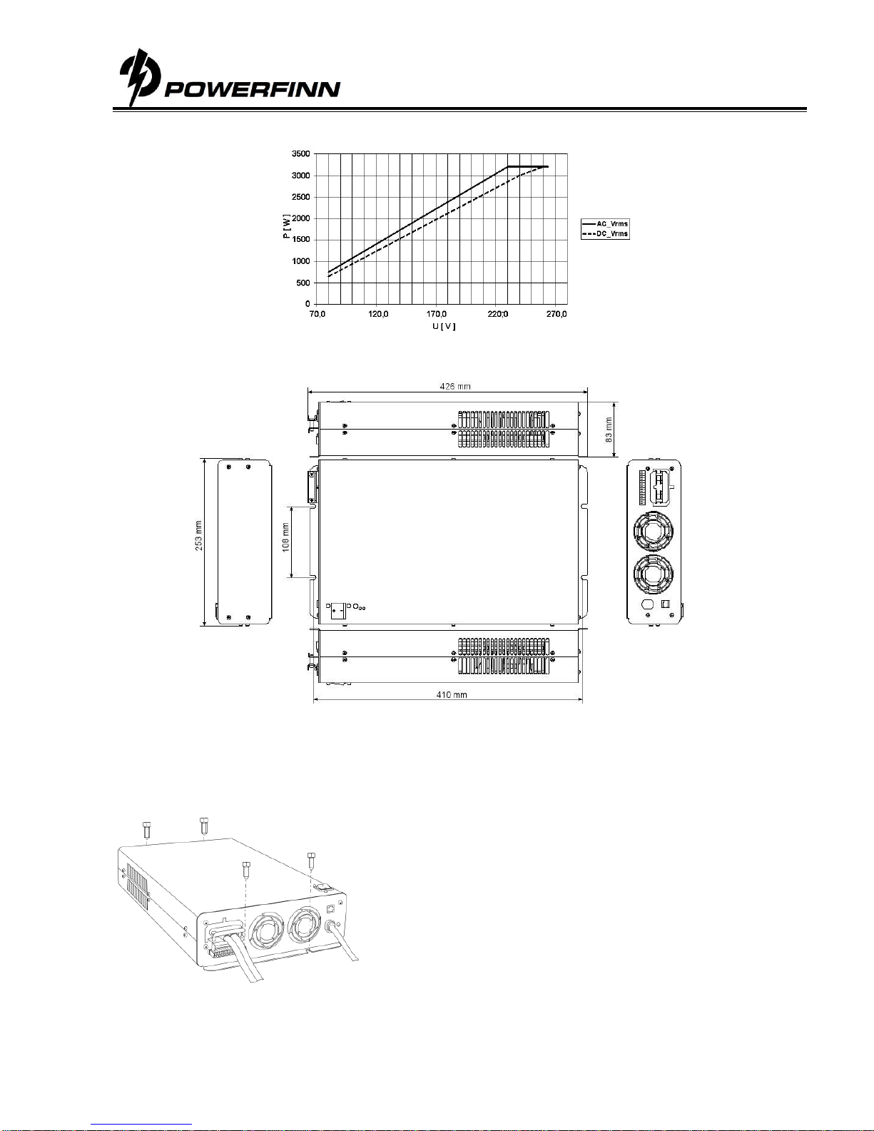
DC Input connection
The power supply input cable is connected as follows:
L negative or positive DC supply input
N positive or negative DC supply input
PE protective earth
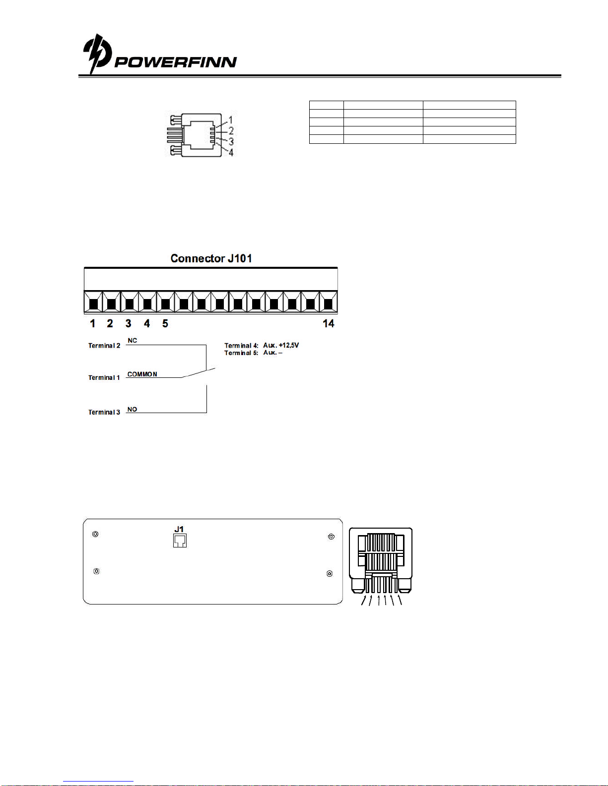
Output voltage and current limit adjustment
Trimmer or analog control adjustable modules, type example PAP3200/24 or PAP3200/24AI:
The output voltage and output current limit of the power supply can be adjusted as follows:
Trimmer adjustable models: with the multi-turn potentiometers accessible from the top cover.
Analog controllable models by an external 0-5Cdc voltage. See detailed description.
Both voltage and current can be adjusted from zero to the maximum value. Maximum 3200W / 3000W
output power is available within the adjustment range.
Temperature compensated models, type example PAP3200/24T:
The power supply includes 16 pre-programmed output voltages that are set by the code switch. See the
setting table for this unit. Any of these 16 different voltage settings can be taken in use and additionally be
adjusted within ±5% using the trimmer on the top cover. See the instructions for choosing the programmed
voltage and the fine-tune adjustment.
LED’s
STATUS LED indicates different phases during the charging process. In normal power supply operation an orange
led indicates a healthy output voltage.
Stand-by LED is ON when mains network (AC) is connected, but the power supply’s output is switched OFF by the
switch on top cover. Stand-by LED goes OFF when the power supply’s output is switched ON.
Over current protection
The output of the power supply is protected against over currents and short circuits by an automatic, self-resetting
electronic current limiter.
Series/parallel connection
Parallel operation: No restrictions, passive load sharing
Series operation: Up to 500V total voltage. For more information about use with an AI or S option, ask the
manufacturer.
Warning
Dangerous voltages, capable of causing death, are present in the power supply. Do not remove the cover. There
are no operator serviceable parts inside the unit. Refer servicing to qualified service personnel only.
This device is not meant to be used by children or people whose physical, sensory or mental attributes or lack of
experience and knowledge prevent them from using the device safely unless a person responsible for their safety
supervises them or has instructed them how to use the device.
It must be ensured that children do not play with the device.