Ubiquiti EdgePower EP-54V-150W User manual
25.02.2020 EP-54V-150W Quck Start Gude
https://dl.ubnt.com/qsg/EP-54V-150W/EP-54V-150W_EN.html 1/15
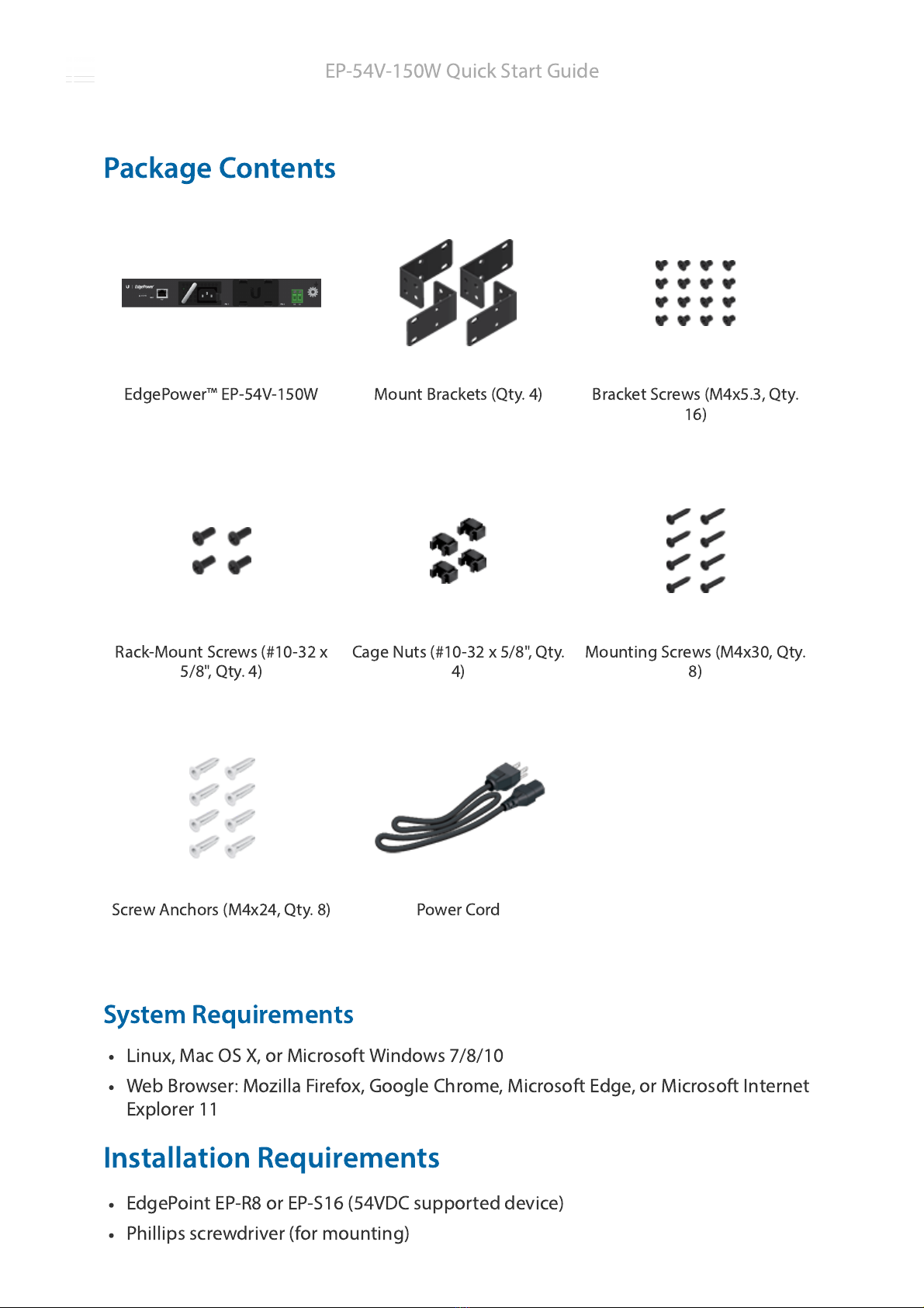
EdgePower™ EP-54V-150W Mount Brackets (Qty. 4) Bracket Screws (M4x5.3, Qty.
16)
Rack-Mount Screws (#10-32 x
5/8", Qty. 4) Cage Nuts (#10-32 x 5/8", Qty.
4) Mount
ng Screws (M4x30, Qty.
8)
Screw Anchors (M4x24, Qty. 8) Power Cord
Package Contents
System Requ
rements
L
nux, Mac OS X, or M
crosoft W
ndows 7/8/10
Web Browser: Moz
lla F
refox, Google Chrome, M
crosoft Edge, or M
crosoft Internet
Explorer 11
Installat
on Requ
rements
EdgePo
nt EP-R8 or EP-S16 (54VDC supported dev
ce)
Ph
ll
ps screwdr
ver (for mount
ng)
EP-54V-150W Qu
ck Start Gu
de
25.02.2020 EP-54V-150W Quck Start Gude
https://dl.ubnt.com/qsg/EP-54V-150W/EP-54V-150W_EN.html 2/15
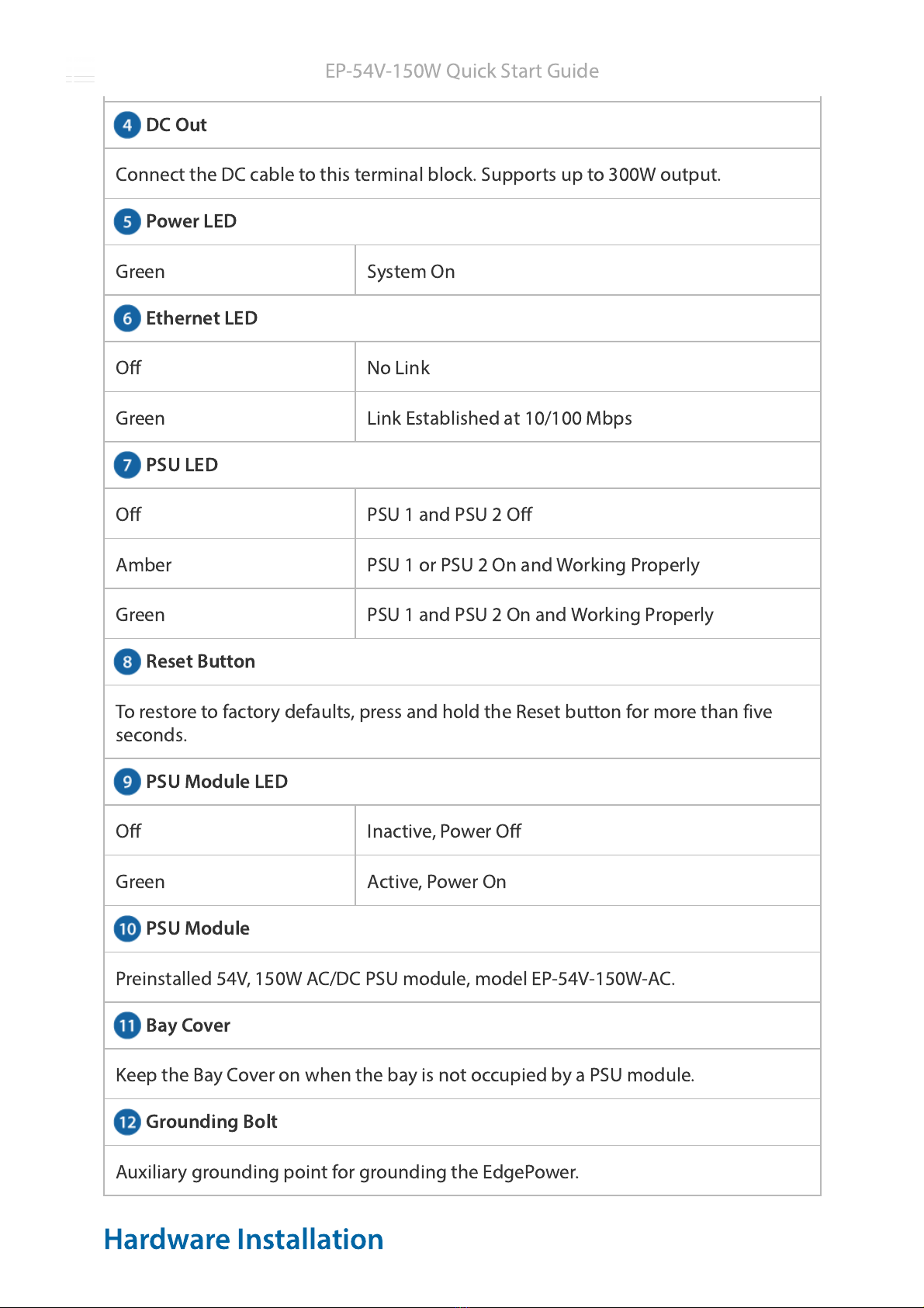
Management Port
PSU 1
PSU 2
Standard-s
zed, 19" w
de rack w
th a m
n
mum of 1U he
ght ava
lable (for rack-
mount
ng)
PowerCable™ or equ
valent outdoor-rated, 12 AWG stranded DC power cable
Note:
Although the cabl
ng can be located outdoors, the EdgePower
tself
should be housed
ns
de a protect
ve enclosure.
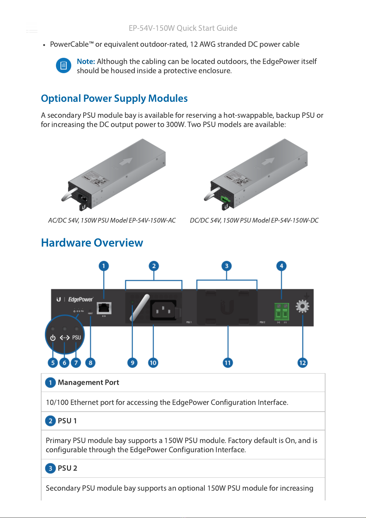
Opt
onal Power Supply Modules
A secondary PSU module bay
s ava
lable for reserv
ng a hot-swappable, backup PSU or
for
ncreas
ng the DC output power to 300W. Two PSU models are ava
lable:
AC/DC 54V, 150W PSU Model EP-54V-150W-AC DC/DC 54V, 150W PSU Model EP-54V-150W-DC
Hardware Overv
ew
10/100 Ethernet port for access
ng the EdgePower Conf
gurat
on Interface.
Pr
mary PSU module bay supports a 150W PSU module. Factory default
s On, and
s
conf
gurable through the EdgePower Conf
gurat
on Interface.
Secondary PSU module bay supports an opt
onal 150W PSU module for
ncreas
ng
EP-54V-150W Qu
ck Start Gu
de
25.02.2020 EP-54V-150W Quck Start Gude
https://dl.ubnt.com/qsg/EP-54V-150W/EP-54V-150W_EN.html 3/15
DC Out
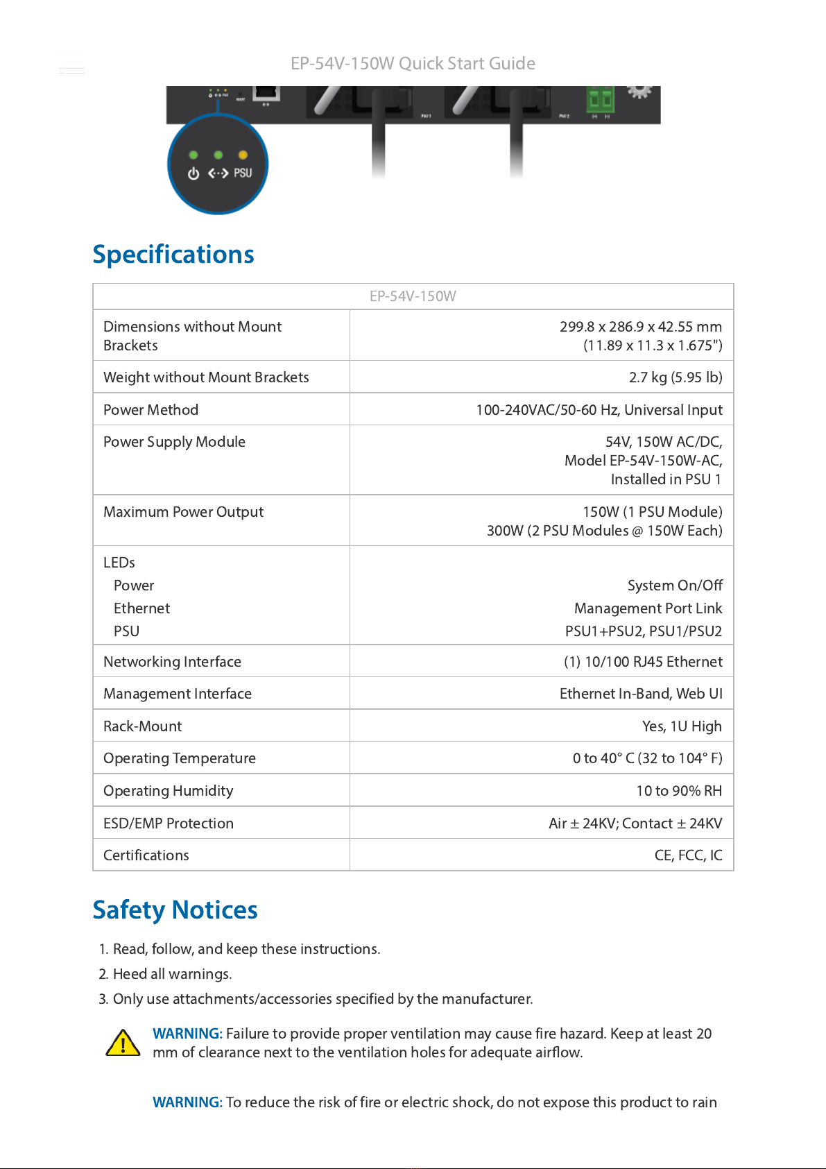
Power LED
Ethernet LED
PSU LED
Reset Button
PSU Module LED
PSU Module
Bay Cover
Ground
ng Bolt
power output, or conf
gured Off to house a spare PSU module. Factory default
s On,
and
s conf
gurable through the EdgePower Conf
gurat
on Interface.
Connect the DC cable to th
s term
nal block. Supports up to 300W output.
Green System On
Off No L
nk
Green L
nk Establ
shed at 10/100 Mbps
Off PSU 1 and PSU 2 Off
Amber PSU 1 or PSU 2 On and Work
ng Properly
Green PSU 1 and PSU 2 On and Work
ng Properly
To restore to factory defaults, press and hold the Reset button for more than f
ve
seconds.
Off Inact
ve, Power Off
Green Act
ve, Power On
Pre
nstalled 54V, 150W AC/DC PSU module, model EP-54V-150W-AC.
Keep the Bay Cover on when the bay
s not occup
ed by a PSU module.
Aux
l
ary ground
ng po
nt for ground
ng the EdgePower.
Hardware Installat
on
EP-54V-150W Qu
ck Start Gu
de
25.02.2020 EP-54V-150W Quck Start Gude
https://dl.ubnt.com/qsg/EP-54V-150W/EP-54V-150W_EN.html 4/15
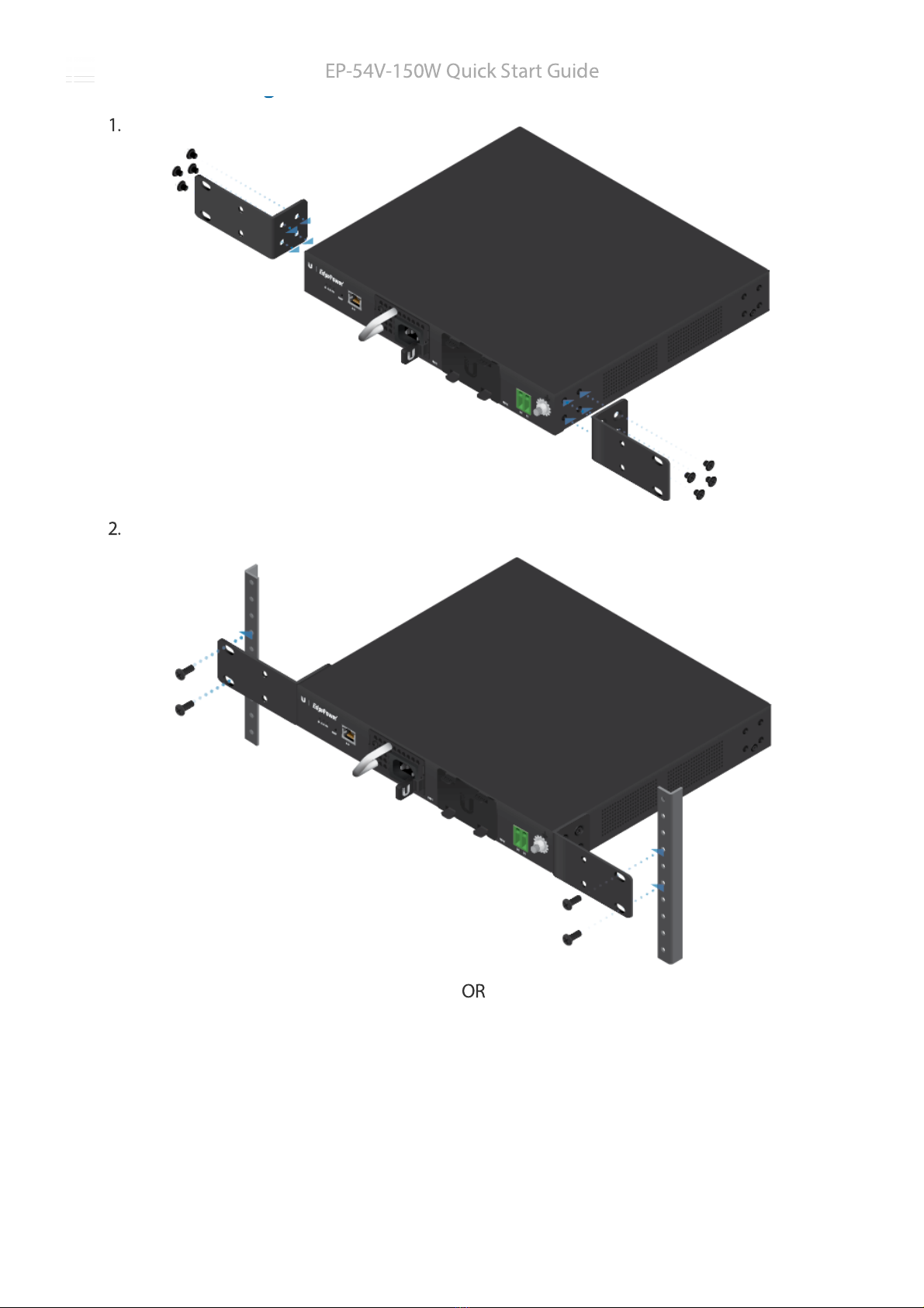
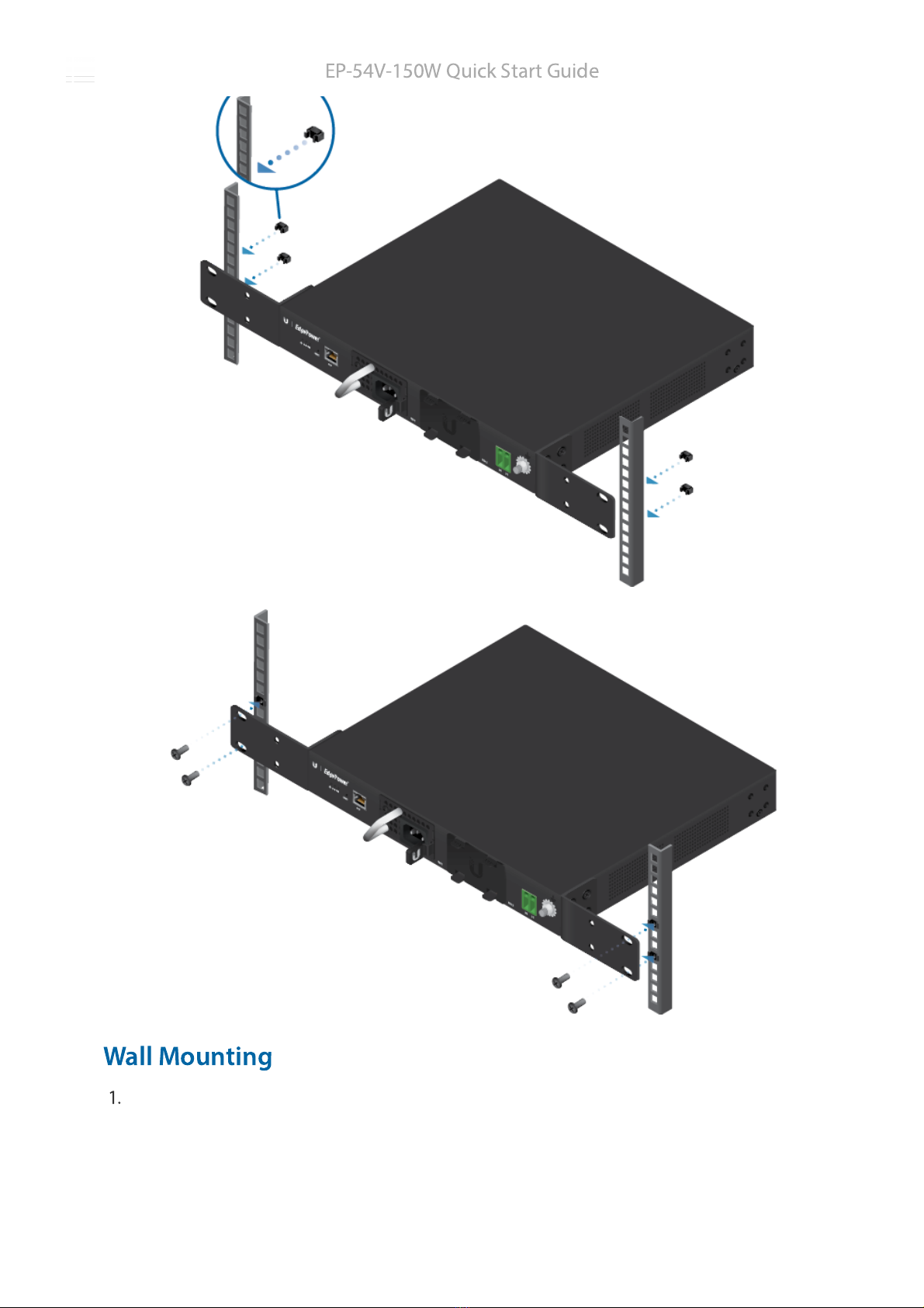
Rack Mount
ng
1.
2.
OR
EP-54V-150W Qu
ck Start Gu
de
25.02.2020 EP-54V-150W Quck Start Gude
https://dl.ubnt.com/qsg/EP-54V-150W/EP-54V-150W_EN.html 5/15
Wall Mount
ng
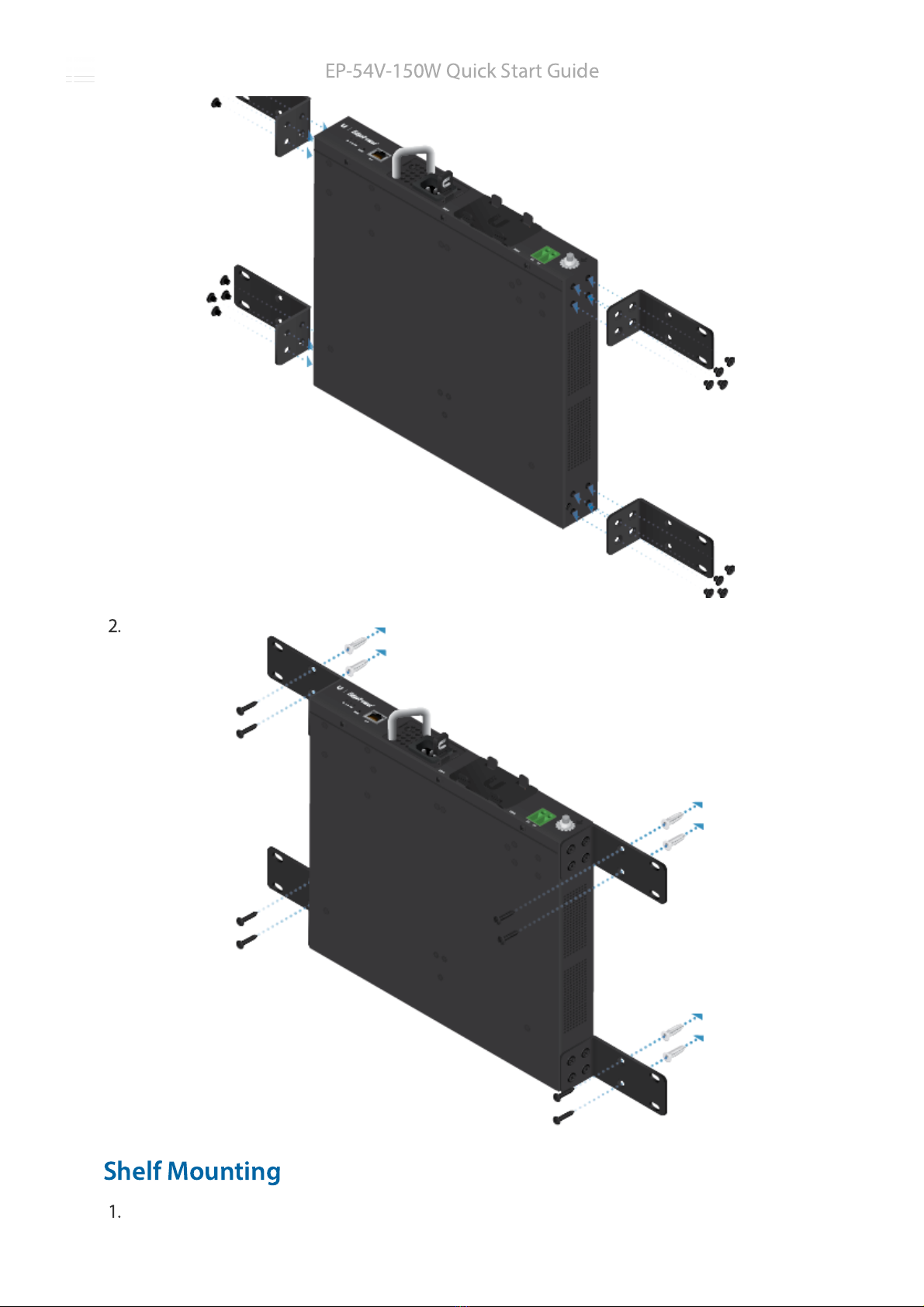
1.
EP-54V-150W Qu
ck Start Gu
de
25.02.2020 EP-54V-150W Quck Start Gude
https://dl.ubnt.com/qsg/EP-54V-150W/EP-54V-150W_EN.html 6/15
2.
Shelf Mount
ng
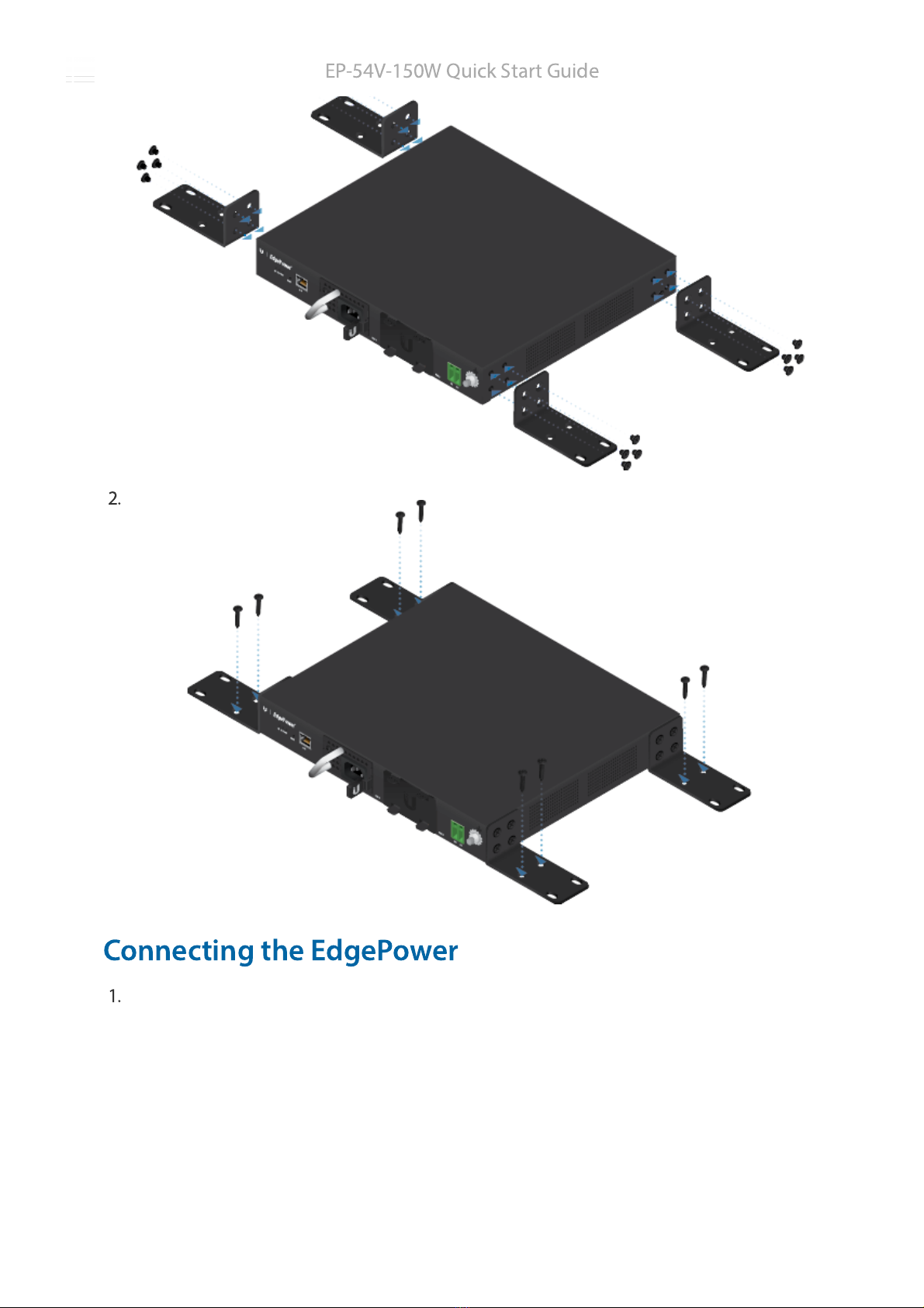
1.
EP-54V-150W Qu
ck Start Gu
de
25.02.2020 EP-54V-150W Quck Start Gude
https://dl.ubnt.com/qsg/EP-54V-150W/EP-54V-150W_EN.html 7/15
2.
Connect
ng the EdgePower
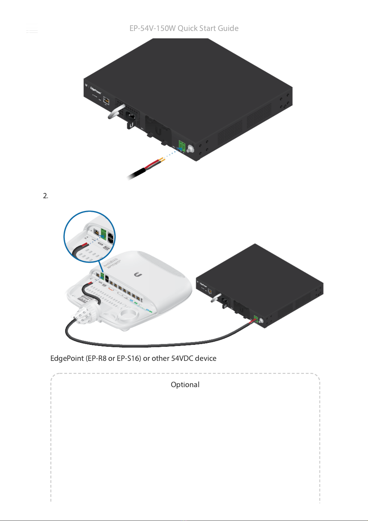
1.
EP-54V-150W Qu
ck Start Gu
de
25.02.2020 EP-54V-150W Quck Start Gude
https://dl.ubnt.com/qsg/EP-54V-150W/EP-54V-150W_EN.html 8/15
2.
EdgePo
nt (EP-R8 or EP-S16) or other 54VDC dev
ce
Opt
onal
EP-54V-150W Qu
ck Start Gu
de
25.02.2020 EP-54V-150W Quck Start Gude
https://dl.ubnt.com/qsg/EP-54V-150W/EP-54V-150W_EN.html 9/15
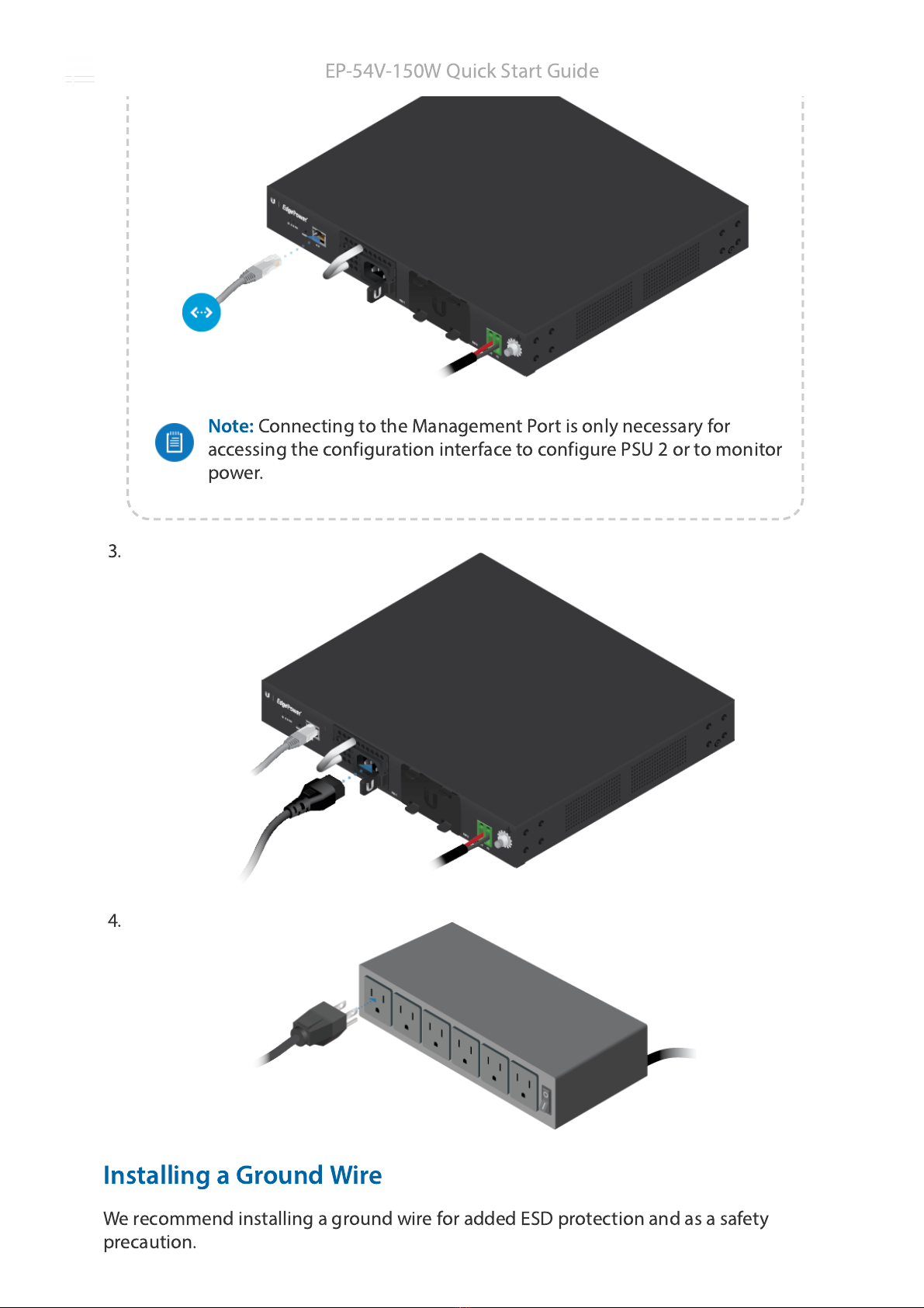
Note:
Connect
ng to the Management Port
s only necessary for
access
ng the conf
gurat
on
nterface to conf
gure PSU 2 or to mon
tor
power.
3.
4.
Install
ng a Ground W
re
We recommend
nstall
ng a ground w
re for added ESD protect
on and as a safety
precaut
on.
EP-54V-150W Qu
ck Start Gu
de
25.02.2020 EP-54V-150W Quck Start Gude
https://dl.ubnt.com/qsg/EP-54V-150W/EP-54V-150W_EN.html 10/15
Note:
For gu
del
nes about ground
ng and l
ghtn
ng protect
on, follow your
local electr
cal regulatory codes.
1.
2.
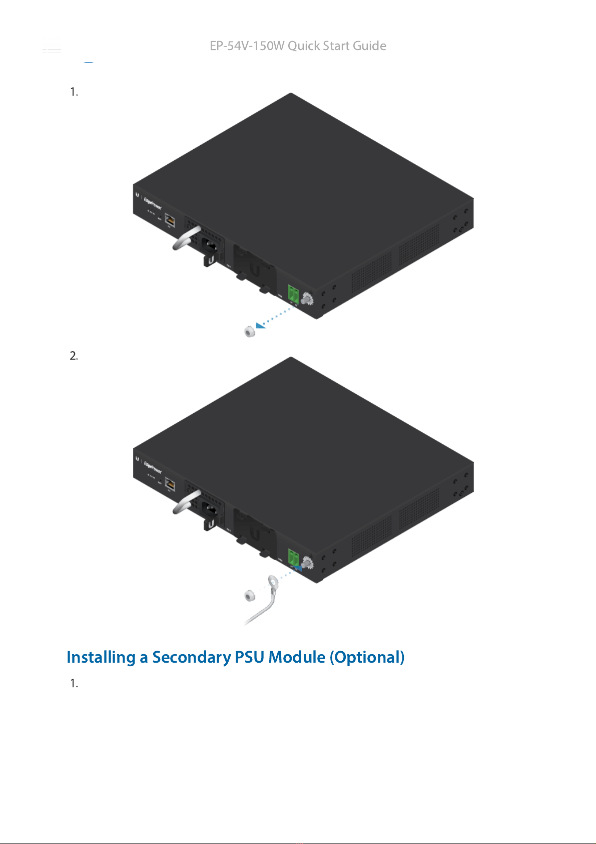
Install
ng a Secondary PSU Module (Opt
onal)
1.
EP-54V-150W Qu
ck Start Gu
de
25.02.2020 EP-54V-150W Quck Start Gude
https://dl.ubnt.com/qsg/EP-54V-150W/EP-54V-150W_EN.html 11/15
2.
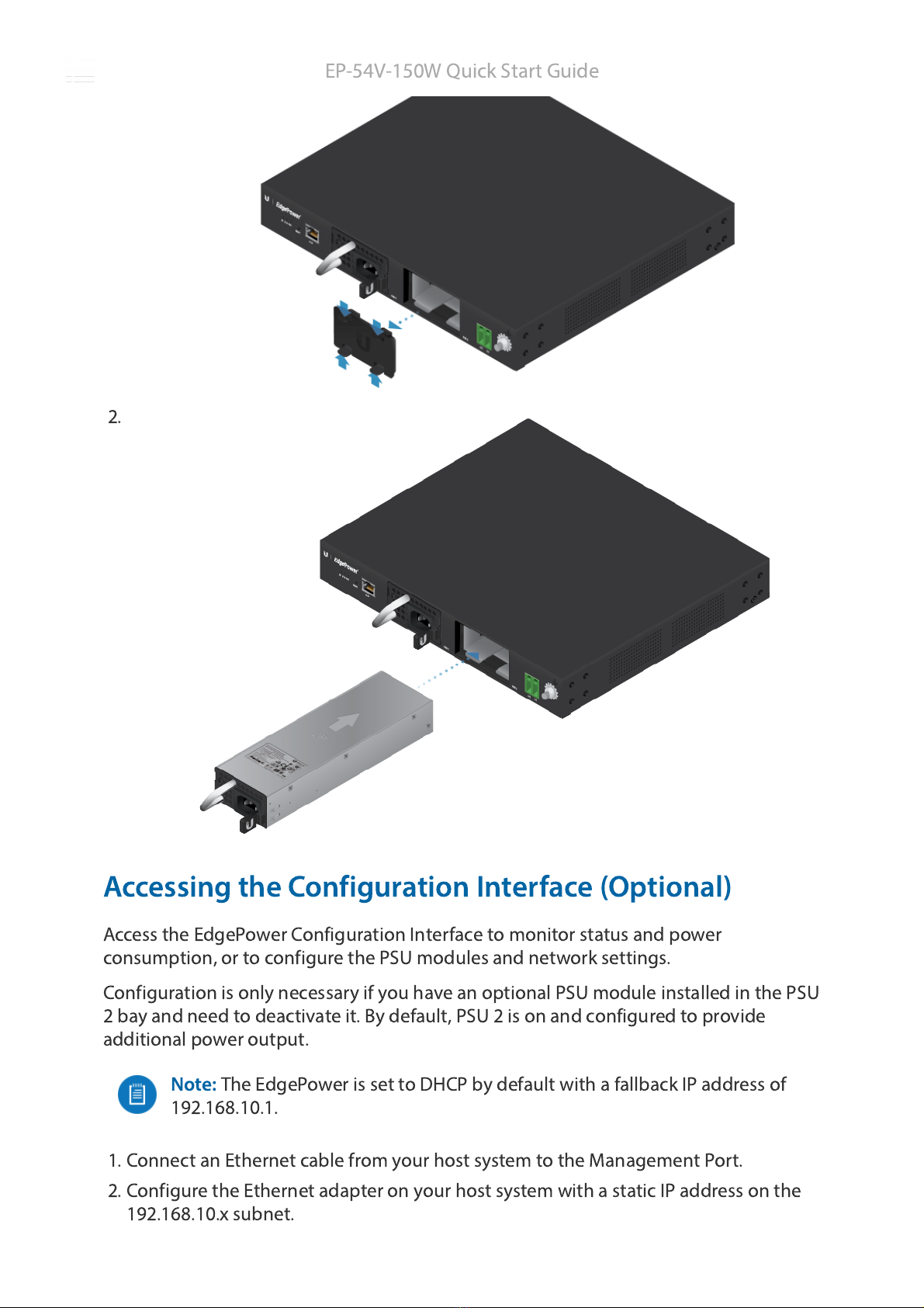
Access
ng the Conf
gurat
on Interface (Opt
onal)
Access the EdgePower Conf
gurat
on Interface to mon
tor status and power
consumpt
on, or to conf
gure the PSU modules and network sett
ngs.
Conf
gurat
on
s only necessary
f you have an opt
onal PSU module
nstalled
n the PSU
2 bay and need to deact
vate
t. By default, PSU 2
s on and conf
gured to prov
de
add
t
onal power output.
Note:
The EdgePower
s set to DHCP by default w
th a fallback IP address of
192.168.10.1.
1. Connect an Ethernet cable from your host system to the Management Port.
2. Conf
gure the Ethernet adapter on your host system w
th a stat
c IP address on the
192.168.10.x subnet.
EP-54V-150W Qu
ck Start Gu
de
25.02.2020 EP-54V-150W Quck Start Gude
https://dl.ubnt.com/qsg/EP-54V-150W/EP-54V-150W_EN.html 12/15
3. Launch your web browser. Type https://192.168.10.1
n the address f
eld. Press enter
(PC) or return (Mac).
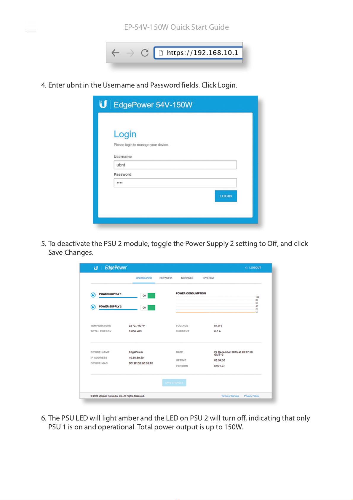
4. Enter ubnt
n the Username and Password f
elds. Cl
ck Log
n.
5. To deact
vate the PSU 2 module, toggle the Power Supply 2 sett
ng to Off, and cl
ck
Save Changes.
6. The PSU LED w
ll l
ght amber and the LED on PSU 2 w
ll turn off,
nd
cat
ng that only
PSU 1
s on and operat
onal. Total power output
s up to 150W.
EP-54V-150W Qu
ck Start Gu
de
25.02.2020 EP-54V-150W Quck Start Gude
https://dl.ubnt.com/qsg/EP-54V-150W/EP-54V-150W_EN.html 13/15
Spec
f
cat
ons
EP-54V-150W
D
mens
ons w
thout Mount
Brackets 299.8 x 286.9 x 42.55 mm
(11.89 x 11.3 x 1.675")
We
ght w
thout Mount Brackets 2.7 kg (5.95 lb)
Power Method 100-240VAC/50-60 Hz, Un
versal Input
Power Supply Module 54V, 150W AC/DC,
Model EP-54V-150W-AC,
Installed
n PSU 1
Max
mum Power Output 150W (1 PSU Module)
300W (2 PSU Modules @ 150W Each)
LEDs
Power System On/Off
Ethernet Management Port L
nk
PSU PSU1+PSU2, PSU1/PSU2
Network
ng Interface (1) 10/100 RJ45 Ethernet
Management Interface Ethernet In-Band, Web UI
Rack-Mount Yes, 1U H
gh
Operat
ng Temperature 0 to 40° C (32 to 104° F)
Operat
ng Hum
d
ty 10 to 90% RH
ESD/EMP Protect
on A
r ± 24KV; Contact ± 24KV
Cert
f
cat
ons CE, FCC, IC
Safety Not
ces
1. Read, follow, and keep these
nstruct
ons.
2. Heed all warn
ngs.
3. Only use attachments/accessor
es spec
f
ed by the manufacturer.
WARNING:
Fa
lure to prov
de proper vent
lat
on may cause f
re hazard. Keep at least 20
mm of clearance next to the vent
lat
on holes for adequate a
row.
WARNING:
To reduce the r
sk of f
re or electr
c shock, do not expose th
s product to ra
n
EP-54V-150W Qu
ck Start Gu
de
25.02.2020 EP-54V-150W Quck Start Gude
https://dl.ubnt.com/qsg/EP-54V-150W/EP-54V-150W_EN.html 14/15
or mo
sture.
WARNING:
Do not use th
s product
n locat
on that can be submerged by water.
WARNING:
Avo
d us
ng th
s product dur
ng an electr
cal storm. There may be a remote
r
sk of electr
c shock from l
ghtn
ng.
Electr
cal Safety Informat
on
1. Compl
ance
s requ
red w
th respect to voltage, frequency, and current requ
rements
nd
cated
on the manufacturer’s label. Connect
on to a d
fferent power source than those spec
f
ed may
result
n
mproper operat
on, damage to the equ
pment or pose a f
re hazard
f the l
m
tat
ons
are not followed.
2. There are no operator serv
ceable parts
ns
de th
s equ
pment. Serv
ce should be prov
ded only
by a qual
f
ed serv
ce techn
c
an.
3. Th
s equ
pment
s prov
ded w
th a detachable power cord wh
ch has an
ntegral safety ground
w
re
ntended for connect
on to a grounded safety outlet.
a. Do not subst
tute the power cord w
th one that
s not the prov
ded approved type. Never
use an adapter plug to connect to a 2-w
re outlet as th
s w
ll defeat the cont
nu
ty of the
ground
ng w
re.
b. The equ
pment requ
res the use of the ground w
re as a part of the safety cert
f
cat
on,
mod
f
cat
on or m
suse can prov
de a shock hazard that can result
n ser
ous
njury or death.
c. Contact a qual
f
ed electr
c
an or the manufacturer
f there are quest
ons about the
nstallat
on pr
or to connect
ng the equ
pment.
d. Protect
ve earth
ng
s prov
ded by L
sted AC adapter. Bu
ld
ng
nstallat
on shall prov
de
appropr
ate short-c
rcu
t backup protect
on.
e. Protect
ve bond
ng must be
nstalled
n accordance w
th local nat
onal w
r
ng rules and
regulat
ons.
L
m
ted Warranty
u
.com/support/warranty
The l
m
ted warranty requ
res the use of arb
trat
on to resolve d
sputes on an
nd
v
dual bas
s, and,
where appl
cable, spec
fy arb
trat
on
nstead of jury tr
als or class act
ons.
Compl
ance
FCC
Changes or mod
f
cat
ons not expressly approved by the party respons
ble for compl
ance could
vo
d the user’s author
ty to operate the equ
pment.
Th
s dev
ce compl
es w
th Part 15 of the FCC Rules. Operat
on
s subject to the follow
ng two
cond
t
ons.
1. Th
s dev
ce may not cause harmful
nterference, and
2. Th
s dev
ce must accept any
nterference rece
ved,
nclud
ng
nterference that may cause
undes
red operat
on.
EP-54V-150W Qu
ck Start Gu
de
25.02.2020 EP-54V-150W Quck Start Gude
https://dl.ubnt.com/qsg/EP-54V-150W/EP-54V-150W_EN.html 15/15
Th
s equ
pment has been tested and found to comply w
th the l
m
ts for a Class A d
g
tal dev
ce,
pursuant to Part 15 of the FCC Rules. These l
m
ts are des
gned to prov
de reasonable protect
on
aga
nst harmful
nterference when the equ
pment
s operated
n a commerc
al env
ronment. Th
s
equ
pment generates, uses, and can rad
ate rad
o frequency energy and,
f not
nstalled and used
n accordance w
th the
nstruct
on manual, may cause harmful
nterference to rad
o
commun
cat
ons. Operat
ons of th
s equ
pment
n a res
dent
al area
s l
kely to cause harmful
nterference
n wh
ch case the user w
ll be requ
red to correct the
nterference at h
s own expense.
ISED Canada
CAN ICES-3(A)/NMB-3(A)
Austral
a and New Zealand
Warn
ng: Th
s equ
pment
s compl
ant w
th Class A of CISPR 32. In a res
dent
al
env
ronment th
s equ
pment may cause rad
o
nterference.
CE Mark
ng
CE mark
ng on th
s product represents the product
s
n compl
ance w
th all d
rect
ves that are
appl
cable to
t.
WEEE Compl
ance Statement
Declarat
on of Conform
ty
Onl
ne Resources
© 2020 Ub
qu
t
Inc. All r
ghts reserved.
EP-54V-150W Qu
ck Start Gu
de
Other manuals for EdgePower EP-54V-150W
1
Other Ubiquiti Power Supply manuals

Ubiquiti
Ubiquiti EdgePower EP-54V-72W User manual

Ubiquiti
Ubiquiti EdgePower EP-24V-72W User manual

Ubiquiti
Ubiquiti UniFi SmartPower USP-RPS User manual

Ubiquiti
Ubiquiti EdgePower 54V User manual

Ubiquiti
Ubiquiti EdgePower EP-54V-150W User manual

Ubiquiti
Ubiquiti USP-RPS User manual

Ubiquiti
Ubiquiti USP-RPS User manual
Popular Power Supply manuals by other brands

Videx
Videx 520MR Installation instruction

Poppstar
Poppstar 1008821 Instructions for use

TDK-Lambda
TDK-Lambda LZS-A1000-3 Installation, operation and maintenance manual

TDK-Lambda
TDK-Lambda 500A instruction manual

Calira
Calira EVS 17/07-DS/IU operating instructions

Monacor
Monacor PS-12CCD instruction manual


