Messtechnik optoUSB-3.0 User manual

Manual
optoUSB-3.0
Digital optical transmitter
for USB signals
Distributed by: Reliant EMC LLC, 3311 Lewis Ave, Signal Hill CA 90755, 4089165750, www.reliantemc.com

Date
20.02.19 optoUSB-3.0
Page: 2 Manual
Table of contents
1 Disclaimer of Warrant /Exclusion of Liabilit ............................................................................................................3
2 Special Regulations and Notes...................................................................................................................................3
2.1 Safet .................................................................................................................................................................3
2.2 Product Care and Maintenance.........................................................................................................................3
2.3 Cleaning.............................................................................................................................................................3
2.4 Installation Instructions.....................................................................................................................................4
3 Regulations and References.......................................................................................................................................4
3.1 Properties..........................................................................................................................................................4
3.2 Regulations and References..............................................................................................................................5
3.3 Charging the Batteries (Batter Pack or Integrated into the Device)................................................................6
4 Characteristics and field of application.....................................................................................................................7
5 Box contents..............................................................................................................................................................8
6 Housing and connectors / switches...........................................................................................................................9
7 Operation and handling of the optoUSB3.0............................................................................................................11
8 Maintenance............................................................................................................................................................12
9 Trouble shooting......................................................................................................................................................13
10 Accessories / Options............................................................................................................................................14
11 Contact...................................................................................................................................................................14
Distributed by: Reliant EMC LLC, 3311 Lewis Ave, Signal Hill CA 90755, 4089165750, www.reliantemc.com

optoUSB-3.0 Date
20.02.19
Manual Page 3
1 Disclaimer of Warranty/Exclusion of Liability
§Under the Following Circumstances the Warranty and Liability is Excluded
•Usage not according to the intended purpose and misapplication
•Non-observance of the safet instructions
•Manipulation and modification of the devices
2 Special Regulations and Notes
The following regulations have to be respected for all devices. Additionall , all the specific notes for each device
have to be respected (see the following chapters).
2.1 Safety
Interferences, that are not described in chapter 13, and an damage of the devices (e.g. damaged housing or
damaged cables at the charger) have to be reported to the responsible expert immediatel .
The affected device has to be decommissioned b the responsible expert and must be protected against incorrect
usage until all damages have been repaired.
2.2 Product Care and Maintenance
•Batter packs of the devices have to be maintained on a regular basis (see chapter 9).
•Charging of the batter packs has to be done according to the instructions described in chapter 9.
•Other components of the devices are maintenance free.
•Repairs must onl be done b the manufacturer.
§
Risk of Fire, Injury, and Damage to the Electronics
There are no user-serviceable maintainable parts in the devices. Opening the devices can lead
to short circuits if powered components touch the housing of the device. Therefore NEVER
open the housings, because there is a risk of fire or injur !
In case of errors consider the notes in chapter 10. If an error cannot be solved b considering
these notes, please send the device in for repair. In this case, please contact BEFORE ou send
in the device.
2.3 Cleaning
•Cleaning of the housings onl with solvent-free cleaning supplies and a soft cloth.
•Do not use aggressive cleaning supplies like alcohol, acetone, or abrasive materials.
Distributed by: Reliant EMC LLC, 3311 Lewis Ave, Signal Hill CA 90755, 4089165750, www.reliantemc.com

Date
20.02.19 optoUSB-3.0
Page: 4 Manual
2.4 Installation Instructions
!
Risk of Fire or Damage
Do not open the devices. Opening the devices is onl allowed with the necessar guidance and
previous authorization from . Non-observance can lead to fire or damage of the device.
Warrant will be void!
§
Possible Risk of Injury and Damage When not Observing this Manual.
The devices described in this manual, especiall the pan/tilt unit, are ver complex. This
manual must be read and respected compellingl before installation and initial operation.
Safet instructions must be respected compellingl .
Disregard can lead to considerable damage of the devices and serious risk of injur for the
user.
•Use the devices onl on skid-proof surfaces, respect the specific installation references for each device.
•Electrical connections are onl allowed to be done b authorized EMC trained specialist staff.
•Consider electrical parameters and correct pinning assignment.
•Incorrect electrical connections can damage the components of the devices.
•Expert onl installation of the connections, provide a strain relief if necessar .
•Do not mechanicall work on devices and cases!
•Do not modif or short circuit plugs and do not shorten or extend included cables without the approval b the
manufacturer!
3 Regulations and References
3.1 Properties
Batteries are either integrated into the devices from or delivered separatel as external batter packs.
The number of cells varies and depends on the respective needed required voltages.
The related charger has the following properties:
•Power suppl with power plug (Standard EU (T pe C or F) unless ordered otherwise, optional US (t pe A), UK
(t pe G), AU (t pe I))
•Integrated LEDs to displa the charging level of the connected devices respectivel the connected batter packs.
•Short-circuit-proof, reverse polarit protected
•Suitable for batteries with 4 … 10 cells and a capacit of 1.,0 … 10.,0 Ah
•Charging process IUoU
Chargers with the charging process IUoU work basicall identical to those using the IU (CCCV) charging process.
After reaching the end of charging voltage however, the device switches to trickle charging. This wa , a self-
Distributed by: Reliant EMC LLC, 3311 Lewis Ave, Signal Hill CA 90755, 4089165750, www.reliantemc.com

optoUSB-3.0 Date
20.02.19
Manual Page 5
discharge is avoided.
3.2 Regulations and References
Protect the batteries from heat (e.g. long times of exposure to direct sunlight) and fire. Do not immerse the
batteries into fluids. Otherwise there is a risk of explosions.
§Risk of Damage and Explosion Because of Incorrect Treatment
Unintentional or incorrect treatment can damage the batteries, which can even lead to
explosions of the batteries!
Batteries that are integrated into the devices of or are delivered with them, ma onl be charged with the
intended chargers from .
These components are compatible to each other, other chargers ma damage the s stem or ma reduce the
capacit or life span of the batteries significantl .
Respect the following references when operating the chargers:
•Use chargers only for charging devices and batteries.
•Switch devices off before connecting the charger.
•Do NOT switch on the device during the charging process.
•Maximum charging current 1 A.
•Disconnect charger before turning on the device on.
•Prior to the first use, charge the batteries completel .
•Charge the batteries before use if ou have not used them for a longer period (self discharge of the NiMH
batteries) and after use.
•To avoid capacit loss due to the memor effect, discharge the batteries completel ever 5 charging c cles. To
do this, leave the device on, until it turns off b itself. Then start the charging process as described above.
§Risk Through High Voltage at the Charging Device
•The charger works with mains voltage.
•Securit references for work with mains voltage must be followed.
!
Warning of Reduced Capacity and Life Span of the Batteries due to Maloperation
Use onl the intended chargers from .
Powered devices must never be used with a connected charger, e.g. for buffering an empt
batter .
Disregard can lead to a loss of capacit and a shortened life span of the batter in a short time.
3.3 Charging the Batteries (Battery Pack or Integrated into the Device)
Start of the Charging Process
Distributed by: Reliant EMC LLC, 3311 Lewis Ave, Signal Hill CA 90755, 4089165750, www.reliantemc.com

Date
20.02.19 optoUSB-3.0
Page: 6 Manual
•Place the batter pack or the device to charge onto a stable and skid proof surface.
•Turn off the device off (see appropriate chapter for operation and operating controls).
•Connect the charger with the batter pack or the device using the designated screw connector (see appropriate
chapter for operating elements).
•Plug the power cord of the charger into the power socket.
•Do not power on the device during charging, this can damage the device.
•Check the status of the charging LED periodicall (the meaning of the states are printed onto the housing of the
charger).
End of the Charging Process, After the Charging LED Displays the Status “Full”
•Make sure that the device to charge is still turned off.
•Remove the connection between the charger and the screw connectors of the batter pack or the device to
charge.
•Remove the power plug of the charger from the socket.
•The device or batter pack is now read for operation.
Distributed by: Reliant EMC LLC, 3311 Lewis Ave, Signal Hill CA 90755, 4089165750, www.reliantemc.com

optoUSB-3.0 Date
20.02.19
Manual Page 7
4 Environmentally Friendly Disposal
4.1 Disposal of Devices
All devices must be disposed according to the environmental regulations in force.
Important Notice For Disposal of Devices
•Used equipment must be collected separatel and disposed in an environmentall friendl
manner.
•Electrical and electronic devices must NEVER be disposed of in the household waste.
•You can return old electrical and electronic devices to at no cost.
4.2 Disposal of Batteries
Due to their natural capacit loss, batteries must be replaced after their lifespan.
NEVER open devices or housings b ourself. Replacement of batteries must be done b . Please contact for
further details.
Important Notice For the Disposal of Batteries
•Disposing of batteries in the household waste is prohibited b law!
•Batter packs and devices containing batteries or environmental pollutants are marked b a
s mbol showing a crossed out garbage container (see picture on the left).
Distributed by: Reliant EMC LLC, 3311 Lewis Ave, Signal Hill CA 90755, 4089165750, www.reliantemc.com

Date
20.02.19 optoUSB-3.0
Page: 8 Manual
5 Characteristics and field of application
The digital optical s stem optoUSB-3.0 can be used to opticall transmit USB signals with a data rate of up to
5 Gbit/s correlating to USB3.0 standard. Because of the optical transmission, the s stem is ver robust against EMS
(electromagnetic susceptibilit ). It can withstand high electric and magnetic fields, like the appear in EMC tests.
The s stem also is optimized for low noise emission.
Please note that the USB-3.0 is NOT downwards compatible. I.e. there is no transmission with USB2.0 devices.
For the HUB side transceiver, power is supplied b internal NiMH batteries which make the s stem eas to use.
The optoUSB-3.0 is prepared for the use of external batteries (with the optional batter pack BP84).
For the PC side transceiver, power is supplied via the USB cable connected to a PC.
6 Box contents
Quantity Description
2 Transceivers optoUSB-3.0 (PC side and HUB side)
1 Duplex multimode optical fiber 62.5 / 125µm
1 Charger (standard)
1 USB 3.0 cable
1 Manual (English)
External batter packs BP84 (optional)
Shielded suppl cable for batter packs (optional)
The shipment includes charged batteries. However, due to the self-discharging of NiMH-batteries, the should be
recharged again before use.
Read chapter 9(Maintenance) before charging the devices!
iRead chapter 9 before charging!
The battery lasts 2-10h. Main factor is the power consumption of the connected
load.
The operating time can be extended by external, shielded battery packs.
Distributed by: Reliant EMC LLC, 3311 Lewis Ave, Signal Hill CA 90755, 4089165750, www.reliantemc.com

optoUSB-3.0 Date
20.02.19
Manual Page 9
7 Housing and connectors / pushbuttons
Fig. 7.1 shows the front side of the transceivers with connectors and push buttons:
•transceiver HUB side onl : power push button with control LED (Pwr On/Off)
•transceiver HUB side onl : batter information LED (Info)
•transceiver HUB side onl : charge plug (Charge)
•optical connector FSMA (Optical I/O) for duplex multimode fiber (62.5/125µm)
Fig. 7.1: Front side of the USB3. transceivers – HUB side on the left, PC side on the right
Distributed by: Reliant EMC LLC, 3311 Lewis Ave, Signal Hill CA 90755, 4089165750, www.reliantemc.com
Date
20.02.19 optoUSB-3.0
Page: 10 Manual
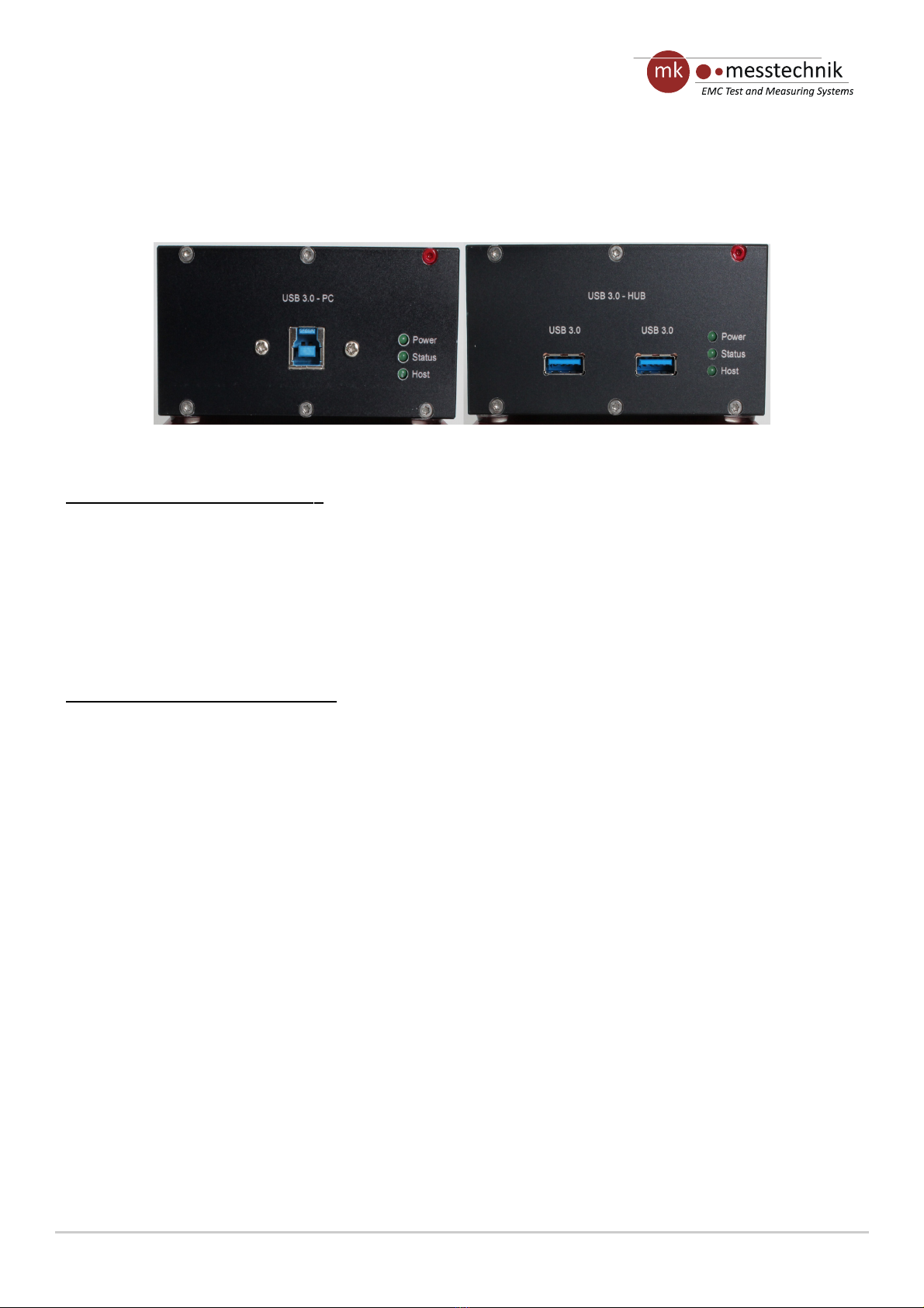
Fig. 7.2 shows the rear side of the transceiver (PC side, left) and the transceiver (Hub side, right) with connectors
and control LEDs.
Description of transceiver 1 ( PC side
):
•USB3.0 t pe B connector to connect the PC side transceiver with a USB 3.0 cable to a PC.
•Control LED Power is on when the transceiver is turned on.
•Control LED Status is on, when the two transceivers are connected. If the Status LED is blinking, the
transceiver is waiting for the connection to the other transceiver.
•Control LED Host indicates an active connection to a PC.
•
Description of transceiver 2 ( HUB side
):
•2x USB3.0 t pe A connector to connect USB3.0 devices
•Control LED Power is on when the transceiver is turned on.
•Control LED Status is on, when the two transceivers are connected. If the Status LED is blinking, the
transceiver is waiting for the connection to the other transceiver.
•Control LED Host indicates an active connection to a PC.
The housing of the USB connectors is connected to the aluminum case, which is connected to the circuit GND.
This should be taken into account during the test (possible ground loops, short circuits, parasitics to GND-plane!).
Fig. 7.2: Rear side of the devices – PC side on the left, HUB side on the right
Distributed by: Reliant EMC LLC, 3311 Lewis Ave, Signal Hill CA 90755, 4089165750, www.reliantemc.com

optoUSB-3.0 Date
20.02.19
Manual Page 11
8 Operation and handling of the optoUSB3.0
•Connect the optical fiber (Out => In, In => Out). Use 62.5/125µm multimode fibers onl , which are part of
the scope of deliver .
•Turn on the transceiver with the integrated USB hub connectors (HUB side).
•Connect our USB device with one of the two USB3.0 t pe A ports of the transceiver HUB side. Please
note: If ou use this side inside the anechoic chamber, the USB cable should be as short as possible and of
high qualit (rf shielding) to avoid rf coupling.
•Connect the transceiver PC side to a PC with the USB3.0 cable. Please wait until the operating s stem has
detected and added the device. If applicable, drivers ma have to be installed for the USB3.0 host
controller. Usuall , the drivers are installed automaticall b the operating s stem.
•The transmission starts automaticall after a short initialization.
If the transmission suddenl stops after a long duration of measurement, check the Info LED of the transceiver
(see Fig. 7.1).
The transceiver PC side does not have integrated batteries but is powered b a PC when connected with the
USB3.0 cable.
The transceiver HUB side is powered b an integrated 7 cell pack that has a nominal voltage of 8,4V. If the batter
power falls below 7,5V, the Info LED is switched on. The s stem should be reloaded soon. Below 6V, the s stem
turns off automaticall .
iThe maximal charging current is 1A.
The measurements can be extended b using the optional batter pack BP84 or an optional shielded power suppl
certified b mk-messtechnik. The external suppl can be connected to the s stem an time (parallel). The
connection to the internal batter is decoupled with a diode.
Distributed by: Reliant EMC LLC, 3311 Lewis Ave, Signal Hill CA 90755, 4089165750, www.reliantemc.com

Date
20.02.19 optoUSB-3.0
Page: 12 Manual
Onl use the batter pack and connector cables from mk-messtechnik! Others might lead to a damage of the
s stem!
!
The USB cable should be as short as possible and of high quality (rf shielding) to
avoid rf coupling.
Use cables approved by mk-messtechnik only! Disregard can lead to damages to the
devices.
Do not open the devices! Risk of short circuit, fire, and injuries!
The included chargers are not meant to power the transceivers during operation. The transceiver outside the
shielded room can be run with an external power suppl (optional). The internal transceiver can be run with an
external batter , if needed (optional). Do not use the external power suppl or charger to power the transceiver
inside the shielded room while EMI-tests are running. This might damage the transceiver!
Due to self-discharge issues with NiMH batteries, recharge batteries before use, if the s stem has not been used
for a longer time.
9 Maintenance
Recharge batteries after use with the enclosed charger. To prevent a laz batter effect, discharge the devices
ever 5 times completel b using the automatic switch off (Leave the s stem on, until it turns off automaticall ).
Afterwards, charge the devices as usual.
The devices have to be turned off before connecting to the charger. If this is disregarded, the s stem might get
damaged!
2 shows the pinning of the charge connector. Chargers have to be connected to pin 2 (+) and pin 4 (GND). An
external suppl (9V, 1A) can be connected to pin 3 (+) and pin 4 (GND). Use only power supplies which are
certified by mk-messtechnik.
Do not open the devices, as there are no parts inside which have to be maintained. The opened housing can pose
a fire hazard through short-circuit currents! Please contact our distributor or the manufacturer if ou have an
problems. Send in the complete s stem (both transceivers), if a problem cannot be solved b turning the devices
off and on again or b checking the positions of the switches. Please contact us in an case before sending in the
Fig. 2: Pinning of charge- / buffer connector
Distributed by: Reliant EMC LLC, 3311 Lewis Ave, Signal Hill CA 90755, 4089165750, www.reliantemc.com

optoUSB-3.0 Date
20.02.19
Manual Page 13
devices.
Distributed by: Reliant EMC LLC, 3311 Lewis Ave, Signal Hill CA 90755, 4089165750, www.reliantemc.com

Date
20.02.19 optoUSB-3.0
Page: 14 Manual
10 Trouble shooting
The following trouble shooting list is provided to assist ou while having problems. It might let ou use the s stem
again without a long down time:
Error Possible reasons Solution
No or erroneous transmission Receiver does not receive an optical
signal
Cables damaged or not
attached properl
Wrong optical fibers
(diameter)
Low batter
S stem turned off
Check optical fibers and connections,
change
fibers if necessar
Connectors and cables
regarding damages
Use fiber with
62,5/125µm
Charge batteries
Turn on all devices
Transmission stops Low batter
No optical signal at receiver
S stem turned off
Charge batteries
Check for light at optical output.
Replace optical
fiber
Turn on all devices
Device cannot be turned on, cannot
be charged
Batteries damaged
Internal fuse is broke
Charger or cable
damaged
Batteries
over discharged
Send device to us
Send device to us
Check / replace charger
and charging cable
Charge batteries, ma be use other
charger (5 batter cells)
Common problems Defective optical or electrical cables
or connectors
Check connectors, fibers and cables.
Test with other ones.
Replace cables
Distributed by: Reliant EMC LLC, 3311 Lewis Ave, Signal Hill CA 90755, 4089165750, www.reliantemc.com

optoUSB-3.0 Date
20.02.19
Manual Page 15
11 Accessories / Options
Part Order number Comment
Optical fiber LWL-2-xm x = length in m, simplex
External batteries BP-84-5f 8,4V/4Ah
Connector cable for BP-84 SC-30-5m5m Length approx. 30cm
Charger with connector plugs CH-1m-5m Standard charger
Manual MA-optoUSB German or English
Distributed by: Reliant EMC LLC, 3311 Lewis Ave, Signal Hill CA 90755, 4089165750, www.reliantemc.com
optoLIN Date:
06/27/12
Datasheet
Field of applicaon and characteriscs
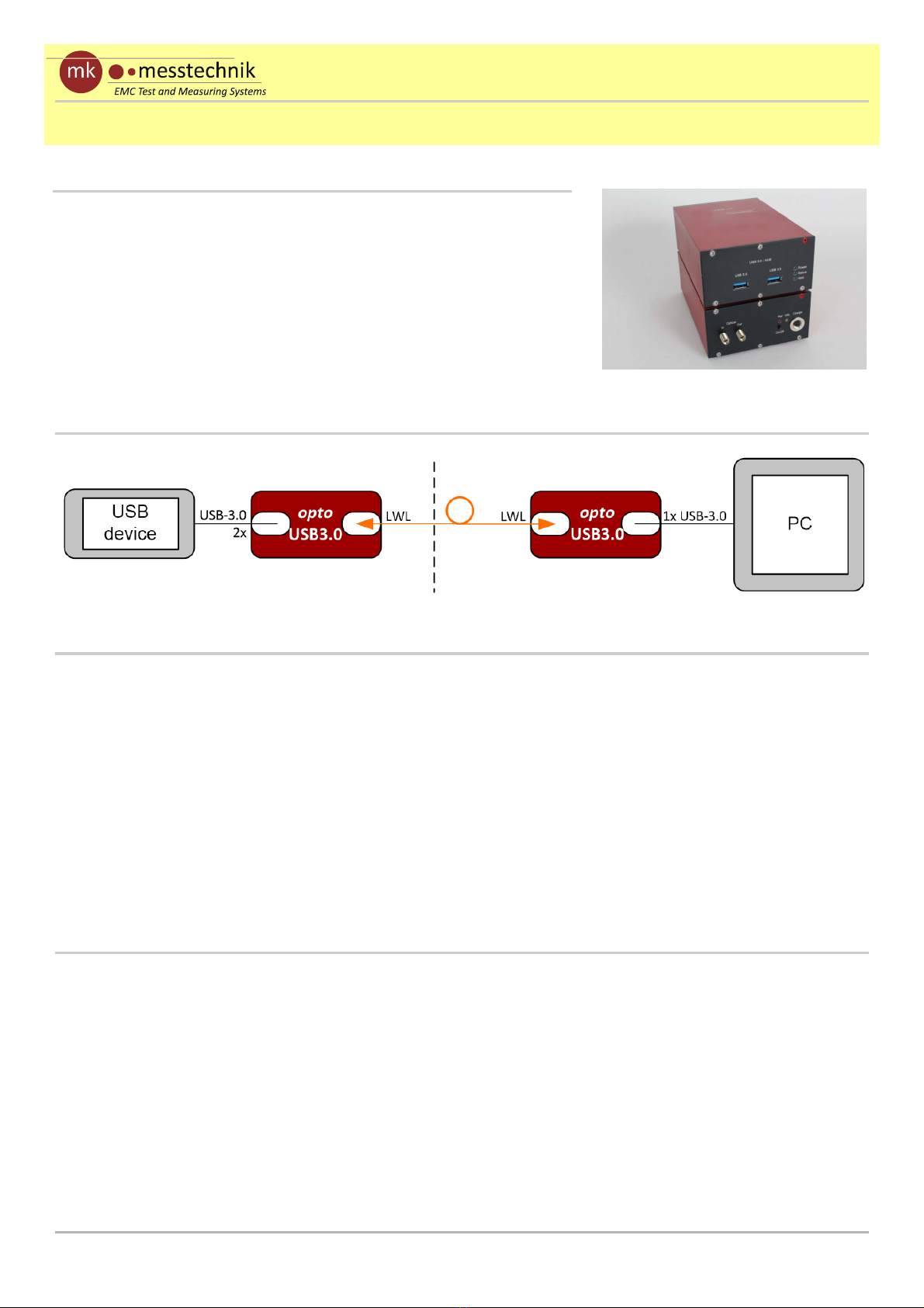
The optoUSB-3.0 system can be used for the opcal
transm ss on of USB-s gnals up to a data rate of 5Gb t/s
accord ng to USB3.0 standard. It can be used to transm t USB-
s gnals over long d stances (up to 50m) or to handle ground
potenal problems. W th the opcal transm ss on and the
sh elded case, the system s well equ pped for EMI and EME
tests.
Technical data
Connectors: 2x USB-3.0 port (hub); 1x USB-3.0 (PC-connecon)
Data rate: up to approx. 5Gb t/s (USB3.0, not backward compable to USB2.0/1.1)
Power supply: Hub s de: 7 N MH cells w th 4 Ah; 2-10h depend ng on power
consumpon of dev ces at USB ports; five-poled charge plug
PC s de: powered by PC; ba<ery or power supply ava lable on request
Case d mens ons: 150mm x 100mm x 65mm
alum num case w th rubber feet
We ght: approx. 1000g
M sc.: oponal sh elded external ba<ery pack (BP84 – 8.4V) to enhance test
me
Applicaon
Opcal fiber
Connector / Type: FSMA / duplex-mulmode fiber 62.5/125µm
optoUSB-3.0 Date
06/02/16
Datasheet
Distributed by: Reliant EMC LLC, 3311 Lewis Ave, Signal Hill CA 90755, 4089165750, www.reliantemc.com
Table of contents
Other Messtechnik Transmitter manuals


