Messtechnik U16/14-100k User manual

Manual
BV15
Analog transmitter
U16/14-100k
Distributed by: Reliant EMC LLC, 3311 Lewis Ave, Signal Hill CA 90755, 4089165750, www.reliantemc.com

Distributed by: Reliant EMC LLC, 3311 Lewis Ave, Signal Hill CA 90755, 4089165750, www.reliantemc.com

Table of contents
1 Box contents.......................................................................................................................4
2 Characteristics.................................................................................................................... 4
3 ield of application.............................................................................................................5
4 External filters.....................................................................................................................5
4.1 Differentiation: input vs. output filter.........................................................................5
5 Maintenance....................................................................................................................... 6
6 Trouble shooting.................................................................................................................7
7 Accessories / Options.........................................................................................................9
8 Contact...............................................................................................................................9
Appendix: Details and operation.......................................................................................A1
Distributed by: Reliant EMC LLC, 3311 Lewis Ave, Signal Hill CA 90755, 4089165750, www.reliantemc.com

Date:
11/19/13
U16/14-100k
Page: 4 Manual
1 Box contents
Quantity Description
1 Transmitter U16/14-100k
1 Receiver U16/14-100k
1 External filter SUB-D for EMC-tests
1 optical fiber 62,5 / 125µm
2 Chargers
1 Manual (english)
1 External battery pack (optional)
The shipment includes charged batteries. However, due to the self-
discharging of NiMH-batteries they should be recharged again before use.
Read chapter5(Maintenance) before charging the devices!
2 Characteristics
The U16/14-100k can be used to optically transmit analog voltage signals.
Because of the optical transmission, the system is very robust against EMS
(electromagnetic susceptibility). It can withstand high electric and
magnetic fields, like they appear in EMC-tests and also is optimized for low
noise emission.
The standard voltage range of the system is +/-15V. It is available with x=1
to 16 input channels. or more information about the variants, see
datasheet or call us.
Power is supplied by internal NiMH-batteries which make the system easy
to use. The U16/14-100k is prepared for the use of external batteries (with
optional battery pack).
Read chap. 5 before
charging!
Distributed by: Reliant EMC LLC, 3311 Lewis Ave, Signal Hill CA 90755, 4089165750, www.reliantemc.com

U16/14-100k Date:
11/19/13
Manual Page 5
3 Field of application
•Transmission of analog signals during EMC-tests
•Transmission of analog signals over long distances without voltage
loss (up to 100m or more, depending on timing requirements)
•Handle ground potential problems
An external filter has to be used for high level EMC-tests. The filter has to
be attached directly to the input of the transceiver located in the absorber
lined chamber. Depending on the range of use (ESD, BCI, …) there may be
different filters available. Please contact us to get the best solution.
4 External filters
An external filter mounted to the device inside the anechoic chamber has
to be used for all emissions and immunity tests. With this, a damage of the
device is avoided during immunity tests (=> obligatory! no internal filter
existing) and the emissions spectrum is reduced during emissions testing.
ilters and voltage dividers have to be connected directly to the device
since they are matched to its input-impedance (do not use an extension!).
Notice the differentiation of input- and output filters (see chapter4.1).
4.1 Differentiation input vs. output filter
If you want to transmit analog voltages from outside into the anechoic
chamber, output filters are needed (the external filter has to be mounted
to the device inside the anechoic chamber)! This has to be mentioned
while ordering the equipment, because input filters are the standard (used
to transmit signals out of the chamber). Notice that input filters cannot
simply be mounted to the receiver (output), because of different
impedances. Incorrect measurements would be the result!
•Transmission from inside to the outside of the anechoic chamber:
input filter (mounted to transmitter), Standard
•Transmission from outside to the inside of the anechoic chamber:
output filter (mounted to receiver )
The use of an
external filter for
high level EMI-tests
is essential.
If disregarded, the
system might get
damaged!
Respect the
application purpose
while choosing the
external filter!
Input- and output
filters are not
interchangeable
Distributed by: Reliant EMC LLC, 3311 Lewis Ave, Signal Hill CA 90755, 4089165750, www.reliantemc.com

Date:
11/19/13
U16/14-100k
Page: 6 Manual
5 Maintenance
Recharge batteries after use with the enclosed charger. To prevent a lazy
battery effect, discharge the devices every 5 times completely by using the
automatic switch off (Leave the system on, until it turns off automatically).
Afterwards, charge the devices as usual.
The devices have to be turned off before connecting to the charger. If this
is disregarded, the system might get damaged!
igure 5.1 shows the pinning of the charge connector. Chargers have to be
connected to pin 2 (+) and pin 4 (GND). An external supply (6…8V, 0.5A)
can be connected to pin 3 (+) and pin 4 (GND). Use only power supplies
which are certified by mk-messtechnik.
The included chargers are not meant to power the transmitter or receiver
during operation. The device outside the shielded room can be run with an
external power supply (optional). The internal device can be run with an
external battery, if needed (optional). Do not use the external power
supply or charger to power the device inside the shielded room while EMI-
tests are running. This might damage it!
Due to self-discharge issues with NiMH batteries, recharge batteries before
use, if the system has not been used for a longer time.
Do not use cleaning agents or solvents to clean the devices, only use a
slightly moistened, soft cloth.
Do not open the devices, as there are no parts inside which have to be
maintained. The opened housing can pose a fire hazard through short-
circuit currents! Please contact your distributor or the manufacturer if you
have any problems. Send in the complete system (both devices), if a
problem cannot be solved by turning the devices off and on again or by
checking the positions of the switches. Please contact us in any case before
sending in the devices.
Maximum charging
current is 1 A
Do not open the
devices!
Short cut / fire
hazard!
Figure 5.1: pinning of charge plug
Do not use charger
or power supply
during EMI-test!
Devices must be
turned off before
connecting to
charger, or else the
system might get
damaged!
Pinning of charge- /
buffer connector
Distributed by: Reliant EMC LLC, 3311 Lewis Ave, Signal Hill CA 90755, 4089165750, www.reliantemc.com

U16/14-100k Date:
11/19/13
Manual Page 7
6 Trouble shooting
The following trouble shooting list is provided to assist you while having
problems. It might let you use the system again without a long down time:
Error Possible reasons Solution
No or erroneous
transmission
Transmission does not
start properly
Noise at output
Wrong power-up
sequence
Check documentation of
hardware and position
of switches
No transmission, DC
voltage at output
No optical signal at the
receiver
System (transmitter)
turned off
Check optical fibers and
connections, change
fibers if necessary
Turn on the devices
Transmission stops Low battery
Signal of source
interrupted
Check LEDs at
transmitter and
receiver, recharge
batteries
Test source signal
directly at the device
under test
Device cannot be
turned on, cannot be
charged
Batteries damaged
Internal fuse is broke
Charger or cable
damaged
Batteries over
discharged
Send in device to the
manufacturer
Send in device to the
manufacturer
Check / replace charger
Charge batteries, maybe
use other charger (5
battery cells)
Output voltage does not
correspond to the
expected value
Voltage divider was not
taken into account
Erroneous transmission
of the settings
Wrong filter chosen /
filter not mounted
Set / Include ratio at the
oscilloscope
Turn off/on the devices
again, take care of
power-up sequence
Take operation purpose
into account (frequency
range and transmission
direction of the signal)
Distributed by: Reliant EMC LLC, 3311 Lewis Ave, Signal Hill CA 90755, 4089165750, www.reliantemc.com
Date:
11/19/13
U16/14-100k
Page: 8 Manual
Error Possible reasons Solution
Low-impedance at
input
Input wiring defective (if
system was used for
immunity tests without
external filter or over
voltage at input)
Send in device to the
manufacturer
7 Accessories / Options
Part Order number Comment
Optical fiber LWL-1-xm x = length in m, simplex
External batteries BP-60-25 6V/2,5Ah
Connector cable for
BP-60
SC-20-5m5m Length approx. 20cm
Charger with
connector plugs CH1-5m Standard charger
Input filter I-X-Y X = ratio
y = frequency limit in MHz
(ask for details)
Output filter O-X-Y X = ratio
y = frequency limit in MHz
(ask for details)
Manual MA-Ux/12-100k German or english
Distributed by: Reliant EMC LLC, 3311 Lewis Ave, Signal Hill CA 90755, 4089165750, www.reliantemc.com
Ux/14-100k Date:
19.11.13
Manual - Appendix Page A1
Appendix: Details and operation
The follo ing chapter is used to describe special details of the Ux/14-100k
system ith up to x=16 channels (+/-15V) for unidirectional transmission.
In this appendix, the maximum number of channels is being described. The
only difference if ordered ith lo er amount of channels is that the pins
ith the higher channel numbers don't have any function. The pinning of
your system is al ays printed on the housing.
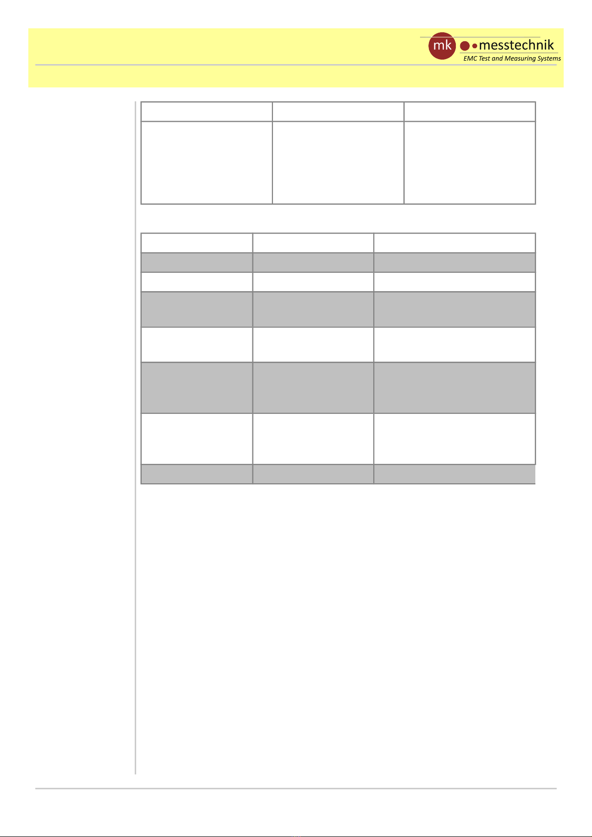
a) Housing and connectors / switches
Fig. a.1 sho s the front sides of transmitter (left) and receiver (right) ith
connectors:
•po er push button ith control LED (Pwr On/Off)
•battery information LED (Info)
•charge plug (Charge)
•optical connector FSMA(Optical In Optical Out)
•Signal detect LED (SD), only on receiver side, gives information
about connection to transmitter
Fig. a.1: Front side of the devices with connectors and switches
On / Off
Power
Optical
Out
ChargeInfo
On / Off
Power
Optical
In
ChargeInfo
SD
Front sides ith
connectors
Appendix for fully
loaded U16/14-100k.
The pinning of your
system is al ays
printed on the
housing!
Distributed by: Reliant EMC LLC, 3311 Lewis Ave, Signal Hill CA 90755, 4089165750, www.reliantemc.com
Date:
19.11.13
Ux/14-100k
Page: A2 Manual - Appendix
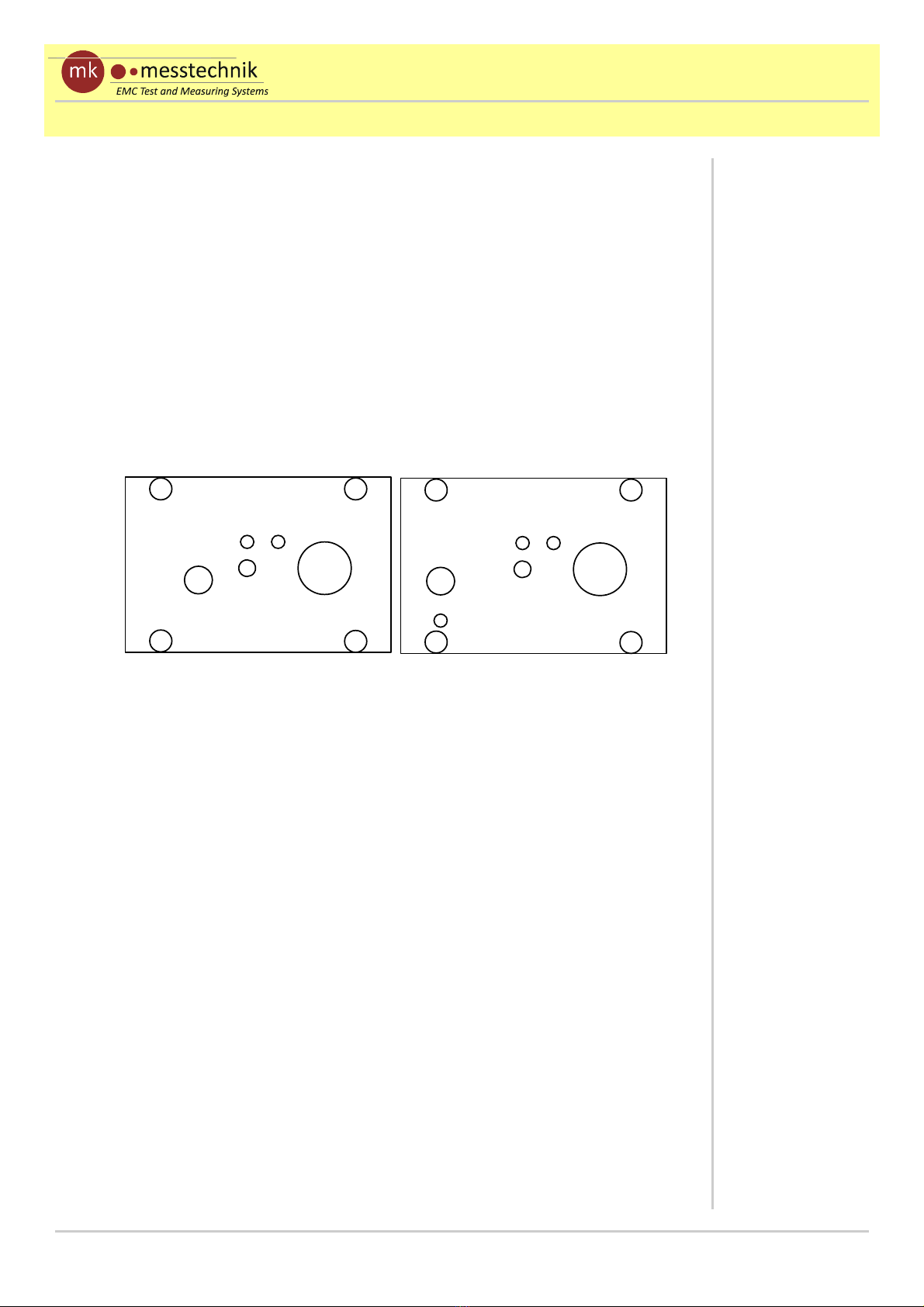
Fig. a.2 sho s the rear sides of transmitter(left) and receiver (right) ith
connectors:
•Signal connector SUB-D 25 (Input: +/ 15V 1M
Ω
||10pF) and
(Output: +/ 15V 10mA)
The housing of the SUB-D connector is connected to the aluminum case,
hich is connected to the circuit GND. This should be taken into account
during the test (possible ground loops, short circuits, parasitics to GND-
plane!). The pinning is sho n in Fig. a.2 and is also printed on the
housings.
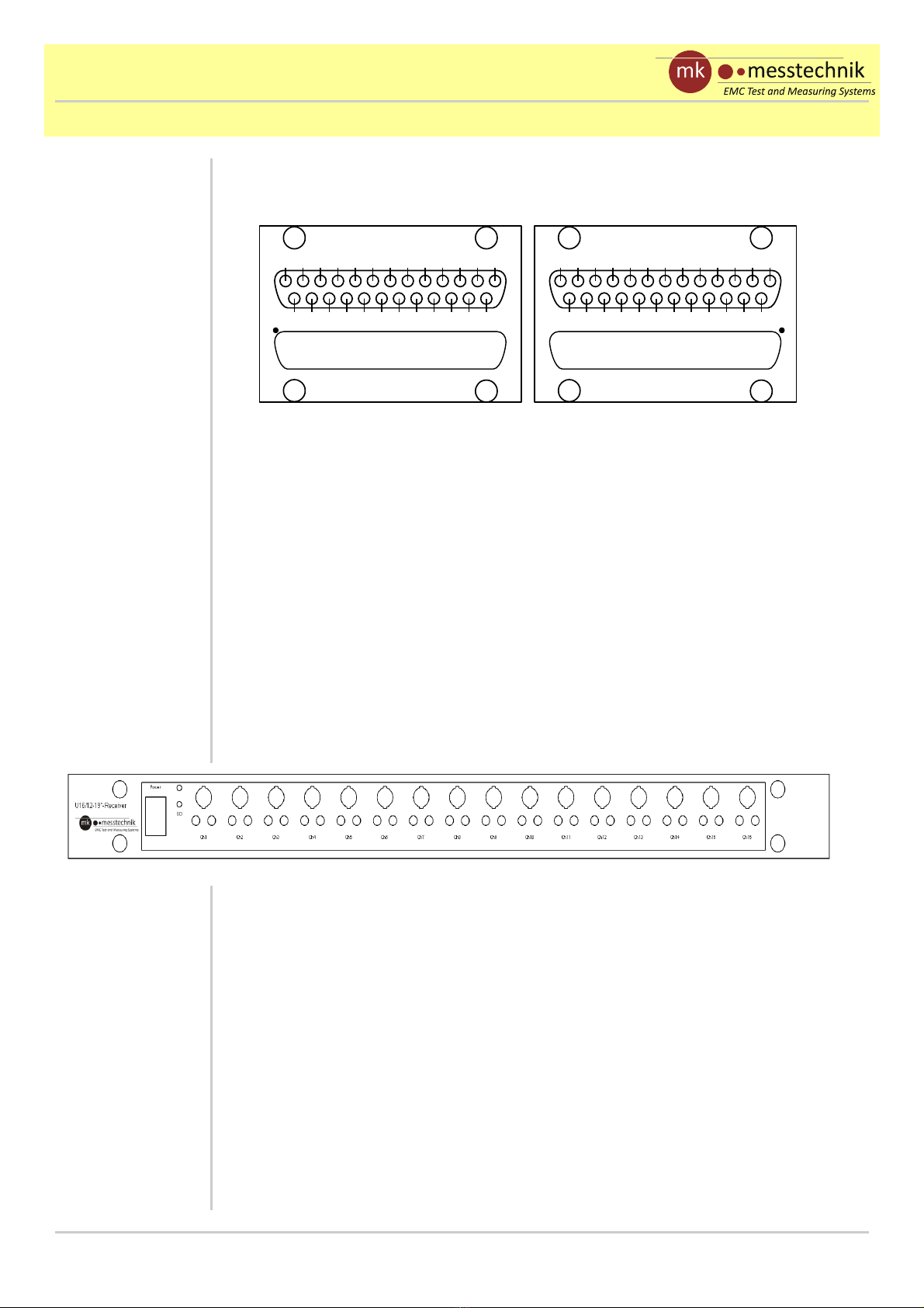
The receiver is also available as 19” rack mount kit (see Fig. a.3), hich
allo s to integrate BNC plugs at the front (pinning: inner connector is
signal) and additional other plugs in parallel (2mm Hirschmann in the
sho n case). Here, the SD LED is integrated as ell as the po er s itch.
At the rear side of the receiver, the connectors for optical input and the
po er supply (6-8V, 0,5A) are placed.
Notice, that the 19” rack mount kit is not made for use inside the EMC
chamber!
The SUB-D housing
has the same
potential as the
aluminum case.
Fig. a.2: Rear side of the devices with connectors and switches
Input:
+/-15V 1MΩ || 1 pF
GND GND
GND
GND
GND GND GND GND
GND16 14 12 10 8 6 24
1315 11 9 7 5 3 1
PIN 1
Output:
+/-15V max. 1 mA
GND GND
GND
GND
GND GND GND GND
GND2 4 6 8 10 12 1614
31 5 7 9 11 13 15
PIN 1
Rear sides ith
connectors
Your pinning is
printed on the
housing!
Fig. a.3: front side of 19" receiver with connectors
Don't use 19“ rack
mount receiver
inside the ALC!
Distributed by: Reliant EMC LLC, 3311 Lewis Ave, Signal Hill CA 90755, 4089165750, www.reliantemc.com

Ux/14-100k Date:
19.11.13
Manual - Appendix Page A3
b) peration and handling of the Ux/14-100k
•Choose and mount the correct filter for your application (cut off
frequency as high as needed and as lo as possible) to transmitter.
The filters also contain hard are for signal condition. It is essential
to use them for every setup.
•Connect the optical fiber
•Connect the analog signal cable to transmitter. It is recommended
to choose the cable as short as possible, since the transmitter input
(1MΩ || 10pF) is not matched to your application (avoid
oscillations).
•Connect the output of the receiver to a suitable high-impedance
voltage measurement device, such as an oscilloscope or multimeter.
The length of the connector cable should not be significantly longer
than 1m, since the upper frequency limit is lo ered by the parasitic
capacitive load.
•Set the voltage measurement device to the expected voltage and
time range, if necessary. If used, take optional included voltage
divider into account, hile setting / checking your measurement
device.
•Turn on all devices (no order to be recognized). Communication
bet een transmitter and receiver ill be indicated by the Signal
detect LED at the receiver.
•The Ux/14-100k system is ready to use about t o seconds after
turning on the transmitter.
•Check info LED if transmission stops suddenly!
If the transmission suddenly stops after a long duration of measurement,
check the Info LED of the transmitter (see Figure a.1). If the battery po er
falls belo 5,2V, the Info LED is s itched on. The system should be
reloaded soon. Belo 4,5V, the system is turned off automatically.
The measurements can be extended by using the optional battery pack
(BP-60) ith connector cable or a po er supply certified by mk-
messtechnik. The external supply can be connected to the system any time
(parallel). The connection to the internal battery is decoupled ith a diode.
Check info LED if
transmission stops
suddenly!
Always use external
filter! It contains
signal conditioning
hardware too and is
necessary for correct
measurements!
Distributed by: Reliant EMC LLC, 3311 Lewis Ave, Signal Hill CA 90755, 4089165750, www.reliantemc.com

Date:
19.11.13
Ux/14-100k
Page: A4 Manual - Appendix
Only use the battery pack and connector cables from mk-messtechnik!
Others might lead to a damage of the system!
nly use battery
packs and connector
cables provided
from mk-
messtechnik. ther
modules influence
EMS-performance
and might damage
the opto-system!
Distributed by: Reliant EMC LLC, 3311 Lewis Ave, Signal Hill CA 90755, 4089165750, www.reliantemc.com
Table of contents
Other Messtechnik Transmitter manuals


Popular Transmitter manuals by other brands


Tekkeon
Tekkeon myPower FM MP1100-50 user guide

Williams Sound
Williams Sound WaveCAST EIGHT user manual

BWI Eagle
BWI Eagle AIR-EAGLE SR PLUS 36-1400-4B-DC Product information bulletin

ASCOM
ASCOM A51 - user manual

Siemens
Siemens SITRANS P DS III operating instructions

Linx Technologies
Linx Technologies CMD-HHLR Series Guide


