MESTA UPS500-43 User manual

MESTA ELECTRONICS, INC.
Uninterruptible
Power
Supply
Owner's Manual
MODELS: UPS500-43,UPS750-43,
UPS750-83, UPS1000-83, UPS1250-84
11020 Parker Drive §N. Huntingdon, PA 15642
412/754-3000
SAVE THESE INSTRUCTIONS -THIS MANUAL
CONTAINS IMPORTANT SAFETY
INSTRUCTIONS
CONSERVER CES INSTRUCTIONS -CETTE
NOTICE CONTIENT DES INSTRUCTIONS
IMPORTANTES CONCERNANT LA SÉCURITÉ.


Models: UPS500-43 –UPS1250-84
i
Table of Contents
1. INTRODUCTION................................................................................................................................1
2. GENERAL DESCRIPTION.................................................................................................................2
3. INSTALLATION..................................................................................................................................4
4. OPERATING PROCEDURE...............................................................................................................6
5. RS232 INTERFACE...........................................................................................................................8
6. STORAGE........................................................................................................................................11
7. INTERNAL MAINTENANCE.............................................................................................................12
8. BATTERY INFORMATION...............................................................................................................13
9. TROUBLESHOOTING .....................................................................................................................16
APPENDIX A. UPS SPECIFICATIONS BY MODEL.............................................................................17
APPENDIX B. DRY CONTACT STATUS INDICATION........................................................................19
APPENDIX C. WARRANTY/SERVICE AND REPAIR..........................................................................20
List of Illustrations
Figure 1. UPS Battery Shelf Configuration...........................................................................................14
Figure 2. UPS Lower Battery Shelf Configuration................................................................................15
List of Tables
Table 1. UPS Software Parameters.......................................................................................................9
Table 2: RS232 Technical Specification Summary ..............................................................................10
Table 3: RS232 9-Pin D-Connector Pinout...........................................................................................10

(Page Intentionally Left Blank)

1
1. INTRODUCTION
Thank you for buying the Mesta Electronics UPS! You are now an owner of a TRULY
UNINTERRUPTIBLE POWER SUPPLY. No other system on the market can match your UPS.
SAVE THESE INSTRUCTIONS—This manual contains important instructions that should be followed
during installation and maintenance of the UPS and its batteries. Please read this manual thoroughly
before installation and operation of your new unit.
WARNING—Your UPS contains up to eight 12 volt batteries wired in series providing a total nominal
DC voltage of 96 volts. This voltage is used to power the UPS when the AC utility is not available.
Because of the presence of this high voltage energy source, even when the power cord is not plugged
in, certain precautions must be taken to avoid possible injury should you need to enter your unit.
Before attempting to enter your unit, read the sections of this manual on "Internal Maintenance" and
"Battery Information" for important safety precautions.

2
2. GENERAL DESCRIPTION
As computers become increasingly fundamental to today's businesses, protection against power
disruptions has never been more critical; and since vital data and hardware are threatened by routine
sags, surges, spikes, and transients—as well as major blackouts—protection must be constant and
instantaneous.
The Mesta UPS system provides this kind of comprehensive protection by maintaining a clean, well-
regulated flow of power to critical loads, regardless of the quality of incoming AC line power. It
remains in a constant state of readiness, so there is no time delay in compensating for AC line
failures.
Unlike many competitive units, the Mesta UPS system is truly uninterruptible. It remains in a
constant state of readiness, so there is no time delay in compensating for AC line failures. In contrast,
other systems may exhibit delays of 4 to 10 milliseconds—long enough to cause serious losses of
data or equipment.
Unique microcontroller intelligence plus state-of-the-art components and manufacturing procedures
yield outstanding capabilities in the Mesta UPS system. Using a proprietary pulse-width-modulation
technique, the microcontroller directs the system to produce a very low harmonic, high quality sine
wave output—perfectly matched in phase and voltage to the AC power line. The result is a
completely seamless transfer of the load from the inverter to the utility and vice versa during a power
disturbance or outage.
This zero-transfer-time feature, combined with a high frequency switching and custom magnetics,
results in a high operating efficiency of at least 92 percent and a total harmonic distortion of less than
one percent.
Because the microcontroller continually monitors the load and the power line, the Mesta UPS system:
•Starts under load with no damage to itself or the load.
•Handles nonlinear loads that require users of other UPS systems to buy more expensive,
higher rated units than they would otherwise need.
•Provides current limiting and short-circuit protection. The UPS provides a 300% overload
current limit for a finite time (the UPS1250 unit provides 400%), and a short circuit placed
directly across the output will not damage the UPS or the load.
The Mesta UPS system also features:
•High Reliability thanks to the large-scale integration and generous overrating of all power
components. Its modular design provides for quick and easy maintenance should it ever be
needed.
•A more compact footprint and lighter weight than other UPS units, because of its custom
transformer and intelligent operation.
•Quiet operation .5KVA through 1.25KVA units produce less than 35 dBs of audible noise, a
level that is virtually indistinguishable from ambient noise. (In contrast, most other similarly
sized UPS units are many times louder, generating from 45–75 dBs.)
Straightforward controls make the Mesta UPS easy to operate, and audible and visual signals provide
clear indication of system status. In the event of a power line outage, the system:
•Sounds an intermittent alarm after seven seconds. (The seven second delay eliminates
nuisance alarms from minor fluctuations.)

3
•Supplies power at maximum load for 8 to 20 minutes, depending upon model. (See
specifications for your specific model.) These times will be longer at lesser loads.
•Sounds a continuous 30-second alarm when the usable battery has declined to 10 percent of
its full capacity.
•Automatically goes into a state of inactivity once regulated output can no longer be maintained,
waiting for the return of AC line availability. During this state of inactivity the logic will continue
to look for the AC power to return in order to restore normal operation. If no AC power returns,
however, after 2 hours the entire system will shut down, to protect the batteries from being
deep discharged.
Once the AC power returns, the system's microcontroller employs optimum charging techniques to
extend battery life while minimizing charging time. The microcontroller follows a unique algorithm by
which it regulates the charging process and enables a minimal recharging time. This very special care
given to the batteries also eliminates the corrosion buildup you may find on the terminals of other
systems that employ trickle charge or other techniques for recharging batteries.
Your unit may come with one or more options indicated by suffix letters following the end of your
model number. Some explanation is necessary for a few of these options:
-BAutomatic Bypass Option. Units equipped with this option have an internal "bypass" relay that
normally selects the UPS output voltage to be directed to the output receptacle of the UPS.
However, in the unlikely event that a failure occurs in the UPS and it is unable to continue to
drive the load, this relay automatically switches to allow the utility to drive the load directly. Thus,
if the utility is present, the load will continue to be powered uninterrupted. One should also note
the following feature of this option: If the UPS is turned off from the from panel, the "bypass"
relay will switch to power the load from the utility so the load will not power down. To power
down the load, either shut the load off, unplug the load from the UPS, or unplug the UPS from
the utility just before or after the UPS is turned off.
-IIsolation Option. Units equipped with this option have outputs that are totally transformer
isolated from the utility (even if the unit is equipped with the -B option and the unit is in the
bypass mode). The output neutral is internally connected to chassis ground in these units. This
option results in a UPS that is slightly larger and slightly less efficient than standard models.
YOUR INVESTMENT IN MESTA'S TRULY UNINTERRUPTIBLE POWER SUPPLY INSURES THE
VALUABLE POWER PROTECTION YOU NEED.

4
3. INSTALLATION
Unpacking: Before unpacking your unit, examine the shipping carton for damage. If there is any
obvious damage, report it immediately to the dealer or carrier. If no damage is found, unpack the unit
and inspect it for shipping damage. Again, in case of any damage, report it directly to the dealer or
the carrier.
Environment: The MESTA UPS is designed to be used in a temperature controlled, indoor area free
of conductive contaminants, having a temperature range of 0–40°C and relative humidity of 0–95%,
without condensation. The site should not be excessively dusty or dirty. Clearances should be
provided to the front and back of the unit so as not to block air inlets and outlets. Also, keep the top
of the unit clear of objects. The unit should never be used to sit or stand on.
Location of Unit: The UPS should be in close proximity to the protected equipment: the longer the
AC wire runs, the more voltage drop and more risk of noise getting back into the system there are.
Voltage/Power Rating: Make sure that the voltage and power rating match the available line voltage
and load requirements. This can be done by comparing the input and output information printed on
the rating plate of the UPS with your requirements.
Power Cord Plug-in: Having verified voltage and power ratings, you are now ready to plug the UPS
into the AC power. Your unit will have a detachable power cord that was shipped with the unit. Use
only this cord with your UPS. Do not substitute other cords in its place as their current ratings may not
be sufficient for your UPS needs. Plug the detachable cord into the UPS input receptacle. Now plug
the AC power cord into the utility receptacle at your facility.
UPS Power On: Having plugged your UPS into the AC utility, you may now turn on your UPS using
the front panel power switch. Press the "ON" button. After a few seconds delay, the UPS will begin
operating. Initially (for a very short period of time) all front panel lights will flash on simultaneously,
and the audible alarm will beep once. Then the UPS will power up with the "UPS ON" green front
panel light on. If the AC power utility is present and within tolerance of the UPS microcontroller
standards, the "ON LINE" and "BATTERY STATUS" green front panel lights will also be on. The
yellow "ON BATTERY" light will be on momentarily until the microcontroller determines that the UPS is
able to derive power from the AC power utility and no longer needs the batteries. Then the UPS will
be drawing the average power that it needs from the utility only, and this light will cycle off.
Fault Checking: If the normal UPS Power On sequence does not occur for you, perform one of the
following alternative actions:
1. If the "ON LINE" light does not come on, and the yellow "ON BATTERY" light remains on (also
eventually to be accompanied by an audible beeping alarm), recheck your connections to the AC
utility. (Also check to see if any breakers or fuses in that particular circuit of your building are
open.) If after rechecking, no problem is found, and the UPS will not perform according to the
proper procedure described above, contact the factory for further assistance.
2. If the normal UPS Power On procedure is not observed, and the warning conditions described in
alternative #1 are also not observed, contact the factory for further assistance.
Connecting the Load: Assuming that normal operation was observed, you can now plug your loads
into the receptacles at the back of the UPS. If during this procedure the "OVERLOAD" red light
comes on along with an audible alarm, your load is too large for the UPS, and some must be removed
or the UPS will shut down.

5
Installation Complete: Assuming an overload doesn't occur prior to attaching and turning on all
loads, you have completed the installation procedure of your UPS. From here on there is no special
powering up or powering down sequence that needs to be followed for either your load equipment or
the UPS. This installation procedure is only necessary to insure that the UPS did not incur any
internal shipping damage and that your building's AC utility is getting to the UPS.
Computer Terminal Connections: It is also suggested, but not required, that you connect a terminal
or computer to the RS232 interface (see section of the manual pertaining to this interface). Through
this communications interface, you can obtain additional useful data that is either very difficult to
determine or is not explicitly available from the front panel lights. One of these parameters is the load
on the UPS. The microcontroller will indicate the ampere and volt-ampere load on the UPS. From this
information you will be able to determine if additional loads may be added in the future. It is advisable
that the steady state load observed on the UPS be limited to approximately 80 to 85% of the full rating
of the UPS under normal operating conditions. This should provide enough margin under most
operating conditions.

6
4. OPERATING PROCEDURE
SYSTEM TURN-ON
Once plugged in and turned on, the MESTA UPS will be supplying power to the load. The green
"UPS On" light will be on solid, the green "On Line" light will be on solid and the yellow "On Battery"
light will be off solid, if the utility (AC line) is present. The green "Battery Status" light will either be on
solid or flashing, depending on the charge status of the battery. The above light combinations
indicate normally conditions. If the utility fails or goes out of voltage or frequency tolerance, the "On
Line" light will go off and the "On Battery" light will come on (indicating that the UPS is using power
from the battery to power the load). In addition, if the utility is gone for more than 7 seconds, an
intermittent audible alarm will sound to warn that the UPS is using battery power. This alarm will
continue for 30 seconds or until the "Alarm Reset" button is pressed.
Occasionally, the "On Battery" light may flicker while the "On Line" light is lit, as the utility voltage or
the load changes. This is normal. Other light combinations indicate abnormal conditions. See
explanations below for additional information.
UPS On (green) Indicates UPS is turned on.
On Line (green) On solid indicates AC line voltage and frequency are within tolerance. Off solid
indicates AC line is not within tolerance. Flashing once per second with a 50% duty cycle
indicates a problem (see On Battery description below).
On Battery (yellow) On solid indicates UPS is drawing power from the batteries to supply the load.
Flashing once per second with a 50% duty cycle indicates UPS output is shut down due to an
abnormal condition. In this case, the status of the "On Line", "Battery Status", and "Overload"
lights indicate the reason for the abnormal shutdown as follows:
1) If all three of these other lights are also flashing in unison, UPS has detected an internal
failure and you need to contact the factory. If possible, while the UPS is flashing the lights in
this manner, press and hold in the "Alarm Reset" button and observe which lights are on and
which are off, while holding in the button. Record your observations, as this is diagnostic
information that will help the factory determine the problem. Note: the audible alarm will sound
continuously while you are holding in the "Alarm Reset" button.
2) If the "Overload" light is on solid, UPS shut down because of an overload. Check your load
for possible problems; then, press the "Alarm Reset" button to restart the UPS. You must wait
at least 30 seconds after the UPS has shut down from an overload before the UPS will let you
do this.
3) If the "Battery Status" light is off completely, then the UPS shut down because the batteries
are discharged. The AC line must be present for the UPS to restart when its batteries are
discharged. If the "On Line" light is on and the UPS is not running, press the "Alarm Reset"
button to restart the UPS.
Battery Status (green) Indicates charge status of batteries as follows:
On solid -- batteries are at least 90% charged.
Off solid -- batteries are discharged (less than 2%).
Flashing with 75% duty cycle -- 50-89% charged.
Flashing with 50% duty cycle -- 25-49% charged.
Flashing with 25% duty cycle -- 10-24% charged.

7
Flashing with 10% duty cycle -- 2-9% charged. When batteries are discharged to below 10%
level, solid audible tone is generated for 30 seconds or until "Alarm Reset" is pressed. (The
level of the Low Battery alarm can be changed using the FSET Routine, section 5 RS232
Interface).
Overload (red) Solid on accompanied by a solid audible tone (which cannot be silenced by the
"Alarm Reset") indicates the UPS output is being overloaded. This annunciation will remain
until either the overload disappears or the UPS shuts down.
Flashing 3 times quickly every second indicates the UPS has detected a diagnostic condition,
but is still running. However, for many such diagnostic conditions, the UPS will not be able to
use the AC line, so when the batteries are discharged, the UPS will shut down. This condition
most likely means that an internal UPS failure has occurred. Perform an orderly shutdown of
your equipment and contact the factory. If possible, while the UPS is flashing the lights in this
manner, press and hold in the "Alarm Reset" button and observe which lights are on and which
are off, while holding in the button. Record your observations as this is diagnostic information
which will help the factory determine the problem. Note: the audible alarm will sound
continuously while you are holding in the "Alarm Reset" button.
Note that whenever the "Alarm Reset" button is pressed, the audible alarm emits a solid tone for as
long as the button remains pressed. Also, all lights will be on during this procedure unless the UPS is
in a fault mode. In this case, the status of the lights indicates the problem.
To Test the Batteries: The UPS is programmed to test the internal batteries automatically and under
load. The procedure for starting this 60 second test is to hold the "Alarm Reset" button in for at least
5 seconds. Release the button, then touch it again three more times in short succession. This will
signal the microcontroller to begin testing the batteries. Within a few seconds the battery test will
begin, and the alarm will beep 3 times in repetitive cycles. This lets you know the test is in progress.
To terminate this test early, press the "Alarm Reset" button again. Test results will be indicated by the
"Battery Status" light as shown above. To obtain more precise results, use the RS232 interface
provided with the system.

8
5. RS232 INTERFACE
For sophisticated applications, the Mesta UPS system provides an RS232 communications interface
which can link the microcontroller with a remote computer or terminal. This two-way link allows users
to 1) collect detailed information on power usage and other characteristics of the load to which the
UPS is connected and 2) remotely control the UPS or the load. (For example: a system can be
developed to alert the computer to automatically save data and shut itself down when the UPS battery
power is dwindling and no emergency generator is available.)
Any computer or terminal equipped with an RS232 serial port capable of a 1200 baud rate can be
used to communicate with the UPS. If a terminal is being used, one can begin sending commands to
the UPS as soon as a 3-wire hardware interface is in place. If a computer is being used, a
communications software package that allows the computer to act as a terminal must be executed on
the computer. Mesta provides this software on a 5¼" or 3½" diskette. Once communication has been
established with the UPS, the UPS will provide a ">" prompt, which signals the operator to enter a
command.
Software Commands: UPS information may be examined using the following commands:
Sn -Status command displays the present status of a parameter. To display the status of a particular
parameter, type Sn<cr>. "S" indicates the status command, "n" represents 1 to 3 letters, from
A to S, designating the desired parameters to observe, and <cr> indicates a carriage return (or
"Enter" key) which is used to terminate the command. Table 1 contains the list of available
parameters that may be examined. As an example, if the present AC line voltage is to be
examined, type SA <cr>. If the present AC line voltage, UPS output voltage and battery
voltage are to be examined, type SABC<cr>. By entering S<cr>, with no parameter letter, a
status update of 18 of the most useful parameters can be observed.
Vn -View command is similar to the Status command, except the View command will continually
display the status of the selected parameter until the "Escape" key on the computer or terminal
keyboard is pressed. To continually view the status of a particular parameter, type Vn<cr>.
"V" indicates the View command, "n" represents 1 to 3 letters, from A to S, designating the
parameters to be viewed, and <cr> indicates a carriage return (or "Enter" key) which is used to
terminate the command. Again, Table 1 contains the list of available parameters that may be
examined. As an example, if the AC line voltage is to be viewed continuously, type VA <cr>.
By entering V <cr>, with no parameter letter, a continuous view of the status of 18 of the most
useful parameters can be observed.
En -Extreme command will monitor and display the extreme or peak value of the first selected
parameter until the "Escape" key on the computer or terminal keyboard is pressed. The UPS
will continually monitor the first selected parameter and display new values only if a greater
value (for the first selected parameter) has occured. To view the peak value of a particular
parameter, type En<cr>. "E" indicates the Extreme command, "n" represents 1 to 3 letters,
from A to S, designating the parameters to be viewed, and <cr> indicates a carriage return (or
"Enter" key) which is used to terminate the command. Again, Table 1 contains the list of
available parameters that may be examined. As an example, if the peak value of the AC line
voltage is to be viewed, type EA <cr>. The UPS will continue to monitor the AC line voltage
and display a new value only when the new value is greater than the one displayed.
<Esc> -The "Escape" key can be pressed at any time to abort any command. After pressing the
"Escape" key, the UPS will display <ESC> to indicate such a key was pressed followed by a
new ">" prompt. At such a time a new command can be entered.

9
Table 1. UPS Software Parameters
Letter to Use UPS Parameter Notes
AAC line voltage (in RMS volts)
BUPS output voltage (in RMS volts)
CBattery voltage (in DC volts)
DAC line amps (in RMS amperes)
EUPS output current (in RMS amperes)
FCurrent draw from battery (in DC amperes) 1
GLine power (in watts)
HLoad power (in watts)
IBattery power (in watts)
JUPS line volt-amps input
KUPS volt-amps output
LBattery charge remaining (percent) 2
MAC line frequency (in Hertz)
NUPS output frequency (in Hertz)
OTemperature (in °C) on heatsink
PUPS line status
QUPS mode
RFault status
SInverter DC voltage (DC volts)
None Parameters A through R displayed all at once
Notes on the MESTA UPS Parameters:
1. Current draw from the batteries is "+" if batteries are being discharged and "-" if batteries are
being charged. A small positive or negative value of .1 or .2 amps may not necessarily reflect
that the batteries are being charged or discharged.
2. The accuracy of the percentage of battery charge remaining depends on operating conditions
and the present loading of the UPS. The accuracy will be much more precise at the lower
percentages than it is at the higher percentages (where the performance curve flattens and a
perfectly correct interpolation is more difficult—in the 92–100% range).
Changing the Programmable Parameters (FSET):
There are four programmable parameters of 1) frequency range allowed, 2) slew rate (how fast you
allow the output to change frequency), 3) On Battery alarm and 4) Low Battery alarm all of which are
in the non-volatile memory.
To see the parameters being used:
•Type FSET <cr>. The UPS' current operating values will be listed.
To change these parameters:
•Type FSET;CH <cr> to enter the function set routine, and the first of the four programmable
functions will appear on the screen with the question of whether you'd like to change that
particular parameter.
•As you respond by typing a Y(yes) or N (no), for the first two parameters, the screen will then
indicate the value range within which you can program the function.
10
For the Battery Alarms:
•You will be prompted to choose from the modes of Enable (5-60 second annunciation duration
or until manual reset with the Alarm Reset button), Disable (off -no audible annunciation) or
Forever (continuous or until manual reset with the Alarm Reset button).
•As you respond by typing 1 (enable), 2(disable), or 3 (forever), for each, the screen will then
prompt for the annunciation duration. Enter a value which is an increment of 5. This value
defines the annunciation duration for whichever warning(s) "Enabled".
•Lastly, you will be prompted to enter the % battery charge at which the Low Battery alarm
occurs. Enter a value which is an increment of 5. The UPS will now return to its normal
operation automatically.
Options:
To view the options within this particular unit:
•Type OPT <cr>. Your screen will show the following:
Table 2: OPT Command Output
UPS Option Configuration (Version x.xx)
Volt-Amps
Crest Factor
Int Batt AH (amp-hours)
Voltage In
Voltage Out
TX type # (transformer type #)
Batt Voltage
Table 3: RS232 Technical Specification Summary
CONNECTOR: 9 pin D female
FORMAT: ASCII, 1 start bit(0), 8 data bits, 1 stop bit(1)
BAUD RATE: 1200
PARITY: none
DUPLEX: full
PROTOCOL: None used. Interface is simple 3 wire (RXDATA, TXDATA, and
GND) with no hardware or software handshaking.
Table 4: RS232 9-Pin D-Connector Pinout
PIN 2: Transmit Data
PIN 3: Receive Date
PIN 5: Signal Ground

11
6. STORAGE
Battery Life: The MESTA UPS should be stored with the batteries fully charged. Storage
temperature should be maintained between -20°C and 40°C. The life of the batteries may be greatly
reduced if stored at temperatures exceeding 30°C for extended periods of time. Optimal storage
temperature for maximum battery life is 20°C or lower.
Power Switch: Make sure the power switch to the UPS is off prior to storing the UPS. Also, batteries
may be permanently damaged if not removed from storage periodically and fully recharged at least
once every 6 months. To recharge batteries inside UPS, simply remove the UPS from storage and
connect the unit to an AC power source and turn it on for a minimum of 4 hours (make sure batteries
are being charged by monitoring the lights on the front panel of the UPS). Then you may turn the unit
off again and return it to storage for up to another 6 months.

12
7. INTERNAL MAINTENANCE
IIWARNING
Only qualified technicians or supervised personnel should open the UPS and only after ALL of
the following WARNINGS and instructions are read and fully understood.
Mesta's UPS has been designed to provide unprecedented reliability; therefore it requires little or no
maintenance. However, should internal maintenance be required, please adhere to the following
warnings and instructions.
IIWARNING
Risk of Electric Shock exists inside the UPS. The UPS receives power from the AC source
(via the AC power cord) and a DC source (via the internal batteries). Maintenance personnel
must be aware of this hazard or they may be exposed to an electrical shock hazard that could
result in death or injury or damage to the UPS or its electrical loads.
IIWARNING
The UPS internally contains capacitive components which remain energized even after power
to the UPS has been turned off. A unit's front panel LEDs are functioning normally such that
when the unit is turned on, one or more of the LEDs lights up steadily or periodically, and when
the unit is then turned off, all LEDs go off within 20 seconds. Under these circumstances the
voltage across these capacitive components will be minimized to safe levels within 1 minute of
turning the UPS off. If, however, the LEDs never come on or never go off during operation of
the "ON" and "OFF" switches, a problem exists with the unit. Under such conditions it is
possible for hazardous voltages to remain for longer periods of time. If such a malfunction
exists, it is advisable not to open the unit. Instead, contact the manufacturer or nearest repair
center.
Instructions for Opening and Closing the UPS: Before opening the unit, make sure the UPS power
switch is "OFF" and the AC power cord is unplugged. Make sure all front panel LEDs go off. Next,
remove the battery fuse, located at the upper left side of the back of the unit, by turning the fuse cap
counterclockwise. Then pull out fuse/fuse cap, being careful to touch only the plastic cap while
extracting the fuse. To avoid risk of Electric Shock, DO NOT probe into empty fuse holder.
Four #6-32 screws must be removed from the bottom of the unit so the UPS cover can be removed.
To access these screws, either lay the unit on its side or position the end of the UPS slightly over the
edge of a work bench so you can reach two of the screws at a time from below. Once the four screws
are removed, set the unit upright and slide the cover towards the rear of the unit.
DO NOT try to enter the unit any other way (such as removing screws from back of unit) as such an
action may result in risk of Electric Shock. If extensive work is to be done within the UPS, remove
the batteries from the unit as described in the "Battery Information" section of this manual. When
servicing inside of unit is complete, return the cabinet cover to its original place on the UPS and
replace the four #6-32 screws in the bottom of the chassis. After making sure power switch is still in
the "OFF" position, place fuse cap on one end of the fuse (if the two have become separated) and
screw fuse/fuse cap clockwise into empty fuse holder, being careful to touch only the plastic part of
the cap.
13
8. BATTERY INFORMATION
The standard batteries supplied in the MESTA UPS are sealed lead-acid maintenance-free 12 volt 6.5
amp-hour batteries. These batteries are wired in series to provide a total nominal voltage as follows:
Number of Batteries:
48
Total Nominal Voltage:
48VDC 96VDC
The nominal voltage found in the larger models is 96 volts DC. Expected battery float life is 5 years at
room temperature (70°F), although frequent discharges and high ambient temperatures will shorten
battery life. The standard battery supplied is designed to be kept at a constant 13.5 to 13.8 volts.
The microprocessor is set to charge the batteries to 13.7 volts. It will recharge the fully discharged
batteries in a relatively few hours. The run time that one can expect is dependent on the magnitude
of the load and the age and state of charge of the batteries.
IIWARNING
A BATTERY CAN PRESENT A RISK OF ELECTRICAL SHOCK OR BURN FROM HIGH
SHORT CIRCUIT CURRENT. OBSERVE PROPER PRECAUTIONS. WHEN REPLACING
BATTERIES, USE THE SAME NUMBER AND THE FOLLOWING TYPE BATTERIES: SEALED
LEAD ACID. PROPER DISPOSAL OF BATTERIES IS REQUIRED. REFER TO YOUR LOCAL
CODES FOR DISPOSAL REQUIREMENTS. Do not dispose of batteries in a fire -they may
explode. Do not open or mutilate any battery. Released electrolyte is harmful to the skin and
eyes. It may be toxic. Only qualified technicians or supervised personnel should remove and/or
replace the batteries. Mistakes in connecting or disconnecting can cause connections to arc or
weld and could result in severe bodily harm or damage to the UPS.
IIATTENTION
UNE BATTERIE PEUT PRÉSENTER UN RISQUE DE CHOC ÉLECTRIQUE OU DE BRÛLURE
PAR TRANSFERT D'ÉNERGIE. SUIVRE LED PRÉCAUTIONS QUI S'IMPOSENT. POUR LE
REMPLACEMENT, UTILISER LE MÊME NOMBRE DE BATTERIES DU MODÉLE SUIVANT:
SEALED LEAD ACID. L'ÉLIMINATION DES BATTERIES EST RÈGLEMENTÉE. CONSULTER
LES CODES LOCAUX À CET EFFET.
Instruction for Removing UPS Batteries:
Mesta has designed this unit to provide maximum battery reliability, thus requiring little or no
maintenance. However, should a battery problem be detected, please adhere to the following
instructions and preceding warnings. The unit has been designed to allow easy access and
replacement of the batteries by qualified technicians or supervised personnel.
Removing the batteries necessitates opening the UPS cabinet. Follow the procedure for opening the
UPS outlined in the "Internal Maintenance" section of this manual. The following precautions should
be observed while working on batteries:
1) Remove watches, rings, or other metal objects.
2) Use tools with insulated handles.
3) Do not lay tools or metal parts on top of batteries.
4) Do not touch battery terminals to chassis (watch for inadvertent contact that can occur if not
being careful when removing lead wires to battery terminals).
5) Make sure battery fuse located external to the UPS, on its upper back side, has been
removed.
14
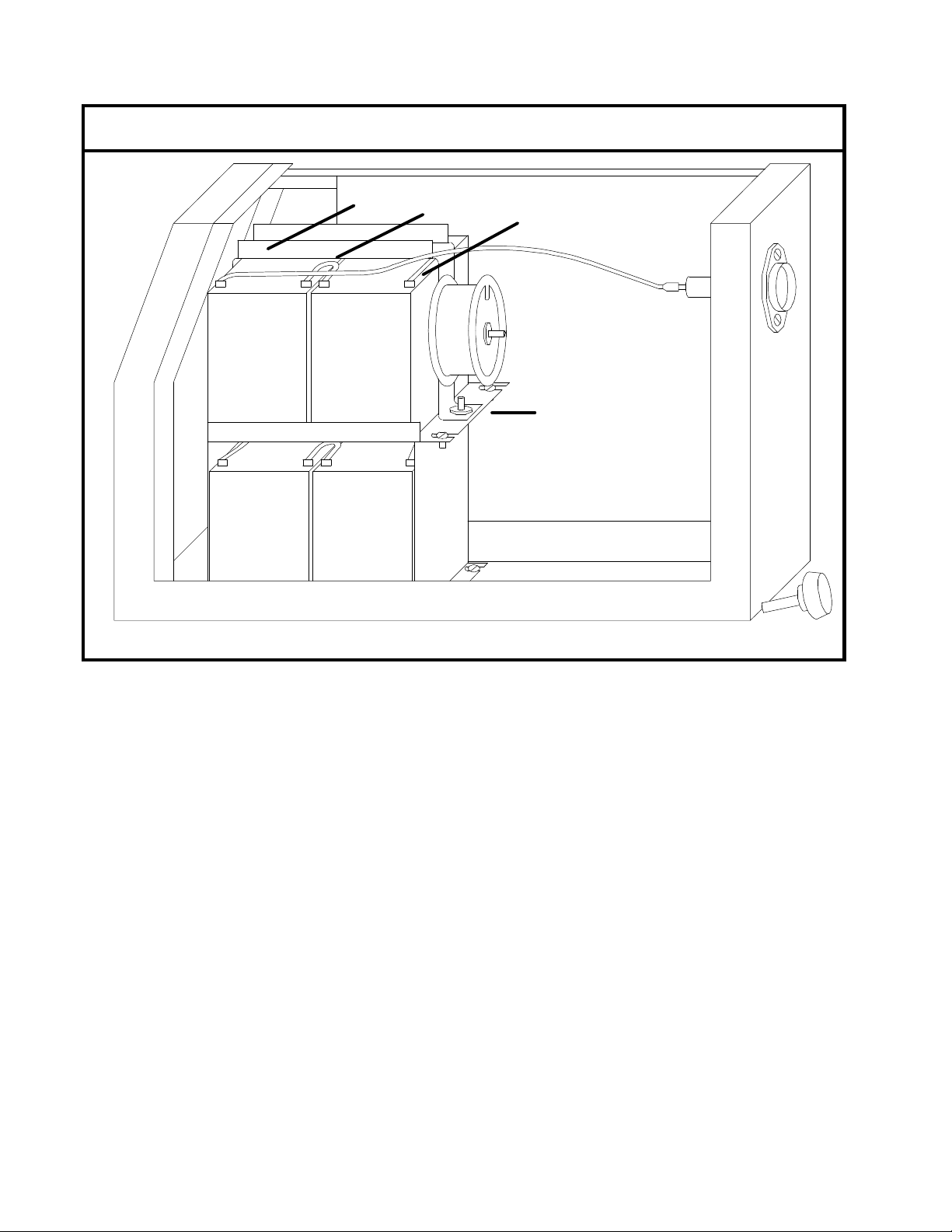
Figure 1. UPS Battery Shelf Configuration
1
23
4
Once the unit is off and you have removed the AC plug, DC fuse and unit cover, you must then
remove the white B+ wire from the far upper left battery (as viewed above). Figure 1 shows the
battery configuration for a 4 battery UPS. If you have an 8 battery UPS, there will be 4 batteries on
each shelf. If you have a 2 battery UPS, proceed directly to figure 2.
To remove the bracket holding the upper batteries,
1) Remove the 8-32 hex nut on the right side of the bracket (below the inductor coil).
2) Pull up on the right side of this bracket in order to release its tab (located on the left side)
which is inserted in the slot of the bracket below. Then slide the batteries to the right so that
the bracket handle will clear the case. Set the bracket, coil and wires aside.
3) Next remove the BC wire on the far right side of the top shelf batteries. (This is the wire
coming from the left-most terminal on the batteries on the lower shelf. BE CAREFUL TO
ISOLATE THE LOWER SHELF BC WIRE, BECAUSE THIS IS THE SAME AS THE
CHASSIS. To touch the chassis (or elsewhere) could short the lower shelf batteries.
4) Detach the wires connecting the top shelf batteries in series. The top shelf batteries are now
ready for removal and/or replacement.

15
Figure 2. UPS Lower Battery Shelf Configuration
1
2
3
4
5
To remove the lower shelf batteries,
1) Remove the two 8-32 screws holding the upper platform in place.
2) Lift up on the right side of this platform in order to release its tabs (located on the left side)
that are inserted in slots in the bottom of the UPS chassis.
3) Next remove the BC wire on the far left side of the lower shelf batteries (as viewed in the
illustration). If you have a 2 battery UPS, this wire is labeled B+.
4) Remove the B-wire on the far right side of the lower shelf batteries.
5) Upon removal of the remaining wire connecting the batteries in series, the batteries are free
for removal/replacement.
Reverse the above procedures to re-install batteries.
IIWARNING
Caution on re-installation of batteries—Be sure that the battery wires are not pinched
anywhere between any platform, bracket, etc. as this could possibly cause an Electrical
Short.

16
9. TROUBLESHOOTING
In the case of a UPS shutdown check the status of the front panel lights before
attempting to restart the system. This information is critical in determining why the
UPS shut down.
1. Check and record the status of each of the four front panel lights. (on, off, flashing)
2. If the OVERLOAD light is on and the UPS ON light is flashing the system shut down due to an
overload.
3If all four front panel lights are flashing the system has gone into a diagnostic mode.
4. If the system is in a diagnostic mode press and hold the reset button and record the status of
the four front panel lights. (on, off, flashing)
5. If the system is in a diagnostic you may also check the fault status indication through the
RS232 communications interface.
6. At this point it is recommended that you contact a Mesta representative for assistance.
This manual suits for next models
4
Table of contents
Other MESTA Power Supply manuals

Popular Power Supply manuals by other brands


Telecom
Telecom RPS-1230-SWM quick start guide

SECO-LARM
SECO-LARM Enforcer EAP-5D1 Specification sheet

West Mountain Radio
West Mountain Radio PWRgate PG40 owner's manual

TDK-Lambda
TDK-Lambda GENESYS 1500W Technical manual

Powerware
Powerware 3110 user guide

MFJ Enterprises
MFJ Enterprises MFJ-4125 instruction manual