BRUEL & KJAER 2804 User guide

Microphone
Power
Supply
Type
2804
Two Channel Battery Driven
Power Supply Type 2804
This
battery driven,
portable
power
supply
provides
power
for
two
2619
preamplifiers
. In
addition
, it
provides
either
28
V
or
200
V
polarization
voltage
for
B &K
condenser
microphones
and 2
outputs
of
28
V and 2 mA each
for
driving
vibration
pick-up
preamplifiers. The Type 2804 is part
of
the B & K
module
system, making
it a
convenient
part
of
a complete
sound measuring system.


Two
Channel Battery Driven Power Supply
Type 2804
MAY1970


CONTENTS
1.
INTRODUCTION
........•.........••.....••..•••••••.•
3
2.
OPERATION
.............................••.••.•••.•.
4
2.1. Terminals and Controls
.................•......
4.
2.2. Installation in Module System
.....•.............
9
3. DESCRIPTION
.........•..•.....................•....
11
4. OTHER INSTRUMENTS
AND
THE 2804
........•....•....
12
4.1. Condenser Microphones . . . . . . . . . . . . . . . . . . . . . . .
12
4.2. Accelerometers . . . . • . . . . . • . . . . . . . . . . . . . . . . . • . 12
4.3.
Vibration
Pick-up Preamplifiers . . . • . . . . . . . . . . . . . 12
5. SPECIFICATIONS
...•................................
13


1.
INTRODUCTION
The Type
2804
Power Supply
is
a portable, battery driven supply
unit
designed
to
power 8 & K devices especially condenser microphones and
their
accompanying Type 2619 preamplifiers.
It
has
·
two
channels
with
switchable
output
so
that
either
input
can
appear on agiven
output
simply
by
setting a knob on
the
front
of
the power supply. The
2804
can
supply
either 28 V
or
200 V polarization voltage and also
has
two
additional sour-
ces
of
28 V at 2 rnA. These
28
V sources
are
designed
to
supply vibration
pick-up preamplifiers.
The Type 2804
is
part
of
the
8 & K module system and
is
therefore
easily mounted in a rack
with
other
B & K equipment
for
use
as
part
of
a
complete system.
3

2.
OPERATION
2.1. TERMINALS AND CONTROLS
Fig.2.1.
Front
Panel
of
Type 2804.
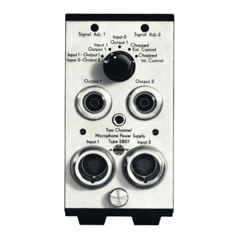
FRONT PANEL
Battery Voltage Indicator
The
"Battery
Voltage
Indicator"
shows
the
condition
of
the
batteries.
When
the
needle
is
in
the
green region
of
the
dial,
the
battery
voltage
is
4

within
the
operating range of 3.5 V
to
5 V. If
the
needle moves into
the
red
zone
the
voltage has fallen below
the
limits and
the
batteries should be
replaced. This indicator permits observation
of
battery degradation as it
occurs.
Output
Control Knob
This knob controls what appears
at
the
outputs
of
the
device.
In
the
"Off"
position there
is
no power
in
the unit and therefore no output.
In
the
l1position
the
signal from
"Input
1"
appears
at
"Output
1"
and
the
signal
from
"Input
2"
at
"Output
2".
In
the X,position the signal from
"Input
1"
appears
at
"Output
2"
and
the
signal from
"Input
2"
appears
at
"Output
1". This feature allows ease
in
making comparison measurements.
Outputs 1 and 2
These terminals accept the standard JP
0018
connector and carry one
or
the other of
the
two input signals depending on
the
setting
of
the
"Output
Control Knob".
Inputs 1 and 2
These terminals are the standard B & K microphone sockets accepting
the JP 0023 seven pin plug. They carry
the
ground, polarization voltage,
heater voltage {when present, see Section Rear Panel), etc., for powering
the
microphone {or accelerometer)
Type
2619 preamplifier. They also carry
the
signal from
the
transducer.
Thumb Screw {Polarization Voltage Selection)
This screw releases the.
bottom
plate
of
the
unit. When this plate
is
removed
the
printed circuit card
is
revealed. On this card
is
a small rotary
two position switch for selecting
the
polarization voltage desired. {Fig.2.2).
5

6
Voltage
Selector
Fig.2.2, Printed Circuit Card Indicating Voltage Selection Switch.

Right Side
Panel Screw
Battery
Chamber
Screw
Fig.2.3. Rear Panel
of
Type 2804.
REAR
PANEL
Battery Chamber Screw
This screw holds
the
top
plate on
the
unit. When it has been removed and
the
top
plate taken off,
the
battery
contact
plate
is
revealed. This
contact
plate
is
hinged and tilts back revealing
the
three
batteries. Batteries should
always be inserted with polarities as indicated
on
the
inside of
the
battery
chamber. (Fig.2.4).
7

Fig.2.4. Battery Chamber
of
the 2804.
Polarization Voltage
This terminal
is
a test
point
for
checking the polarization voltage. A high
impedance meter must
be
used
for
making this measurement.
Warning: The polarization voltage should
be
checked before
use
to
prevent accidental connection
of
200 V
to
a 28 V device. Connection
of
200 V
to
a
28
V device may destroy
it!
Right Side Panel Screw
This screw holds the
right
side panel
of
the instrument.
If
the panel
is
removed
it
reveals the adjustment potentiometers. Should adjustments be-
come necessary please consu
It
the Service Manual.
28
V DC Outlets
These
two
terminals accept coax connectors
JP
0012 and provide
28
V
DC
at 2 rnA
each
to
vibration pick-up preamplifiers.
or
any device
with
similar power requirements.
If
only
one
of
these terminals
is
used,
it
can
provide 4 rnA
of
28
V
DC
when no 2619 preamplifiers are connected
to
the
input
terminals.
8

6 V DC Input for 2619 Heating Element
If
the
heating
element
of
the
Type
2619
preamplifier
is
to
be used it
must
have 6 V
DC
power. Since
the
2804
does
not
produce
6 V
DC
it
must
be provided externally by means
of
a
battery
or
power
supply and may be
applied through these
two
terminals. These terminals are
connected
to
the
appropriate
pins
of
the
"Input"
terminals
and
accept
banana jack connect-
ors with ground going
to
the
right
hand
terminal
and
6 V
to
the
other.
(See
Fig.2.3).
2.2. INSTALLATION IN MODULE SYSTEM
The
2804
is
part
of
the
8 & K Module·System. This system
is
designed
for easy rack mounting of
instrument
combinations
so
that
entire
measure-
ment
systems may be conveniently assembled
in
the
same rack.
Fig.2.5.
The
8 & K Module System.
9

The system consists
of
a metal case
KK
0010
in
which
the
modules are
mounted and
of
either
a wooden case
KA
0020
into which
the
KK
0010
is
fitted if a portable system
is
desired
or
a pair
of
slotted metal flanges which
are screwed
to
the
sides
of
the
metal case
if
the
system
is
to
be used
in
a
standard
19"
equipment
rack. (The flanges are included with
the
KK
0010).
10
The
2804
is
mounted
in
the
KK
0010
in
the
following manner:
1.
Loosen
the
"Thumb
Screw" on
the
front
panel and remove
the
bottom
plate.
2.
Unscrew
the
feet
from
the
bottom
plate.
3. Using
the
screws which held
the
feet on, screw
the
bottom
plate
in
the
desired location
in
the
metal case (KK 0010).
4. Slide.
the
unit
on
to
the
bottom
plate and secure it by tightening
the
"Thumb
Screw".
Fig.2.6. Mounting
of
a Module in the Module System
Case.

3.
DESCRIPTION
The
2804
is
a battery driven transistorized power supply which uses a
40
kHz oscillator and transformer
to
step
the
3.5
V
to
5 V battery voltage
up
to
the
200 V polarization voltage required by many condenser micro-
phones.
The
stepped up voltage
is
half wave rectified and filtered
at
both
28
V and
200
V.
The 200 V provides
the
polarization voltage through a
dropping network where a switch (Fig.2.2) allows selection of two different
points on
the
network, one adjusted
to
200
V and
the
other
to
28
V.
The
voltage rectified
at
28
V goes directly
to
the
"28
V
DC
Outlets" and
to
the
biasing
of
the
microphone preamplifiers.
6V
DC
Input
Fig.3.
1.
Block Diagram
of
Type 2804.
11

4.
OTHER
INSTRUMENTS
AND
THE 2804
4.1. CONDENSER MICROPHONES
The B & K condenser microphones
with
accompanying Preamplifier
Type
2619
plug
directly
into
the
"Inputs"
of
the
2804
and
are
provided
with
all
the
voltages necessary
for
their
operation. Consult the appropriate
microphone
instruction
manual
for
polarization voltage requirements.
42.ACCELEROMETERS
The B & K accelerometers
with
accompanying preamplifier 2619 may
be
plugged
into
the
Inputs
of
the 2804,
or
they may derive 28 V power direct-
ly
from
the
"28
V DC
Outlets"
at the rear
of
the
unit.
(Fig.2.3).
See
appro-
priate
instruction
manual
for
exact requirements.
Fig.4.
1.
Adaptor
Type
ZR
0024.
4.3.
VIBRATION
PICK-UP PREAMPLIFIERS
Vibration
Pick-up Preamplifiers Type 2623 and 2625 may be powered
by
the
2804
directly
from
the
"28
V DC Outlets". Type 2625 may also
be
powered through the
"Input"
of
the 2804
by
use
of
Adaptor
ZR
0024.
Further
details are available
from
the B & K Main Catalogue and appropriate
instruction manuals.
12

5.
SPECIFICATIONS
Dimensions:
Weight
without
Battery:
Weight with Battery:
Battery Voltage:
Battery Life when Driving
2 Type 2619:
Polarization Voltage Output:
Polarization Voltage Stability:
28
V Outputs:
Temperature Range:
Maximum Humidity:
Noise and Ripple:
Attenuation:
Cross-Talk Attenuation:
Accessories Included:
Height: 132.6 mm (5.30")
Width: 61.3 mm
(2.45")
Depth: 200.0
mm
(8.00")
1
kg
(2.2 lb)
1.267
kg
(2.8 lb)
3.5 V
to
5 V
Approx.
40 hours
200 V
or
28 V
±2%
2
mA
each
or 4
mA
if
only one
is
used
oo
to
600C
(with
Special Batteries)
oo
to
400C
(with
Batteries Supplied)
-250
to
700C (Storage Conditions)
95% rei. (400C)
Gives no additional noise
on
output
of
Type 2619.
0 dB, both channels
Better than 100 dB
for
frequencies
be-
low
20kHz.
Better than 80 dB up
to
200kHz.
Three 1.5 V
Batteries-
Monozelle, IEC
R 20. 13


B &K INSTRUMENTS:
ACOUSTICAL
....
Condenser
Microphones
Piezo-Electric
Microphones
Microphone
Preamplifiers
Microphone
Calibration
Equip.
Sound
Level
Meters
(general
purpose-precision-
and impulse)
Standing
Wave
Apparatus
Tapping
Machines
Noise
Limit
Indicators
ELECTROACOUSTICAL.
...
Artificial
Ears
Artificial
Mouths
Artificial
Mastoids
Hearing
Aid
Test
Boxes
Telephone
Measuring
Equipment
Audiometer
Calibrators
Audio
Reproduction
Test
Equip.
STRAIN
....
Strain
Gauge
Apparatus
Multipoint
Panels
Automatic
Selectors
Balancing
Units
VIBRATION
....
Accelerometers
Accelerometer
Preamplifiers
Accelerometer
Calibrators
Vibration
Meters
Magnetic
Transducers
Capacitive Transducers
Vibration
Exciter
Controls
Vibration Programmers
Vibration Signal
Selectors
Mini-Shakers
Complex
Modulus
Apparatus
Stroboscopes
GENERATING
....
Beat Frequency
Oscillators
Random Noise Generators
Sine-Random Generators
MEASURING
....
Measuring
Amplifiers
Voltmeters
Deviation
Bridges
Megohmmeters
ANALYZING .
...
Band-Pass
Filter
Sets
Frequency
Spectrometers
Frequency Analyzers
Real-Time Analyzers
Slave Filters
Psophometer
Filters
Statistical Analyzers
RECORDING
....
Level Recorders
(strip-chart and polar)
Frequency Response
Tracers
Tape Recorders
EIFIUEL&
~\.Jj!ER
DK-2850
Nrerum, Denmark. Teleph.:
(01)
80
05
00.
Cable: BRUKJA, Copenhagen. Telex:
5316
Other manuals for 2804
1
Table of contents
Other BRUEL & KJAER Power Supply manuals