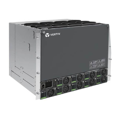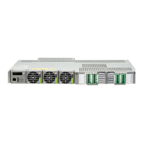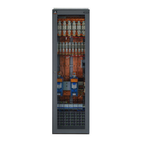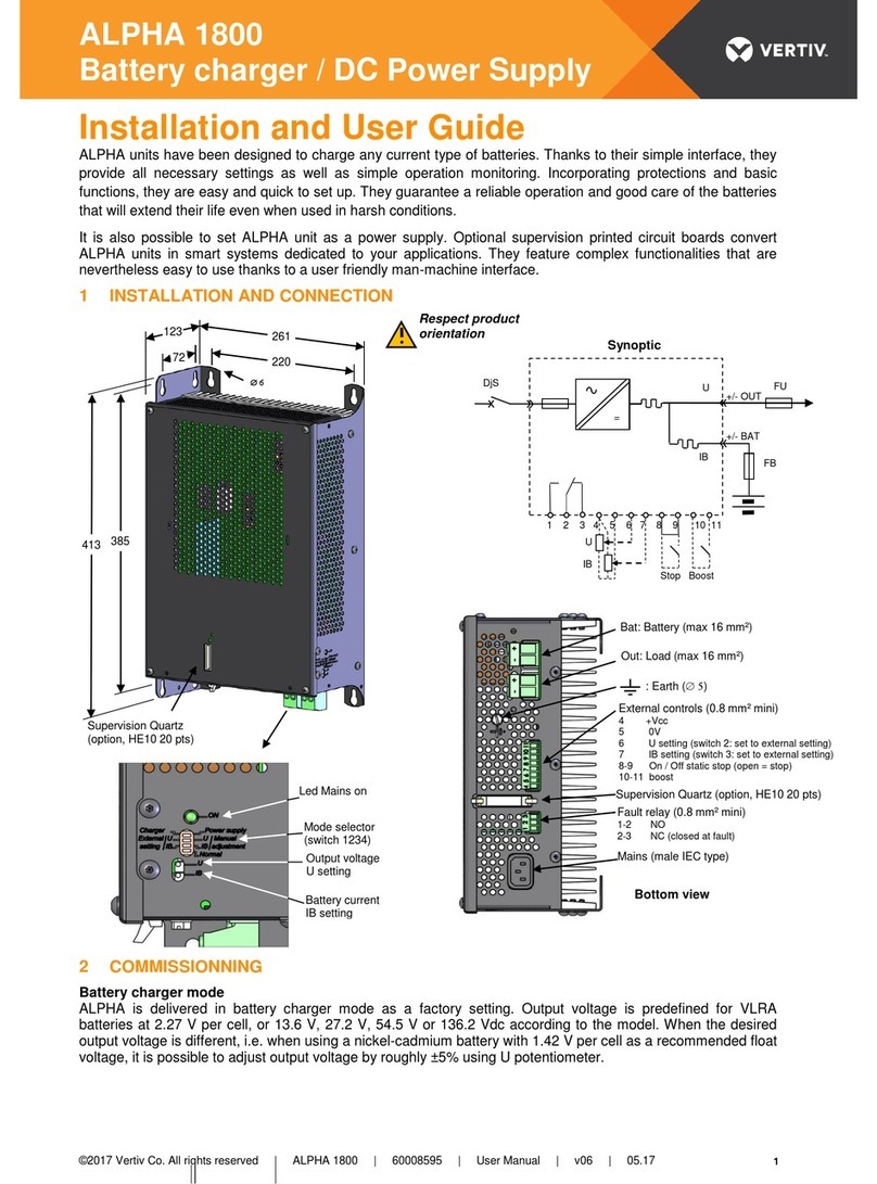
Vertiv™NetSure™-48 VDC Power System
System Application Guide
Spec. No: 582140001 Proprietary and Confidential © 2022 Vertiv Group Corp. SAG582140001
Model No: 801NLDB, 801NLEB, 801NL-BPage 6 Revision T, September 28, 2022
TABLE OF CONTENTS
SYSTEM OVERVIEW............................................................................................................................................................................................................. 1
MAIN COMPONENTS ILLUSTRATIONS..........................................................................................................................................................................8
582140001 Power Bays .................................................................................................................................................................................................8
582140001 Distribution Bays.......................................................................................................................................................................................9
582140001 Power Bays Monitor and Control Diagram.......................................................................................................................................10
582140001 Distribution Bays Monitor and Control Diagram.............................................................................................................................10
LIST DESCRIPTIONS ...........................................................................................................................................................................................................11
List 0A: 380/480VAC Plant Input Voltage......................................................................................................................................................................................11
List 0B: 208VAC Plant Input Voltage .................................................................................................................................................................................................11
List 04: Primary Power Bay (2 AC Input Feeds) ..........................................................................................................................................................................11
List 05: Primary Power Bay (12 or 24 AC Input Feeds) ..........................................................................................................................................................12
List 06: Primary Power Bay (6 AC Input Feeds).........................................................................................................................................................................12
List 12: Secondary Power Bay (2 AC Input Feeds) ....................................................................................................................................................................13
List 13: Secondary Power Bay (12 or 24 AC Input Feeds).....................................................................................................................................................14
List 14: Secondary Power Bay (6 AC Input Feeds)....................................................................................................................................................................14
List 16: Distribution Bay..............................................................................................................................................................................................................................15
List 21: Rectifier Module, 208V Input .................................................................................................................................................................................................15
List 22: Rectifier Module, 380/480V Input .....................................................................................................................................................................................16
List 24: Rectifier Module, 380/480V Input.....................................................................................................................................................................................16
List 50: Optional LMS Main CPU Circuit Card (Primary Power Bay).............................................................................................................................16
List 63: Optional LMS Expansion CPU Circuit Card (Secondary Power Bays) .......................................................................................................16
List 64: Interface Kit to a Spec. No. 582121900 Power System equipped with a DGU.......................................................................................16
List 65: Interface Kit to a Spec. No. 582121901 Power System equipped with an LMS1000 ..........................................................................17
List 66: Interface Kit to a Vortex Power System without a DGU or LMS1000 ........................................................................................................17
List 67: Interface Kit to a Model 1231H Legacy Power System with 1-8 Rectifiers ...............................................................................................17
List 70: Additional MCA Six (6) Output Form-C Relay Circuit Card..............................................................................................................................18
List 71: MCA I/O Circuit Card P/N 524550 .....................................................................................................................................................................................18
List 0C: 24 Position Bullet-Nose Circuit Breaker/Fuse Panel ............................................................................................................................................19
ACCESSORY DESCRIPTIONS .........................................................................................................................................................................................20
Seismic Anchor Kit, P/N 545387 ..............................................................................................................................................................................20
Seismic Anchor Isolation Kit, P/N 545388.............................................................................................................................................................20
Main Battery Termination Bars (MBTB’s) .............................................................................................................................................................20
Distribution Device and Load Lug Locations.......................................................................................................................................................20
Distribution Devices.................................................................................................................................................................................................... 24
218 Circuit Breaker Assemblies .............................................................................................................................................................................................................24
TPL Fuses and Fuseholder Assemblies............................................................................................................................................................................................28
Bullet Nose-Type Circuit Breakers and Bullet Nose-Type Fuseholders e/w TLS/TPS Fuses........................................................................31
Optional Bullet Nose-Type 10-Position GMT Fuse Module for List C...........................................................................................................................36
Replacement Alarm, Reference, and Control Fuses ........................................................................................................................................... 37
Fuseblock Located in Bay’s Left Center ..........................................................................................................................................................................................37
Input and Alarm Fuse on Optional Bullet Nose-Type 10-Position GMT Fuse Module, P/N 509128 ..........................................................38
Wiring Components..................................................................................................................................................................................................... 39
Load Distribution Wire Sizes and Lugs Selection (Distribution Bay)............................................................................................................................39
Power Bay DC Output Cable Sizes and Lugs Selection.........................................................................................................................................................43
Distribution Bay DC Input Cable Sizes and Lugs Selection.................................................................................................................................................45
Power Bay Frame Grounding Wire Sizes and Lugs Selection ............................................................................................................................................47
Distribution Bay Frame Grounding Wire Sizes and Lugs Selection................................................................................................................................48
AC Input (12 or 24 AC Input Feeds) Wire and Conduit Sizes, Branch Circuit Protection, and Lugs Selection Lists 5
and 13......................................................................................................................................................................................................................................................................49
AC Input (6 AC Input Feeds) Wire and Conduit Sizes, Branch Circuit Protection, and Lugs Selection Lists 6 and 14.................52
AC Input (2 AC Input Feeds) Wire and Conduit Sizes, Branch Circuit Protection, and Lugs Selection Lists 4 and 12................58
External Alarm, Reference, and Control Wire Sizes - Power Bays....................................................................................................................................61
Optional Battery Charge Temperature Compensation Probe for Digital Compensation ......................................................................... 62
Replacement/Additional MCA Network Cable..................................................................................................................................................... 63
Replacement/Additional LMS Network Cable ..................................................................................................................................................... 63
Replacement Modules and Circuit Cards..............................................................................................................................................................64
