Metallkraft MBSM Series User manual
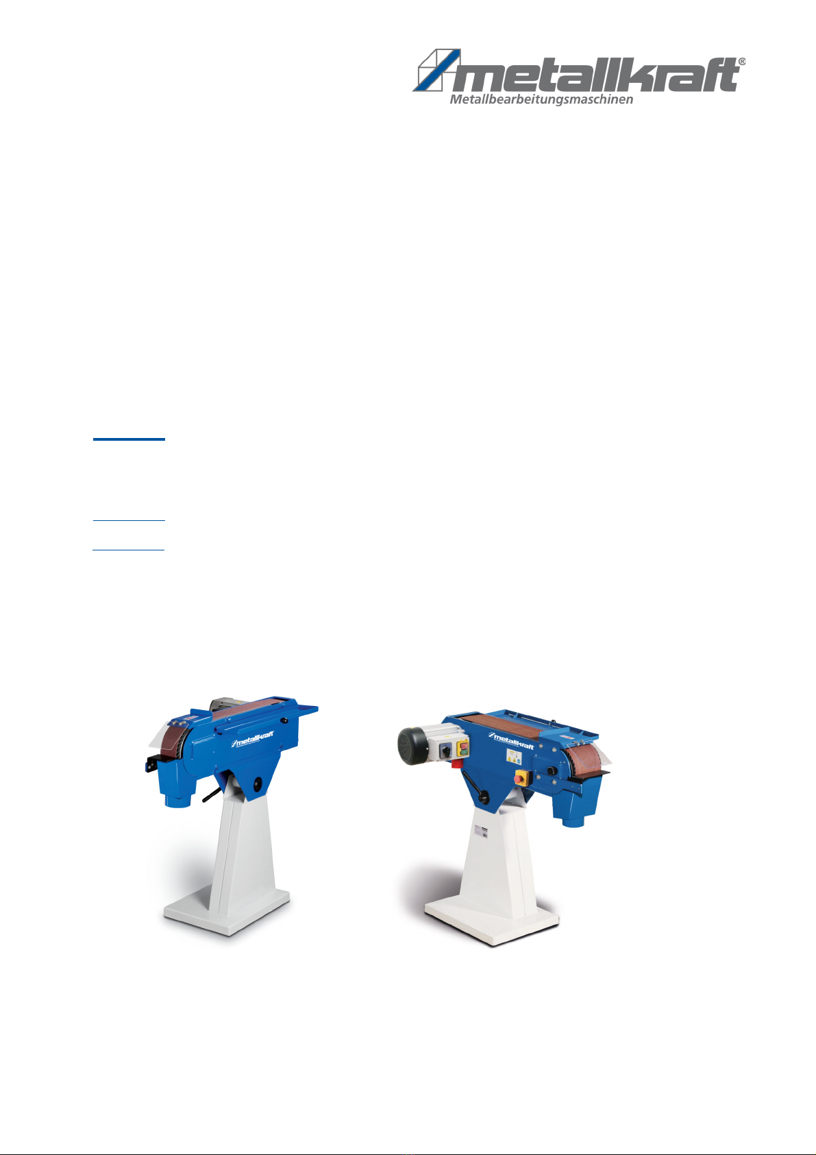
MBSM 150-200-2
Operating Instruction
MBSM 75-200-2
MBSM - SERIES
Metal-belt sander
MBSM 150-200-2
MBSM 75-200-2

2 MBSM 75-200-2 | MBSM 150-200-2 | Version 2.05
Imprint
Product identification
Metallkraft
Metal- belt sander
Model Item number
MBSM 75-200-2 3922075
MBSM 150-200-2 3922150
Manufacturer
St rmer Maschinen GmbH
Dr.-Robert-Pfleger-Str. 26
D-96103 Hallstadt
Fax: 0049 (0) 951 96555 - 55
E-Mail: [email protected]
Internet: www.metallkraft.de
Indications regarding operating instructions
Original operating instructions
Edition: 13.09.2021
Version: 2.05
Language: English
Author: MS
Indications regarding the copyright
Copyright © 2021 St rmer Maschinen GmbH, Hall-
stadt,Germany.
The contents of these operating instructions is the sole
property of the company St rmer Maschinen GmbH.
Passing on as well as copying of this document, the use
and distribution of its content are prohibited if not explic-
itly permitted. Contraventions are liable to compensa-
tion.
Subject to technical modifications and error.
Contents
1 Introduction ............................................. 3
1.1 Copyright ............................................................ 3
1.2 Costumer service................................................ 3
1.3 Limitation of liability............................................. 3
2 Safety ....................................................... 4
2.1 Symbol explanation ............................................ 4
2.2 Obligations of the operating company ................ 4
2.3 Requirements to staff.......................................... 5
2.4 Personal protective equipment ........................... 5
2.5 Safety devices .................................................... 6
2.6 Safety identifications on the Metal- belt sander.. 6
2.7 Additional safety regulations............................... 7
2.8 Residual risk ....................................................... 7
3 Intended use ............................................ 7
4 Technica Data......................................... 8
4.1 Table................................................................... 8
4.2 Noise level .......................................................... 8
4.3 Type plate........................................................... 8
5 Transport and packaging ....................... 8
5.1 Delivery and Transport ....................................... 8
5.2 Packaging........................................................... 9
6 Description of the device ....................... 9
6.1 Illustration ........................................................... 9
6.2 Optional accessory ........................................... 10
7 Settings .................................................. 10
7.1 Sanding belt change......................................... 10
7.2 Sanding belt run................................................ 10
8 Operation of the machine..................... 11
8.1 General informations ........................................ 11
8.2 Surface-grinding on the sanding belt................ 11
8.3 Grinding on the workpiece support................... 11
8.4 Connection for connecting of an extraction
system ............................................................. 11
9 Notes for the grinding process............ 11
10 C eaning, maintenance and service .. 12
10.1 Cleaning......................................................... 12
10.2 Maintenance .................................................. 12
10.3 Service........................................................... 12
10.4 Storage .......................................................... 12
11 Disturbances, possib e causes and
measures ............................................. 12
12 Disposa , recyc ing of used
devices ................................................. 13
12.1 Decommission ............................................... 13
12.2 Disposal of electrical devices......................... 13
12.3 Disposal of lubricants..................................... 14
12.4 Disposal via municipal collecting points......... 14
13 Spare parts .......................................... 14
13.1 Spare parts order........................................... 14
13.2 Spare parts drawings..................................... 15
13.3 Parts list ........................................................ 16
14 Circuit diagram ................................... 19
15 EC-Dec aration of conformity ............ 20
16 Notes .................................................... 21

Introduction
MBSM 75-200-2 | MBSM 150-200-2 | Version 2.05 3
1 Introduction
With the purchase of the device of METALLKRAFT you
have made a good choice.
Thorough y read the operating instructions before
commissio-ning the machine.
It informs you about the proper commissioning, the in-
tended use as well as the safe and efficient operation
and maintenance of your device.
The operating instructions are part of the device. It must
always be stored at the place of use of the device. In ad-
dition, the local accident prevention regulations and ge-
neral safety regulations apply to the area of application
of the device.
The illustrations in these operating instructions serve the
general comprehension and may deviate from the ac-
tual type.
The term "machine" replaces the usual trade name of the
device to which these operating instructions refer.
1.1 Copyright
The contents of these instructions are copyright. Their
application is admissible in the frame the device utilisa-
tion. An application beyond the described application is
not allowed without written approval of the manufac-
turer. For the protection of our products, we shall regis-
ter trademark, patent and design rights, as this is possi-
ble in individual cases. We strongly oppose any infringe-
ment of our intellectual property.
1.2 Costumer service
Please contact your dealer if you have any questions
about your machine or technical information. There you
will be happy to help with expert advice and information.
Germany:
St rmer Maschinen GmbH
Dr.-Robert-Pfleger-Str. 26
D-96103 Hallstadt
Repair-Service:
Fax: 0049 (0) 951 96555-111
E-Mail: [email protected]
Internet: www.metallkraft.de
Spare part orders:
Fax: 0049 (0) 951 96555-119
E-Mail: [email protected]
We are always interested in valuable experience and
knowledge gained from using the application-which then
could be shared and be valuable to develop our products
even further.
1.3 Limitation of iabi ity
All information and notes in these operating instructions
were summarized taking the applicable standards and
rules, the state-of-the-art and our long-term knowledge
and experiences into consideration.
In the following cases the manufacturer is not liable for
damages:
- Non-observance of the operating instructions,
- Inappropriate use,
- Use of untrained staff,
- Unauthorized modifications,
- Technical changes,
- Use of not allowed spare parts.
The actual scope of delivery may deviate from the ex-
planations and presentations described here in case of
special models, when using additional ordering options
or due to latest technical modifications.
The obligations agreed in the delivery contract, the gen-
eral terms and conditions as well as the delivery conditi-
ons of the manufacturer and the legal regulations at the
time of the conclusion of the contract are applicable.

4 MBSM 75-200-2 | MBSM 150-200-2 | Version 2.05
Safety
2 Safety
This paragraph will give you an overview of all important
safety packages for the protection of persons as well as
for the safe and undisturbed operation. Other taskba-sed
safety notes are included in the individual chapters.
2.1 Symbo exp anation
Safety instructions
The safety notes in these operating instructions are high-
lighted by symbols. The safety notes are intro-duced by
signal words which express the concern of the risk.
Tips and recommendations
It is necessary to observe the safety notes quoted in
these operating instructions in order to reduce the risks
for personal injuries and damages to property.
2.2 Ob igations of the operating com-
pany
The operating company is the person who operates the
machine for business or commercial reasons by herself,
or leaves it to a third party for use or application, and who
bears the legal product responsibility for the pro-tection
of the user, the staff or for third parties.
Ob igations of the operating company:
If the machine is used for commercial purposes, the op-
erating company must comply with the legal working
safety regulations. Therefore, the safety notes in this op-
erating manual, as well as the safety, accident preven-
tion and environment protection regulations applying for
the area of application of the machine must be met. The
following applies in particular:
- The operating company must be informed about
the applying industrial safety regulations and fur-
ther analyse hazards resulting from the special
working conditions at the place of use the ma-
chine. She must implement these in form of oper-
ating manuals for the operation the machine.
- During the entire lifetime of the machine, the oper-
ating company must verify whether the operating
manuals prepared by her correspond to the cur-
rent status of the regulations, and must adapt
these if necessary.
- The operating company must unambiguously reg-
ulate and determine the responsibilities for instal-
lation, operation, troubleshooting, maintenance
and cleaning.
- The operating company must ensure that all per-
sons who work with the machine, have read and
understood this manual. Furthermore she must in-
struct the staff in regular intervals and inform them
about the hazards.
- The operator must provide the necessary protec-
tive equipment to the staff and order the use of the
necessary protective equipment in a binding way.
DANGER!
This combination of symbol and signal words indi-
cate an imminently dangerous situation which may
lead to death or severe injuries if they are not avoi-
ded.
WARNING!
This combination of symbol and signal words indi-
cate a possibly dangerous situation which may lead
to death or severe injuries if they are not avoided.
CAUTION!
This combination of symbol and signal words indi-
cate a possibly dangerous situation which may lead
to minor or light injuries if they are not avoided.
ATTENTION!
This combination of symbol and signal word indi-
cates a potentially hazardous situation which, if not
avoided, could result in property damage and envi-
ronmental damage.
NOTE!
This combination of symbol and signal words indi-
cate a possibly dangerous situation which may lead
to property and environmental damages if they are
not avoided.
Tips and recommendations
This symbol highlights useful tips and recommenda-
tions as well as information for an efficient and trou-
ble-free operation.

Safety
MBSM 75-200-2 | MBSM 150-200-2 | Version 2.05 5
Furthermore the operating company is responsible to
keep the machine always in a technically flawless state.
Thus, the following applies:
- The operator must ensure that the maintenance in-
tervals described in this manual are kept.
- The operator must have all safety devices checked
regularly for their good working order and their in-
tegrity.
2.3 Requirements to staff
The different tasks described in this manual represent
different requirements to the qualification of the persons
entrusted with these tasks.
Only persons reliable working procedures can be ex-
pected from, are allowed to perform all works. Persons the
responsiveness of which is affected by e. g. drugs, alcohol
or medication, are not allowed to work with the machine.
The qualifications of the personnel for the different tasks
are mentioned below:
Operator:
The operator is instructed by the operating company about
the assigned tasks and possible risks in case of improper
behavior. Any tasks which need to be per-formed beyond
the operation in the standard mode must only be per-
formed by the operator if it is indicated in these instructions
and if the operating company ex-pressively commissioned
the operator.
E ectrica y qua ified person:
Electrically qualified person is due to their professional
training, knowledge and experience as well as knowl-edge
of the relevant standards and regulations, in a po-sition to
carry out work on the electrical systems and to inde-
pendently recognize and avoid possible dangers.
Qua ified personne :
Due to their professional training, knowledge and expe-ri-
ence as well as their knowledge of relevant regulations the
specialist staff is able to perform the assigned tasks and to
recognize and avoid any possible dangers them-selves.
Manufacturer:
Certain works may only be performed by specialist per-
sonnel of the manufacturer. Other personnel is not au-
thorized to perform these works. Please contact our cus-
tomer service for the execution of all arising work.
2.4 Persona protective equipment
The personal protective equipment serves to protect per-
sons against impairments of safety and health while
working. The staff member has to wear personal protec-
tive equipment while performing different tasks on and
with the machine which are indicated in the individual
paragraphs of these instructions.
The personal protective equipment is explained in the
following paragraph:
WARNING!
Danger in case of insufficient qua i-
fication of the staff!
Insufficiently qualified persons cannot estimate the
risks while using the vacuum cleaner and expose
themselves and others to the danger of severe or
lethal injuries.
- Have all works only performed by qualified per-
sons.
- Keep insufficiently qualified persons out of the work-
ing area.
Eye Protection
The Eye protection protects the eyes from flying
parts and liquid splashes.
Ear protection
The Hearing protection protects ears from hearing
damage caused by noise.
Head protection
The industrial helmet protects the head against fall-
ing objects and knocking against fixed objects.
Protective g oves
The protective gloves serve to protect the hands
against sharp components as well as against fric-
tion, abrasions or deep injuries.
Safety boots
Safety boots protect the feet from being crushed, fall-
ing parts and slipping over on slippery ground.
Protective c othes
Protective clothes are made of a tightly fitted fabric
without the protruding parts of low tear strength.

6 MBSM 75-200-2 | MBSM 150-200-2 | Version 2.05
Safety
2.5 Safety devices
To protect against flying sparks, a protective screen is at-
tached to the housing above the contact wheel. The on-
off switch unit is combined with an emergency stop
switch.
When the machine is running, protective covers and
guards must never be opened or removed.
EMERGENCY STOP - Button
Press the emergency stop button (Fig. 1) and the device
will stop immediately. The power supply is switched off
or the drives are mechanically disconnected. After the
emergency stop button has been pressed, it must be un-
locked by turning so that the machine can be switched
on again.
Fig. 1: EMERGENCY-STOP-Button
2.6 Safety identifications on the Meta -
be t sander
There are safety markings and instructions attached to
the metal- belt sander (Fig. 2) which must be observed
and followed.
Fig. 2: Safety lables
1 Danger high voltage | 2 Warning about rotating machine parts,
entanglement hazard | 3 Pull out the mains plug ! | 4 Wear ear
protection! |
5 wear safety glasses ! | 6 Read operating manual!
The safety markings and instructions attached to the
workshop press must not be removed. Damaged or
missing safety markings can lead to malfunctions, per-
sonal injury and material damage. They have to be re-
placed immediately.
If the safety markings are not immediately recognizable
and comprehensible, the workshop press must be taken
out of operation until new safety markings have been af-
fixed.
- Before switching on the machine, check the correct
picking up of the workpiece!
- When working with the machine, never put your
hands near rotating parts!
- Do not remove the sharp-edged chips by hand;
Use hand brushes or chip hooks!
- Use the guards and fasten them securely. Never
work without guards and get them working. Check
the functionality before starting with the work.
WARNING!
Danger to ife due to non-functioning safety
devices!
In case of dysfunctional or overridden safety devices
there is a danger of getting serious injuries or even
danger to life.
- Before starting work, check that all safety equip-
ment is in place and correctly installed.
- Never override or bypass safety devices.
- Ensure that all safety devices are always accessi-
ble.
WARNING!
Danger to ife due to unintentiona restart!
In case of unintentional restart there is a danger of
getting serious injuries or even danger to life.
- Before restarting, make sure that the cause of the
emergency stop has been remedied and all safety
devices are installed and functioning.
- Only unlock the emergency stop button when there
is no longer any danger.
NOTE!
The machines are designed to meet the general
safety requirements. Please always observe the rele-
vant accident prevention regulations. In case of
doubt, ask the supervisor.
ATTENTION!
Before starting, using, servicing or otherwise inter-
vening on the machine, read the instructions for use
and maintenance carefully. Handling and working
with the machine is only permitted for persons who
are familiar with the handling and operation of the
machine.
23
4
1
56

Intended use
MBSM 75-200-2 | MBSM 150-200-2 | Version 2.05 7
- Keep the machine and its working environment al-
ways clean. Ensure adequate lighting.
- In principle, secure your workpiece when working
with suitable clamping devices. Make sure there is
sufficient support surface.
- The machine may not be modified in its design and
may not be used for purposes other than those
provided by the manufacturer.
- Never work under the influence of concentration
disorders diseases, fatigue, drugs, alcohol or
drugs.
- Remove tool wrench and other loose parts from the
machine after installation or repair before turning
on.
- Observe all safety and hazard warnings on the ma-
chine and keep them in perfect readable condition.
- Keep children and persons unfamiliar with the ma-
chine away from your work environment, machine
and tools.
- The machine may only be used, equipped and
maintained by persons who are familiar with it and
have been informed about the dangers.
- During maintenance, armament and maintenance
work, always switch off the machine! In addition,
disconnect the power plug or disconnect the ma-
chine from the power supply!
- Do not pull on the power cord to pull the plug out of
the socket. Protect the cable from heat, oil and
sharp edges.
- Make sure that the main switch is in the "OFF" po-
sition when connecting the device to the power
supply to prevent it from switching on accidentally.
- Wear tight-fitting work clothes, safety glasses,
safety shoes and a hearing protection. Tie your
long hair together. When working, do not wear
watches, straps, chains, rings or gloves (rotating
parts!).
- Eliminate disruptions that affect safety immedi-
ately.
- Never leave the machine unattended in operation
and remain with the machine until the tool is com-
pletely stopped. Then remove the mains plug to
protect against unintentional switching on.
- Protect the machine from wet (short circuit hazard).
- Never use power tools and machines near flamma-
ble liquids and gases (risk of explosion!).
- Before each use of the machine, make sure that no
parts are damaged. Damaged parts must be re-
placed immediately to avoid any danger!
- Do not overload the machine! You work better and
safer in the specified performance range. Use the
right tool! Make sure that the tools are not dull or
damaged.
- Only use original spare parts and accessories in or-
der to avoid possible danger and risks of accident.
2.7 Additiona safety regu ations
- The workpiece may only be brought into contact
with it after the grinding belt has been switched on.
- Keep your hands away from rotating parts.
- This machine is not suitable for wet grinding. Never
use water on the workpiece surface or on the sand-
ing belt.
2.8 Residua risk
Even if all safety regulations are followed and the ma-
chine is used correctly, there are still residual risks listed
below:
- Touching rotating parts or tools.
- Breakage / tear of the abrasives.
- Injuries due to flying workpieces or parts of work-
pieces.
- Fire hazard with insufficient ventilation of the en-
gine.
- Touching of live parts.
- Impairment of hearing during prolonged work with-
out hearing protection.
3 Intended use
The belt sander must be mounted according to the in-
structions. Only the parts supplied may be used. The belt
grinder is designed for grinding angular metal and metal
- like workpieces.
The machine is universally applicable for schools, handi-
craft enterprises, workshops and for the do-it-your-
selfers.
Proper use also includes compliance with all information
in this manual. Any use beyond the intended use or oth-
erwise is considered misuse.
Improper use:
The machine must not be used for grinding combustible
materials (e.g. magnesium, wood or similar).
NOTE!
It should be noted that each machine has residual
risks. When carrying out all operations (even the sim-
plest ones), great care should be taken. Safe working
depends on you!
8 MBSM 75-200-2 | MBSM 150-200-2 | Version 2.05
Technica Data
4 Technica Data
4.1 Tab e
4.2 Noise eve
The noise level (sound pressure level) of this machine
may exceed 87 dB (A) at the workplace.
In this case, sound and hearing protection measures are
required and have to be used by the operator.
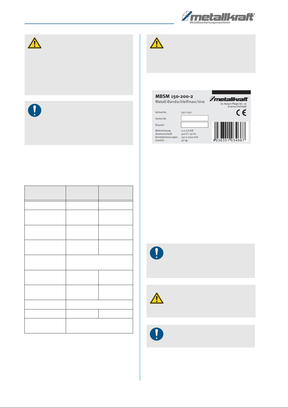
4.3 Type p ate
Fig. 3: Type plate MBSM 150-200-2
5 Transport and packaging
5.1 De ivery and Transport
Check the belt sander on delivery for any visible trans-
portation damage. If you notice any damage to the de-
vice please report this immediately to the carrier or
dealer.
Remove the machine from its packaging and remove all
protective films. Make sure that the machine is not set up
or put into operation in a damp or wet environment. The
humidity should not exceed 60% and the measured
room temperature should be between max. 0 ° C and 40
° C amount.
The machine may only be transported standing and with
the en
WARNING!
Danger in case of misuse!
Misuse of the device can lead to dangerous situa-
tions.
- Only operate the machine in the power range spec-
ified in the technical data.
- Never bypass or override the safety devices.
- Only operate the machine in a technically perfect
condition.
NOTE!
Unauthorized modifications to the machine or
improper use of the machine and disregard of safety
regulations or the operating instructions exclude lia-
bility of the manufacturer for resulting damage to per-
sons or objects and cause the warranty to lapse!
MBSM 75-
200-2
MBSM 150-
200-2
Engine power 1,5 / 2,2 kW 2,2 / 2,8 kW
Electrical
connection
400 Volt
~ 50 Hz
400 Volt
~ 50 Hz
Speed of sanding
belt
14,5 / 29 m/
sek.
14,5 / 29 m/
sek.
Dimensions 1070 x 340 x
950 mm
1070 x 415 x
950 mm
Contact wheel di-
mensions
Ø 200 mm
Sanding belt di-
mensions
2000 x 75
mm
2000 x 150
mm
Grinding width
max.
75 mm 150 mm
Suction socket 100 mm
Weight 72 kg 90 kg
sound pressure
level (dB)
87 dB(A)
WARNING!
It should be noted that the duration of the sound
exposure, the nature and condition of the work area
as well as other machines that are in operation at the
same time influence the noise level in the workplace.
NOTE!
For a safe stand, it is recommended that the machine
be fixed on a stable, flat surface (preferably con-
creted) using the holes provided in the machine base.
WARNING!
Danger to ife due to fa ing oad!
If the weight of the device is not observed during
transport, the machine may tip over or crash.
NOTE!
Protect the belt sander from moisture.

Description of the device
MBSM 75-200-2 | MBSM 150-200-2 | Version 2.05 9
Transport
Improper transport is prone to accidents and can cause
damage or malfunctions to the machine, for which we do
not provide any liability or guarantee.
Transport the scope of delivery secured against shifting
or tipping with a sufficiently dimensioned industrial truck
or a crane to the installation site.
General hazards during internal transport
Machines may only be transported by authorized and
qualified persons. Act responsibly when transporting and
always consider the consequences. Refrain from daring
and risky actions.
Inclines and slopes are particularly dangerous (e.g.
driveways, ramps and the like). If it is unavoidable to
drive on such passages, special care is required.
Before starting the transport, check the transport route
for possible hazards, bumps and imperfections as well
as sufficient strength and load-bearing capacity.
Hazardous areas, bumps and imperfections must be in-
spected prior to transport. The removal of hazardous
areas, bumps and obstructions at the time of transport by
other employees leads to considerable dangers.
Careful planning of internal transport is therefore essen-
tial.
Transport with a fork ift / pa et truck:
For shipping, the device is firmly mounted on a pallet so
that it can be transported with a forklift or a pallet truck.
5.2 Packaging
All used packaging materials and packaging aids are re-
cyclable and should be taken to a materials recycling de-
pot to be disposed of.
The delivery packaging is made of cardboard, so please
dispose carefully by having it chopped up and given to
the recycling collection
The film is made of polyethylene (PE) and the cushioned
parts of polystyrene (PS). Deliver these substances to a
collection point for recyclable materials or to the compe-
tent waste disposal company.
6 Description of the device
6.1 I ustration
I ustrations in this operating manua serve the gen-
era under-standing and may deviate from the actua
design.
Fig. 4: Description of the device
WARNING!
Serious to fatal injuries from falling over and fall
down of machine parts from forklifts, pallet trucks or
transport vehicles. Observe the instructions and
information on the transport box.
Note the total weight of the machine. The weight of
the machine is given in the "Technical data" of the
machine. When the machine is unpacked, the weight
of the machine can also be read on the nameplate.
Only use means of transport and load attachment
means that can take the total weight of the machine.
WARNING!
Serious to fatal injuries due to damaged or insuffi-
ciently stable lifting equipment and load attachment
devices that tear under load. Check the lifting gear
and load attachment devices for sufficient load-bea-
ring capacity and perfect condition.
Observe the accident prevention regulations of the
professional association responsible for your com-
pany or other supervisory authorities.
Fix the loads carefully.
WARNING DANGER OF TIPPING
OVER
The machine may not be lifted more than 2cm unse-
cured.
Employees must be outside the danger zone, the
reach of the load.
Warn employees and make employees aware of the
risk.
3
2
9
8
6
7
5
1
4
10
10 MBSM 75-200-2 | MBSM 150-200-2 | Version 2.05
Settings
1 Machine foot
2 Interlock angle adjustment
3 Electric engine 400 V ~ 50 Hz
4 Switching box / ON-OFF-Switch
5 Cover level grinding surface hinged
6 Cover contact wheel with workpiece stop
7 Adjustment screw belt direction
8 Chips-Box with suction socket
9 Workpiece support adjustable
10 EMERGENCY-STOP-Button
6.2 Optiona accessory
We recommend only using high-quality original MET-
TALKRAFT accessories. Only with original accessories,
a flawless operation and optimal work results can be
guaranteed.
7 Settings
To achieve good machine performance and a long ser-
vice life, the site should meet the following criteria.
- The device may only be installed and operated in
dry, ventilated rooms.
- Avoid places near chips or dust generating ma-
chines.
- The place of installation must be vibration-free, i.e.
away from presses, planing machines, etc..
- Provide sufficient space for the performance of the
work of set up men, the operating personnel and
material transport.
- Also consider the accessibility for adjustment and
maintenance work.
- Ensure adequate lighting (minimum value: 300
lux).
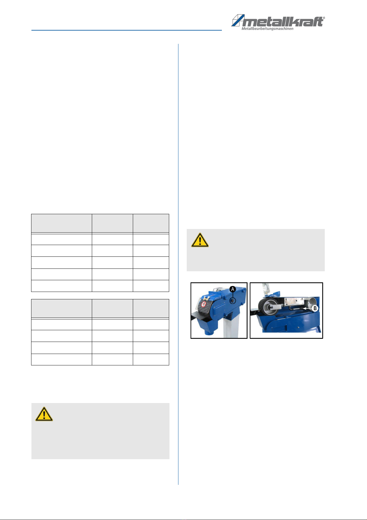
7.1 Sanding be t change
Unscrew the fastening screw (A) Fig. 5 and unfold the
side cover including the level grinding surfaces com-
pletely. Loosen the tension of the sanding belt by using
the tensioning lever (B) Fig.5. Carefully pull off the old
sanding belt. Tighten the new sanding belt and align it.
Finally, tighten the sanding belt over the tension lever
and close the side cover.
Fig. 5: Sanding belt change
7.2 Sanding be t run
The run of the sanding belt can be changed using the
sanding belt adjustment screw (Item 1, Figure 6). Check
the run of the sanding belt by gently moving it by hand.
To change the running direction of the sanding belt
loosen the hexagon head screw (item 2, Fig. 6) within
the adjusting screw (item 1). Then you can change the
tape running direction of the sanding belt by turning the
adjustment screw (item 1, Fig. 6) in a clockwise or coun-
terclockwise direction. Then move the sanding belt by
hand again and check the correct run. If necessary,
change the run again.
Sanding be ts for
extreme oad
MBSM 75-
200-2
MBSM
150-200-2
Sanding belt grain 24 3722022 3723022
Sanding belt grain 36 3722023 3723023
Sanding belt grain 40 3722024 3723024
Sanding belt grain 50 3722025 3723025
Sanding belt grain 60 3722026 3723026
Sanding be ts for
simp e use
MBSM 75-
200-2
MBSM
150-200-2
Sanding belt grain 40 3722004 3722014
Sanding belt grain 60 3722006 3722016
Sanding belt grain 80 3722008 3722018
Sanding belt grain 120
3722009 3722019
ATTENTION!
Before intervening on the machine, it must be discon-
nected from the power supply. Handling and working
with the machine is only permitted for persons who
are familiar with the handling and operation of the
machine.
ATTENTION!
When inserting the sanding belt, make sure that the
running direction of the arrow (see sanding belt inside)
matches the direction of the arrow on the housing.

Operation of the machine
MBSM 75-200-2 | MBSM 150-200-2 | Version 2.05 11
Fig. 6: Belt run adjustment
8 Operation of the machine
8.1 Genera informations
Before each start of work, the fo owing tests must be
carried out:
- Check all cables and plugs.
- Check that the workpiece supports are aligned and
tightened.
- Note that there are different grit sizes for different
jobs.
- Before starting the machine, make sure that the
sanding belt is free to rotate and that it is not
braked or blocked by any workpieces.
- Lubricate regularly according to item maintenance.
- Before commissioning, the center run of the
grinding be t must a ways be checked by man-
ua feed!
8.2 Surface-grinding on the sanding
be t
Check that the workpiece stop Pos. 7 in figure 4 is cor-
rectly mounted and tightened. Open the hinged cover
Pos.4 on figure 4. Switch on the belt sander and carefully
press the workpiece with both hands against the sanding
belt and the safety stop. For better material removal and
even belt wear, the workpiece can be easily moved back
and forth.
8.3 Grinding on the workpiece support
Hold the workpiece firmly with both hands. Grind internal
curves only on the front workpiece support.
8.4 Connection for connecting of an
extraction system
On the chip box Pos. 6 (Figure 4) and the back of the belt
grinder is a 100 mm Ø connecting piece for connection
to an extraction system.
9 Notes for the grinding pro-
cess
- When grinding, pay attention to the safety instruc-
tions and use the protective devices on the ma-
chine as well as your personal protective equip-
ment (protective goggles, ear protection, safety
shoes, etc.).
ATTENTION!
The grain size of the abrasives must be selected
according to the requirements.
NOTE!
After switching the belt speed, the run of the sanding
belt must be checked and, if necessary, readjusted.
ATTENTION!
Rotating parts! Get to work with reason. Pay atten-
tion to what you do. Pay special attention to the rotat-
ing parts. Wear tight-fitting clothing. Make sure that
hair or clothing is not caught by rotating parts! Wear
a hairnet. When working with the machine no jewelry
may be worn.
ATTENTION!
Risk of injury!
Flying chips and slinging away parts! Be sure to wear
safety glasses! Protect your eyes from flying chips
and other splinters.
1
2
ATTENTION!
Do not work with too much pressure, otherwise the
sanding belt wears too fast. Do not put your fingers in
contact with the sanding belt.
ATTENTION!
The edge of the workpiece supports must be posi-
tioned so that a distance of max. 1 mm is present to
prevent jamming of workpieces or fingers between
the table and the sanding belt.
12 MBSM 75-200-2 | MBSM 150-200-2 | Version 2.05
C eaning, maintenance and service
- Special reference to situations that may cause
damage to persons, the machine and / or the envi-
ronment or may lead to financial loss.
- Make sure that the gap between the work table and
the grinding wheel is not too large. Especially with
thin workpieces, there is a risk that the workpiece
will enter the gap!
- Since the machine does not have a clamping facil-
ity, it is important that your workpiece rest on the
worktable over the entire surface and be held tight!
- Make sure the abrasives are in good condition and
replace worn out abrasives in a timely manner.
Only with perfect tools you can achieve a good
grinding quality!
10 C eaning, maintenance and
service
Oil, grease and cleaning agents are hazardous to the en-
vironment and must not be disposed of in wastewater or
normal household waste.
10.1 C eaning
Basically, the machine should be cleaned after each use.
With the machine off, remove the chips and dust from
the cooling openings of the motor with a hand brush or
brush. Cleaning with compressed air is not allowed, as
the fine chips can easily fly into the eyes and cause inju-
ries.
For the disposa of the chips we refer to the oca
regu ations.
10.2 Maintenance
Empty the spark arrester regularly and check whether
the suction channel has to be cleaned. If the edges of the
contact wheel are rounded or the surface is damaged,
replace the contact wheel immediately. Replace the
graphite sanding pad on the plant table depending on
the degree of wear.
10.3 Service
As a result of wear and tear, it may happen that mainte-
nance work must be carried out on the machine.
10.4 Storage
Store the machine in a dry, clean, dust- and frost-free
environment. It must not be placed in a room with highly
oxidizing chemicals.
11 Disturbances, possib e
causes and measures
WARNING!
Always disconnect the machine from the power sup-
ply before starting any cleaning, maintenance or ser-
vicing work!
ATTENTION!
Risk of injury!
Do not remove the chips with bare hands. There is a
danger of cuts due to sharp-edged chips!
Dispose of these funds in an environmentally
friendly way. The cleaning cloths soaked in
oil, grease or detergent are easily
combustible. Collect the cleaning rags or
cleaning wool in a suitable, closed container
and dispose of them in an environmentally
friendly way - do not throw them in
household waste!
WARNING!
Repairs or maintenance work may only be carried
out by qualified and trained specialist personnel.
ATTENTION!
If one of the following errors occurs, stop working
with the machine immediately. Before you begin trou-
bleshooting, turn off the machine and unplug the
power cord. It could lead to serious injuries. All
repairs or replacement work may only be carried out
by qualified and trained specialist personnel.
NOTE!
If you can not solve the problems with your machine
yourself, then please contact your nearest
METALLKRAFT dealer. Please write down the follow-
ing information from the machine or the operating in-
structions in advance to help you with your problem in
the best possible way.
- Machine type
- Serial number of the machine
- Year of manufacture
- Error description in detail

Disposa , recyc ing of used devices
MBSM 75-200-2 | MBSM 150-200-2 | Version 2.05 13
12 Disposa , recyc ing of used
devices
Please take care in your own interest and in the interest of
the environment that all component parts of the machine
are only disposed of in the intended and permitted way.
Please note that electrical appliances contain a variety of
recyclable materials as well as environmentally harmful
components. Make sure that these components are dis-
posed of separately and properly. In case of doubt,
please contact your municipal waste disposal. If neces-
sary, the help of a specialized waste disposal company
can be used for the treatment.
12.1 Decommission
Immediately decommission disused machines in order to
avoid later misuse and endangering of the environ-ment
or personal safety.
- Unplug the power plug.
- Cut the connection cable.
- Remove all environmentally hazardous operating
materials from the old appliance.
- If applicable, remove batteries and rechargeable
batteries.
- If required, disassemble the machine into easy-to-
handle and usable components and parts.
- Dispose of machine components and operating
materials by the disposal channels provided.
12.2 Disposa of e ectrica devices
Please ensure that the electrical components are prop-erly
disposed of in accordance with legal regulations.
The device contains electrical and electronic compo-nents
and must not be disposed of as household waste. Accord-
ing to European Directive 2012/19 / EC on waste electrical
and electronic equipment and its transposition into na-
tional law, used electric tools and electrical machines must
be collected separately and recycled in an environmentally
sound manner.
As a machine operator, you should obtain information
about the authorized collection or disposal system that is
valid for you.
Please ensure that the batteries and / or rechargeable bat-
teries are properly disposed of in accordance with legal
regulations. Please throw only discharged batter-ies into
the collection boxes at retailers or municipal waste dis-
posal companies.
These components must be separated and properly dis-
posed of. In case of doubt, contact municipal waste man-
agement.
If necessary, the help of a specialized waste disposal
company can be used for the treatment.
Distur-
bances
Possib e
causes
Measures
Engine
does not
start.
Damaged on /
off switch.
Damaged on /
off switch line.
Relay dam-
aged.
Engine defec-
tive.
Fuses are de-
fective.
Have the machine
checked by an elec-
trician and have re-
placed the dam-
aged parts.
Machine
slows down
while work-
ing.
It is working
with too much
pressure.
Exert less pressure
on the workpiece.
Low ser-
vice life of
the abra-
sives.
Abrasive
(sanding belt or
disk) with too
fine grain.
Use a grinding
wheel with a
coarser grain size.
Bad grind-
ing pattern
Abrasive with
too coarse
grain size
Use a grinding
wheel with finer
grain size
Grinding
angle does
not fit
Adjusted an-
gles on the
work table or
on the stop
bracket do not
fit
Check the angle
and readjust if nec-
essary.
Grinding
wheel runs
optically
non-circular
Sanding belt
not properly at-
tached
Installing the grind-
ing wheel centrally
Sanding
belt runs off
the drive
pulleys
Sanding belt
not properly in-
stalled
Readjust the track
of the sanding belt.

14 MBSM 75-200-2 | MBSM 150-200-2 | Version 2.05
Spare parts
12.3 Disposa of ubricants
Spent coolant emulsions and oils should not be mixed
with each other as only non-mixed waste oils are recy-
clable without pretreatment.
The disposal instructions for the lubricants used are pro-
vided by the lubricant manufacturer. If necessary, ask for
the product-specific data sheets.
12.4 Disposa via municipa co ecting
points
Disposal of used electrical and electronic
equipment (Applicable in the countries of
the European Union and other European
countries with a separate collection system
for these appliances).
The symbol on the product or its packaging indicates that
this product should not be treated as normal household
waste, but must be returned to a collection point for the
recycling of electrical and electronic equipment.
By helping to properly dispose of this product, you are
protecting the environment and the health of others. En-
vironment and health are endangered by improper dis-
posal. Material recycling helps to reduce the consump-
tion of raw materials. For more information about
recycling this product, contact your local community, mu-
nicipal waste management, or the shop where you pur-
chased the product.
13 Spare parts
13.1 Spare parts order
Spare parts are available from authorised retailers or di-
rectly from the manufacturer.
Contact detai s:
Fax: 0049 (0) 951 96555-119
email: ersatzteile@stuermer-maschinen.de
Always quote the following key data with your spare
parts orders:
- Device type
- Article number
- Position number
- Year of manufacture
- Quantity
- Desired shipping type (post, freight, sea, air, express)
- Shipping address
Spare parts orders without the aforementioned data can-
not be taken into account. The supplier shall determine
the shipping type if no relevant data was provided. Infor-
mation about the device type, article number and year of
manufacture can be found on the type plate. The
type plate is mounted on the device.
Examp e
The sanding belt for the belt sander MBSM 75-200-2
must be ordered. The sanding belt has the number 57 in
the spare parts drawing 1.
By ordering spare parts, send a copy of the spare parts
drawing (1) with the marked part (sanding belt) and
marked position number (57) to the dealer or spare parts
department and provide the following information:
Device type:
Be t sander MBSM 75-200-2
Article number:
3922075
Drawing number:
1
Position number:
57
Artic e number of your device type:
Meta - be t sander
MBSM 75-200-2 3922075
MBSM 150-200-2 3922150
ATTENTION!
Please pay attention to an environmentally friendly
disposal of the used coolants and lubricants.
Observe the disposal informations of your municipal
disposal companies.
DANGER!
Risk of injury caused by the use of
incorrect spare parts!
The use of incorrect or faulty spare parts may cause
risks for operating staff and damage as well as
malfunctions.
- Exclusively genuine spare parts made by the manu-
facturer or spare parts authorized by the manufac-
turer shall be used.
- Always contact the manufacturer if you are unsure.
NOTE!
The manufacturer warranty shall be rendered void in
the event of a use of unauthorized spare parts.

Spare parts
MBSM 75-200-2 | MBSM 150-200-2 | Version 2.05 15
13.2 Spare parts drawings
In case of service, the following drawing shall help to identify the necessary spare parts. If necessary, send a copy of the
parts drawing with the marked components to your authorized dealer.
Fig. 7: Spare parts drawing 1 - MBSM 75-200-2 and MBSM 150-200-2

16 MBSM 75-200-2 | MBSM 150-200-2 | Version 2.05
Spare parts
13.3 Parts ist
MBSM 75-200-2 MBSM 150-200-2
Pos. Description Quan-
tity
Size Item number Item number
1 COUNTERSUNK SCREW ISO 7047 8 M4X6 0392207501 0392215001
2 COVER BELT ADJUSTMENT 1 0392207502 0392215002
3 WORKPIECE SUPPORT 1 0392207503 0392215003
4 HOLDER WORKPIECE SUPPORT 1 0392207504 0392215004
5 WASHER 2
Φ
8 0392207505 0392215006
6 COUNTERSUNK SCREW ISO 7991 2 M8X10 0392207506 0392215006
7 COUNTERSUNK SCREW ISO 7991 4 M8X16 0392207507 0392215007
8 U-METAL SHEET 1 0392207508 0392215008
9 MAIN GIRDER 1 0392207509 0392215009
10 CHIP BOX WITH CONNECTING
PIECE
1 0392207510 0392215010
11 CONTACT WHEEL 1 0392207511 0392215011
12 STAR GRIP - SCREW 3 0392207512 0392215012
13 SPRING 2 0392207513 0392215013
14 WASHER 2
Φ
8 0392207514 0392215014
15 WASHER 6
Φ
8 0392207515 0392215015
16 HEX-NUT ISO 7040 2 M8 0392207516 0392215016
17 HEX-NUT ISO 4032 2
M8
0392207517 0392215017
18 CONTACT WHEEL GUIDE 1 0392207518 0392215018
19 CYLINDRICAL PIN 1
Φ
6X50 0392207519 0392215019
20 HEXAGON SCREW 4 M8X25 0392207520 0392215020
21 LINEAR CAM 1 0392207521 0392215021
22 ADJUSTING SCREW 1 0392207522 0392215022
23 CYLINDER SCREW ISO 4762 1 M6X30 0392207523 0392215023
24 SPRING 1 0392207524 0392215024
25 SHAFTS - CIRCLIP 2
Φ
47 0392207525 0392215025
26 BEARING 2 204 0392207526 0392215026
27 CONTACT ROLLER - AXIS 1 0392207527 0392215027
28 WASHER 5
Φ
8 0392207528 0392215028
29 HEXAGON SCREW 2 M8X25 0392207529 0392215029
30 COUNTERSUNK SCREW ISO 7047 2 M4X10 0392207530 0392215030
31 WASHER 2 0392207531 0392215031
32 PROTECTIVE SCREEN 1 0392207532 0392215032

Spare parts
MBSM 75-200-2 | MBSM 150-200-2 | Version 2.05 17
33 FIXING ELEMENT 2 0392207533 0392215033
34 COUNTERSUNK SCREW 1 M6X50 0392207534 0392215034
35 WASHER 6
Φ
6 0392207535 0392215035
36 THREADED BOLTS 3 M8X12 0392207536 0392215036
37 COVER PLATE 1 0392207537 0392215037
38 LOCKING NUT 2 M6 0392207538 0392215038
39 NUT 2 M4 0392207539 0392215039
40 MOTOR 1 0392207540 0392215040
41 SCREW 4 M8x20 0392207541 0392215041
42 LEVER 1 0392207542 0392215042
43 COVER 1 0392207543 0392215043
44 SUPPORT PLATE 1 0392207544 0392215044
45 RIGHT COVER 1 0392207545 0392215045
46 LATERAL STOP 1 0392207546 0392215046
47 HANDLE 1 0392207547 0392215047
48 PIN 1 3X20 0392207548 0392215048
49 SPRING 1 0392207549 0392215049
50 LEVER 1 0392207550 0392215050
51 BASIS 1 0392207551 0392215051
52 WASHER 1 0392207552 0392215052
53 LOCKING BUTTON 1 0392207553 0392215053
54 LOCK SHAFT 1 0392207554 0392215054
55 SCREW 1 6X16 0392207555 0392215055
56 ALLEN SCREW 1 M5X20 0392207556 0392215056
57 GRINDING BELT 1 0392207557 0392215057
58 WASHER 1
Φ
32 0392207558 0392215058
59 DRIVE WHEEL 1 0392207559 0392215059
60 COUNTERSUNK SCREW 2
M8X20
0392207560 0392215060
61 PLASTIC DISC 2
Φ
8 0392207561 0392215061
62 HEXAGON SCREW 2 M8X12 0392207562 0392215062
63 CONNECTOR 1 0392207563 0392215063
64 HANDLE 1 0392207564 0392215064
65 GRAPHITE SUPPORT 1 0392207565 0392215065
66 HINGE 4 0392207566 0392225066
MBSM 75-200-2 MBSM 150-200-2
Pos. Description Quan-
tity
Size Item number Item number

18 MBSM 75-200-2 | MBSM 150-200-2 | Version 2.05
Spare parts
67 COUNTERSUNK SCREW ISO 7047 16 M4X6 0392207567 0392215067
68 CUP SPRING 1 0392207568 0392215068
69 HEXAGON SCREW 1 6X12 0392207569 0392215069
70 REMOVABLE SHEET 1 0392207570 0392215070
71 ADJUSTABLE HANDLE 1 0392207571 0392215071
72 MONTING PLATE 1 0392207572 0392215072
73 SCREW 1 8X120 0392207573 0392215073
74 SWITCH 1 0392207574 0392215074
75 SCREW 4 6X12 0392207575 0392215075
76 WASHER 4
Φ
6 0392207576 0392215076
77 EMERGENCY STOP 1 0392207577 0392215077
78 SCREW 4 4x12 0392207578 0392215078
MBSM 75-200-2 MBSM 150-200-2
Pos. Description Quan-
tity
Size Item number Item number

Circuit diagram
MBSM 75-200-2 | MBSM 150-200-2 | Version 2.05 19
14 Circuit diagram
Fig.5: Circuit diagram MBSM 75-200-2 and MBSM 150-200-2
20 MBSM 75-200-2 | MBSM 150-200-2 | Version 2.05
EC-Dec aration of conformity
According to Machinery Directive 2006/42/EC Annex II 1.A
Manufacturer / distributor:
St rmer Maschinen GmbH
Dr.-Robert-Pfleger-Straße 26
D-96103 Hallstadt
hereby declares that the following product
Product Group:
Metallkraft® Metallbearbeitungsmaschinen
Machine type:
Metal- belt sander
Description of the machine*:
MBSM 75-200-2
MBSM 150-200-2
Item number*:
3922075
3922150
Seria number*:
____________________
Year of manufacture*:
20____
* fill in these fields using the information on the nameplate
corresponds to all the relevant provisions of the abovementioned Directive and other Directives applied (below) - includ-
ing their amendments valid at the time of the declaration.
Re evant EU Directives:
2014/30/EU EMC Directive
The fo owing harmonized standards have been app ied:
DIN EN ISO 12100:2010 Safety of machinery - General principles for design - Risk assessment and risk
reduction (ISO 12100:2010)
DIN EN 60204-1:2007-06 Safety of machinery - Electrical equipment of machines - Part 1: General
requirements
Responsib e for documentation:
Kilian St rmer, St rmer Maschinen GmbH,
Dr.-Robert-Pfleger-Str. 26, D-96103 Hallstadt
Hallstadt, den 15/04/2016
______________________
Kilian St rmer
Manager
15 EC-Dec aration of conformity
This manual suits for next models
3
Table of contents
Popular Sander manuals by other brands

Sparky Group
Sparky Group PMB 1200CE Original instructions

Florida Pneumatic
Florida Pneumatic Universal Tool UT8756-1 quick start guide

Oliver
Oliver 5370 owner's manual

Scheppach
Scheppach DS200 Translation of the original manual

Rupes
Rupes LH75P Operating and maintenance instructions

Fein
Fein CG13-150 instruction manual


