MetalMaster HP-63T User manual

www.machineryhouse.com.au
www.machineryhouse.co.nz
Electrohydraulic Press
OPERATION MANUAL
HP-63T, HP-100T, HP-150T
HP-200T, HP-300T

www.machineryhouse.com.au
www.machineryhouse.co.nz
Please read the OPERATING INSTRUCTION before using.
INDEX
1. Performance characteristics and application
2. Technical parameters
3. Application
4. Checking & Filling Hydraulic Oil
4. Operation & Controls
5. Spindle Nose
6. Raising & Lowering the Beam
7. Sliding Head Type
8. Troubleshooting & Specications
9. Care and Maintenance
8. Risk Assessment & Test Certicate

www.machineryhouse.com.au
www.machineryhouse.co.nz
Electric Hydraulic Press
1 Performance characteristics and application
Metalmaster Electric hydraulic press are a developed product based on the experi-
ences found in the manufacture of press brakes and other hydraulic machines. They
are formed with a frame, bench beam, bolt, table plates, high pressure hose, oil tanks,
electrical boxes, and pumping stations, etc. (See gure 1).
.Performance Characteristics
1. Metalmaster electric hydraulic presses utilizes a single acting cylinder and operate
through a manual selector valve to control the up and down stroke.
2. The main column is equipped with a table and beam that can be moved up and down
by using the stroke of the cylinder to set the distance between the sizing block and cylin-
der spindle nose. The special lifting chains can be used to adjust the table up and down
by using the cylinder. The table beam is them secured at the height with the 2 pins.
3. The pins are tted with safety clips to insure that the pins can not be withdrawn dur-
ing operation.
4. The electrical control system is equipped with an emergency stop button, which is
convenient located to allow for a quick response if an emergency occurs.
5. Metalmaster Hydraulic presses are designed to meet the safety standards. Modica-
tions to the machines should not be made and may void your warranty. Please read the
“Risk Assessment” sheet supplied with the machine before operating

www.machineryhouse.com.au
www.machineryhouse.co.nz
1. Main frame 2. Table Plate
3. Bench Beam 4. Pins
5. Pump 6. Lifting Tool
7. Control box 8. High Pressure Hose
9. Cylinder
Fig.1
1
2
3
4
67
8
9
5

www.machineryhouse.com.au
www.machineryhouse.co.nz
Application
1. Service Conditions:
Do not exceeding indoor ambient temperature higher than +40 ℃, or less than -10 ℃.
Voltage 415V ± 10%, frequency 50Hz.
2. Service Scope:
The machine is suitable for the machinery industry where processes such as a press-t, or demoli-
tion, correction and forming operations are required.
Variable hydraulic pump station allows for rapid descending, slow proceeding and rapid return, which
promotes efciency and energy savings.
3. Checking The Oil
Before operating the press remove the plastic seal under the oil ller cap
(Fig.3) so the tank can breathe.
Check the oil level by viewing the site glass (Fig.2)
4. Filling The Press With Oil
It is extremely important that new, clean, light hydraulic oil be used in this
press, Superdraulic 46 or an equivalent. It is strongly recommended that the
oil be ltered to remove any possible dirt. The piston should be in its maxi-
mum upper position when lling the reservoir. Fill the reservoir to the upper
level on the site glass. UNDER NO CIRCUMSTANCES USE OLD DIRTY OIL.
Fig.2
Fig.3

www.machineryhouse.com.au
www.machineryhouse.co.nz
Operations And Controls
The operator should acquaint themselves with the use of the following
controls:
1. Main isolating switch is situated on the back of the machine and must be
turned “ON”
2. On/Off control panel contains the start and stop buttons and emergency
stop. To operate the press the ON button is presses to start the pump.
Under an emergency or if the pump needs to be stopped the large red stop
button can be pressed. To unlock the emergency stop twist the red knob.
3. The handle attached to the operating valve is used to move the ram up
and down. The handle is spring loaded and returns to the neutral position
when released
The ram is a single speed ram but does reduce in speed under load
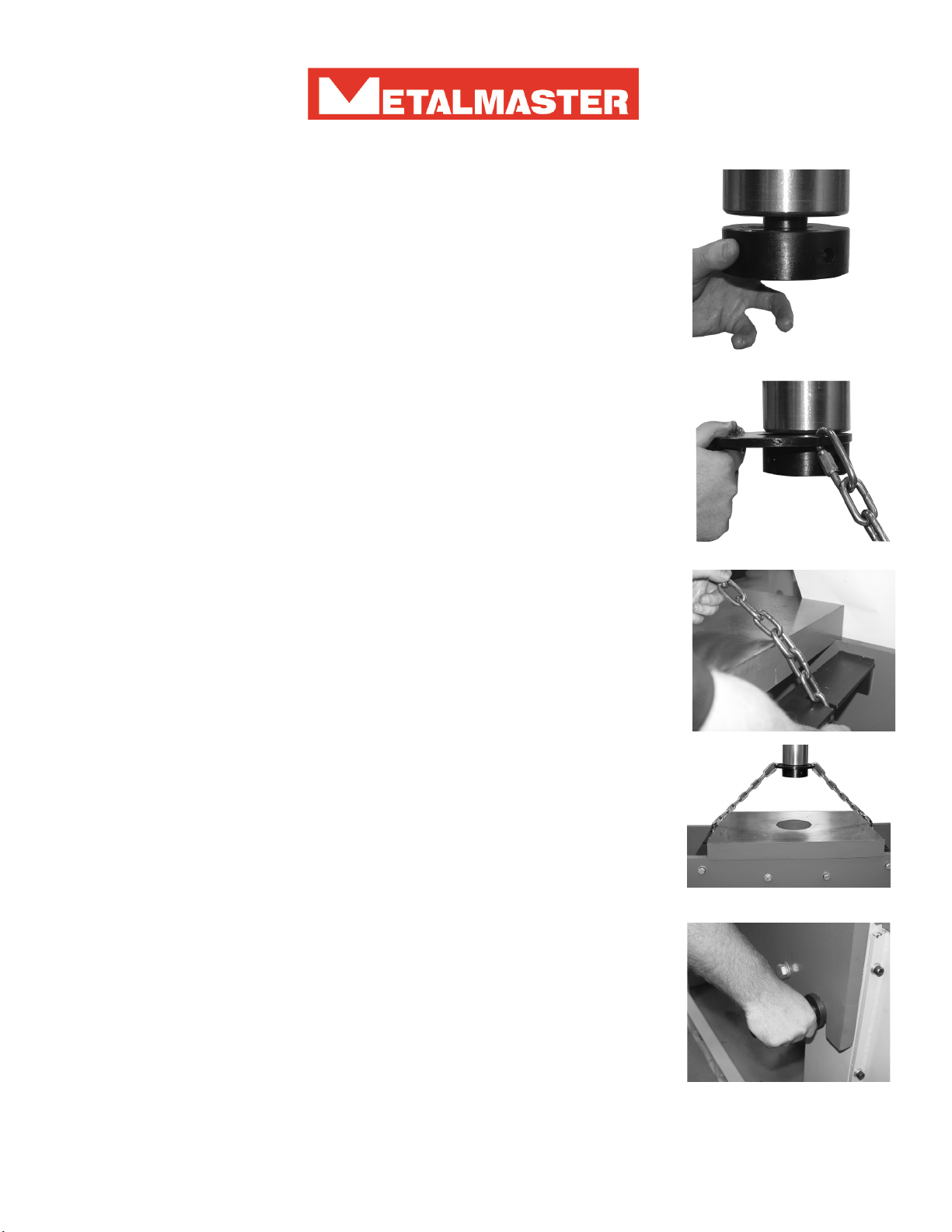
SPINDLE NOSE
1. The threaded spindle nose cap is designed for use with the chain retain-
ing plate used to raise and lower the beam.
X
2. The threaded nose cap must not be used as a ne adjuster and when
pressing and must at all times be adjusted so that there is no gap between
the cap and the spindle
www.machineryhouse.com.au
www.machineryhouse.co.nz
RAISING AND LOWERING THE BEAM
The operator should acquaint themselves with the method of lowering and
raising the beam before any attempt is made.
1. Loosen the spindle cap so that the chain retaining plate can be tted be-
tween the spindle and the spindle cap.
2. Mount the chain retaining plate between the spindle and spindle cap
and tighten the spindle cap making sure that the plate is mounted rm and
securely
3. The ends of the chain are then secured to the anchor points on the beam
making sure that the chain lengths are the same so that the beam will be
level when it is listed
4. With the ends of the chain are secured to the anchor points on the beam
slowly take the weight of the beam until the locating pins are loose.
5. With the pins now loose, remove the pins and raise or lower the beam
using the cylinder. When the beam is at the desired height locate place the
pins in the nearest pin hole.
Note! Never use ngers to locate or line up the holes

www.machineryhouse.com.au
www.machineryhouse.co.nz
SLIDING HEAD TYPE
METALMASTER also supply a range of hydraulic presses with a Sliding Work Head. These presses
allow for an expansion of many workshop applications. Once unlocked the head slides easily to the
left and to the right.
To move the head rst unlock the two clamps on the head, one
on the R/H side and one on the left. If there is no hand wheel the
head will slide very smoothly from side to side with no pressure on
the cylinder. (Fig 1.)
Fig. 1
Some larger models use a rack and pinion driven by a hand wheel
to move the head.(Fig.2)
Note! The head should always be secured before it is used
Fig. 2
www.machineryhouse.com.au
www.machineryhouse.co.nz
TROUBLE SHOOTING
FAULTS POSSIBLE REASON ACTION
Insufcient
Pressure
1. Gauge Failure
2. Blocked hole in either the
safety relieve valve, or poppet
valve
3. Loose or leaking joint or
damaged seal.
4. Blocked oil lter
1. Check pressure gauge and
repair or replace.
2. Check the seats on the
safety and poppet valve for
blockage
3. Tighten lacking joints and
replace damaged seals
4. Clean lter
Slow Flowing Tank
1. Low oil temperature
2. Low oil level causing oil
pump suction to be interrupted
3 Oil leaks restriking the ow.
1. Control the oil temperature
to 20 - 40 C
2. Top up oil level to operating
level
3. Check for leaks and tighten
joints and replace damaged
seals
For all other problems please contact the service department of the dealer you purchased the unit from or
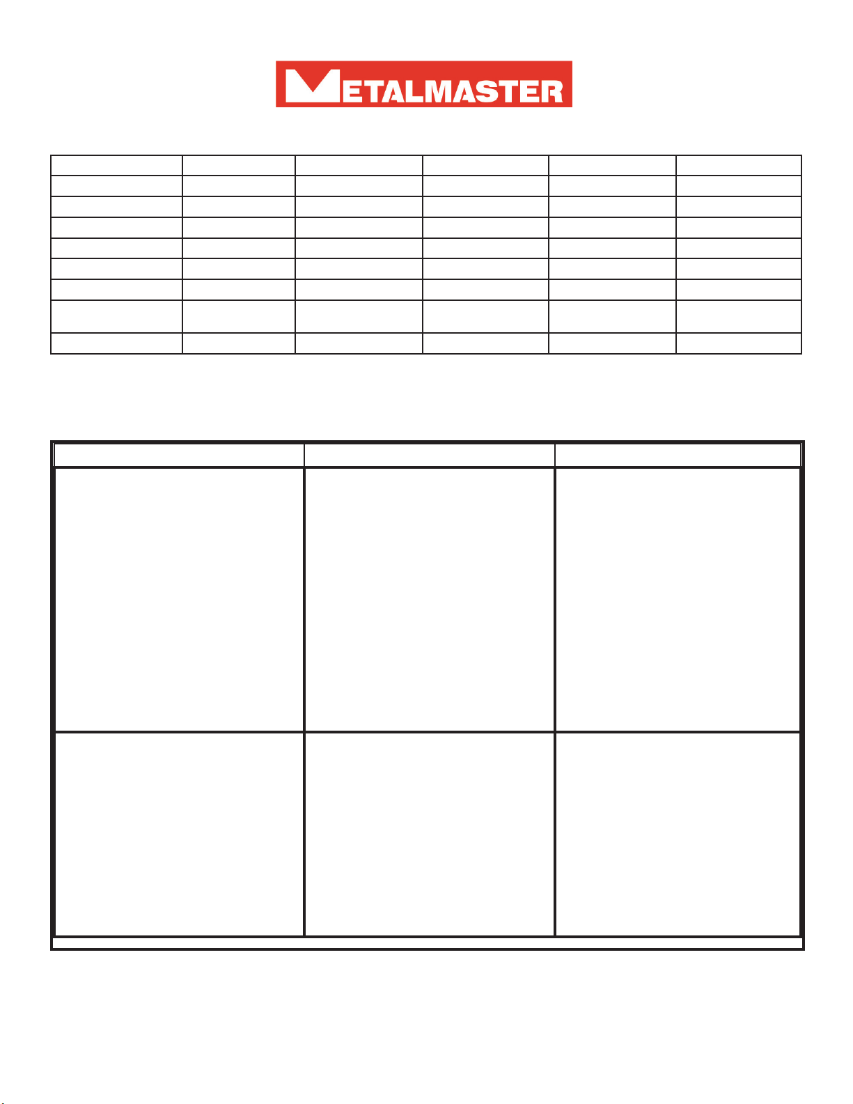
Specications
Model HP-63/HPM-63 HP-100T/HPM-100T HP-150T/HPM-150T HP-200T/HPM-200T HP-300T/HPM-300T
Capacity 60 Tonne 100 Tonne 150 Tonne 200 Tonne 300 Tonne
Piston Travel 325mm 363MM 390mm 420mm 380mm
Between Posts 895mm 1050mm 1100mm 1050mm 1200mm
Max Ram-Table 1000mm 1010mm 900mm 700mm 900mm
Voltage 415 415 415 415 415
Motor Power 4Kw 7.5Kw 7.5Kw 7.5Kw 22Kw
Dimensions LxWxH
(mm)
1900x930x2030 1970x1050s2230 2020x1120x2160 2280x1130x2530 2360x1220x2470
Weight (Kgs) 1060 1650 1950 2680 3700

www.machineryhouse.com.au
www.machineryhouse.co.nz
CARE AND MAINTENANCE
1. Before any maintenance is commenced switch the isolating switch to “OFF” If the power is sup-
plied through a switch and plug if possible remove the plug from the power point
2. Periodically check the joints and seals for leaks which could cause the machines performance to
be restricted.
Note ! Before examining the machine for leaks move the cylinder rod to the lowest position (except
when examine the cylinder)
3. Remove and wash the oil lter every six months
4. Used hydraulic oil must be ltered before. Replacement hydraulic oil with the same specication
every one to two years to insure normal running.
5. Keep the press surfaces clean an free of dirt and maintain the press regularly to insure the press
remains in good working order.
6. If the machine is not to be used for a long period of time, it should be cleaned and machine parts
should be coated with rust preventing oil. Remove the oil from the oil tank. Raise the cylinder rod to
the top position and place a piece of wood between the cylinder rod and the table to avoid the cylinder
rod dropping due to the dead weight of the cylinder..
7. The machine should be stored in a dry place with a temperature not lower than -15 C
8. Before any maintenance is commenced switch the isolating switch to “OFF” If the power is sup-
plied through a switch and plug if possible remove the plug from the power point
9. The pressure should never be adjusted unless under the supervision of the manufacturers staff
or service persons.
10. Always use the press and its hydraulic system as designed to be used by the manufacturer.
.

General Machinery Safety Instructions
1. Read the entire Manual before starting
machinery. Machinery may cause serious injury if
not correctly used.
2. Always use correct hearing protection when
operating machinery. Machinery noise may cause
permanent hearing damage.
3. Machinery must never be used when tired, or
under the influence of drugs or alcohol. When
running machinery you must be alert at all times.
4. Wear correct Clothing. At all times remove all loose
clothing, necklaces, rings, jewelry, etc. Long hair
must be contained in a hair net. Non-slip protective
footwear must be worn.
5. Always wear correct respirators around fumes
or dust when operating machinery. Machinery
fumes & dust can cause serious respiratory illness.
Dust extractors must be used where applicable.
6. Always wear correct safety glasses. When
machining you must use the correct eye protection
to prevent injuring your eyes.
7. Keep work clean and make sure you have good
lighting. Cluttered and dark shadows may cause
accidents.
8. Personnel must be properly trained or well
supervised when operating machinery. Make
sure you have clear and safe understanding of the
machine you are operating.
9. Keep children and visitors away. Make sure
children and visitors are at a safe distance for you
work area.
10. Keep your workshop childproof. Use padlocks,
Turn off master power switches and remove start
switch keys.
11. Never leave machine unattended. Turn power off
and wait till machine has come to a complete stop
before leaving the machine unattended.
12. Make a safe working environment. Do not use
machine in a damp, wet area, or where flammable
or noxious fumes may exist.
13. Disconnect main power before service
machine. Make sure power switch is in the off
position before re-connecting.
14. Use correct amperage extension cords.
Undersized extension cords overheat and lose
power. Replace extension cords if they become
damaged.
15. Keep machine well maintained. Keep blades
sharp and clean for best and safest performance.
Follow instructions when lubricating and changing
accessories.
16. Keep machine well guarded. Make sure guards
on machine are in place and are all working
correctly.
17. Do not overreach. Keep proper footing and
balance at all times.
18. Secure workpiece. Use clamps or a vice to
hold the workpiece where practical. Keeping the
workpiece secure will free up your hand to operate
the machine and will protect hand from injury.
19. Check machine over before operating. Check
machine for damaged parts, loose bolts, Keys and
wrenches left on machine and any other conditions
that may effect the machines operation. Repair and
replace damaged parts.
20. Use recommended accessories. Refer to
instruction manual or ask correct service officer
when using accessories. The use of improper
accessories may cause the risk of injury.
21. Do not force machinery. Work at the speed and
capacity at which the machine or accessory was
designed.
22. Use correct lifting practice. Always use the
correct lifting methods when using machinery.
Incorrect lifting methods can cause serious injury.
23. Lock mobile bases. Make sure any mobile bases
are locked before using machine.
24. Allergic reactions. Certain metal shavings and
cutting fluids may cause an ellergic reaction in
people and animals, especially when cutting as the
fumes can be inhaled. Make sure you know what
type of metal and cutting fluid you will be exposed
to and how to avoid contamination.
25. Call for help. If at any time you experience
difficulties, stop the machine and call you nearest
branch service department for help.
Machinery House
requires you to read this entire Manual before using this machine.

www.machineryhouse.com.au
www.machineryhouse.co.nz
TEST REPORT
Model Number .........................................
Serial Number .........................................
Date of Manufacturing ............/......./..................
Electrics qElectric Motor q
Hydraulics Pump qHydraulics q
The product has been checked and is manufactured in accordance with the code of stan-
dard for Hydraulic Presses
Examiner: .......................................................
Date: ........../............../..................
This manual suits for next models
4
Table of contents
Other MetalMaster Power Tools manuals


Popular Power Tools manuals by other brands


KRESS
KRESS 1-2+FIX instruction manual

Parkside
Parkside PSTK 800 A1 translation of original operation manual

Bosch
Bosch GNA 2,0 Professional Original instructions

Silverline
Silverline 633629 owner's manual

Powermate
Powermate Px P024-0098 instruction manual

Porter-Cable
Porter-Cable PCC650 instruction manual