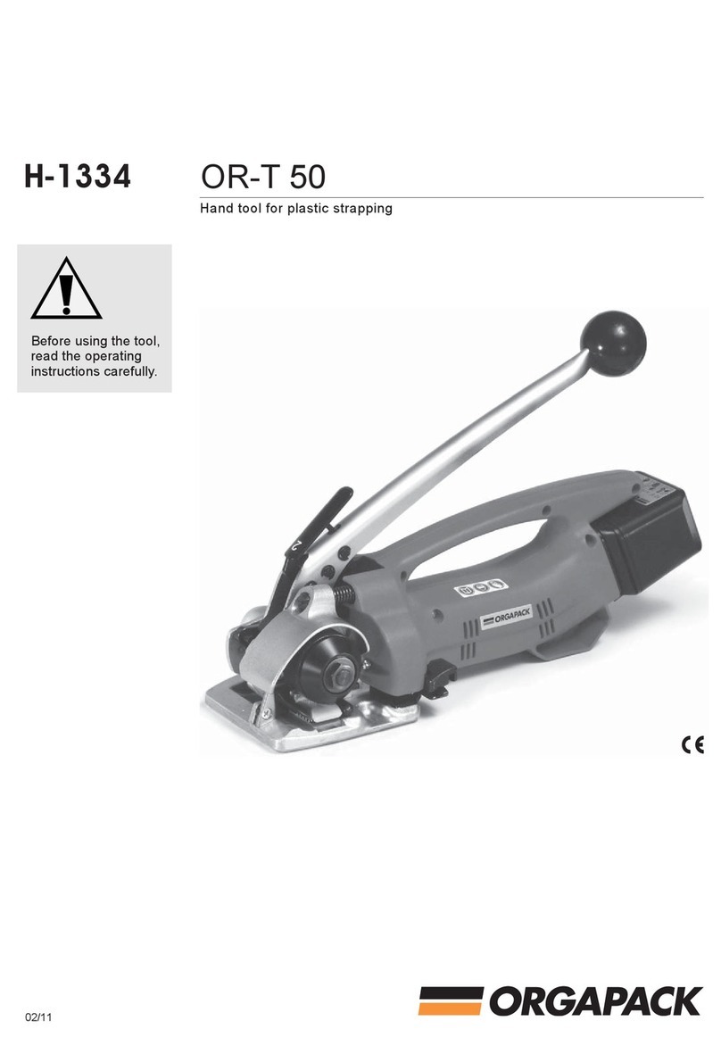
Orgapack OR-T 50 Quick guide

12.06/WE
Handgerät zum Umreifen mit Kunststoffband
Hand tool for plastic strapping
Appareil pour cerclage par bande plastique
Apparecchio per reggiare con reggetta di plastica
Ab Serie-Nr. 50/61650
From serie no 50/61650
A partir du no de série 50/61650
A partire dal no di serie 50/61650
OR-T 50
DEUTSCH 3
ENGLISCH 14
FRANÇAIS 25
ITALIANO 36
BETRIEBSANLEITUNG UND SICHERHEITSVORSCHRIFTEN
OPERATING AND SAFETY INSTRUCTIONS
MODE D‘EMPLOI ET DE SÉCURITÉ
ISTRUZIONI PER L‘USO E DI SICUREZZA
Vor dem Gebrauch des
Gerätes die Betriebs-
anleitung aufmerksam
lesen.
Before using the tool,
read the operating
instructions carefully.
Avant l’utilisation de
l’appareil, consultez
soigneusement le
mode d’emploi.
Prima d’utilizzare
l’apparecchio, leggere
attentamante le istru-
zioni per l’uso.

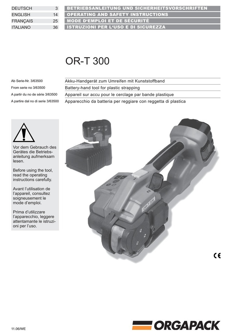
ORGAPACK OR-T 50
14 12.06/WE
1TECHNICAL DATA
TABLE OF CONTENTS
Weight 4 kg (8.8 lbs.)
Dimensions Length 400 mm (15.75“)
Width 130 mm (5“)
Height 200 mm (7.90“)
Strap tension With friction clutch fully
variable up to 2300 N
(510 lbs.) depending on strap
quality
Sealing Friction welded
Voltage Battery charger 230 V (115 V)
Battery 12 V
Emission sound pressure
levels, measurement
type A (EN ISO 11202) LpA 83 dB (A)
Vibrations at handle
(EN ISO 8662-1) ah,w 7,3 ms-2
PLASTIC STRAP
Strap quality Polypropylene (PP)
Polyester (PET)
Strap width 9–10, 12–13, 15–16 or 19 mm
(
3/8“, 1/2“, 5/8“ or 3/4“)
Strap thickness 0.5–1.0 mm (.019“–.039“)
Page
1 Technical data 14
2 General information 15
2.1 Information on environmental protection 15
3 Safety instructions 16
3.1 Safety instructions for battery
charger and battery 16
4 Description 17
4.1 Design 17
4.2 Battery charger indicators 17
5 Initial operation 18
5.1 Battery charger 18
5.2 First battery charge 18
5.3 Charging the battery 18
6 Operating instructions 19
6.1 Operating the tool 19
7 Preventive and corrective maintenance 22
7.1 Changing the battery 22
7.2 Adjusting welding time 22
7.3 Adjusting strap tension 23
7.4 Adjusting strap width 23
7.5 Cleaning the tool 24
7.6 Changing the tension wheel 24
7.7 Changing the tension shoe 24
8 Recommended spare parts 47
8.1 Parts list 47
Explosion drawing 53
DECLARATION OF AGREEMENT
According to norm:
EN ISO 12100-1, EN ISO 12100-2, EN 349,
EN 1050, EN 61000-6-1, EN 61000-6-3
CH-8953 Dietikon, 02.11.2005
Sales Manager General Manager Products
Packaging Technology: Packaging Technology:
R. Kieffer M. Binder
We take sole responsibility for declaring that the
tool OR-T 50, to which this declaration refers, is
in full compliance with the current requirements of
the guidelines laid down by the council on 22th
June 1998 (98/37/ECC), “Machine Guidelines“.
Furthermore, electrical installations are in compli-
ance with the guideline laid down by the council on
19. February 1973 (73/23/EEC) “Low Voltage Gui
delines“ and from 3th May 1989 (89/336/EEC)
“EMV Guidelines“.

ORGAPACK OR-T 50
15
12.06/WE
CAUTION!
Used where there is dan-
ger to life and health.
WARNING!
Used for danger which
can cause material
damage.
NOTE!
Used for general infor-
mation and information
which, if not followed
can cause faults in the
operating sequence.
2GENERAL INFORMATION
These operating instructions are intended to simplify
familiarisation with the strapping tool and its proper
use for the intended purpose. The operating instruc-
tions contain important information concerning the
safe, proper and efficient use of the strapping tool.
Compliance with the instructions will help to avoid
danger, reduce repairs and stoppages and increase
the reliability and service life of the strapping tool.
The operating instructions must always be available at
the place of operation of the strapping tool. They must
be read and observed by all persons concerned with
work on the strapping tool. This work specifically
includes operation, refilling of operating material, fault
elimination and maintenance.
In addition to the operating instructions and the regu-
lations for accident prevention effective in the country
of use and place of application, the recognised techni-
cal regulations for safety and proper operation must
also be observed.
2.1 INFORMATION ON ENVIRONMENTAL
PROTECTION
This tool is manufactured without any physical or che-
mical substances which could be dangerous to health.
For disposal of all the parts, the governmental instruc-
tions must be observed. The electrical assemblies
should be dismantled so that the mechanical, electro-
mechanical and electronic components can be dis-
posed of separately.
Dealers provide an
environmentally-
friendly battery
disposal service
• Do not open the
battery.
• Do not throw the
used battery into hou-
sehold waste, fire or
water.
Defective or used
batteries undergo a
complete recycling
process.

ORGAPACK OR-T 50
16 12.06/WE
ORGAPACK
Original
jklsfjklsdjš
lksdfjkl
jkljsdllkjjkljsd
fkljjklkjkljsdafj
asdfjklkjjkljklj
ksldafkjkljklš
jkljklkljsdafjlkj
jkljjkljklkljljlk
Original ORGAPACK spare
parts must be used exclusi-
vely!
Not using original spare parts
will dissolve the warranty and
the liability.
Use for the intended purpose
This tool is designed for strapping packages, pallet
loads and the like.
The tool was designed and manufactured to provide
safe handling during the strapping operation.
The tool is designed for use with plastic straps (poly-
propylene and polyester).
Possible misuse
The use of steel straps is not possible.
3.1 SAFETY INSTRUCTIONS FOR BATTERY
CHARGER AND BATTERY
Always inspect the electrical
plug and cable before use. If
damaged, they must be
replaced by qualified personnel.
• Do not charge other types of batteries (see chapter
5.1) and use original accessories only.
• Keep the battery charger slot free of foreign objects
and protect against dirt.
• Protect the battery charger against humidity and
use it in dry areas only.
• Do not open the battery. Protect the battery against
impact, heat and fire. Risk of explosion!
• When the battery is outside the battery charger,
cover its battery terminals to avoid short circuits
with metal objects. Risk of fire and explosion!
• Keep battery dry and protected against frost. Do
not store it at temperatures over 50°C or below
10°C.
• Damaged batteries should not be used longer.
3SAFETY INSTRUCTIONS
Inform yourself!
Read the operating instructions
carefully.
Preventive and corrective main-
tenance on the tool may only
be carried out by trained per-
sonnel.
Protect yourself!
When operating the tool, wear
eye, face and hand protection
(cut-proof gloves).
Power source!
Before starting preventive or
corrective maintenance, remo-
ve battery from the tool.
Warning:
Strap will snap forward!
When cutting the strap, hold
the upper portion and stand
safely away from the strap.
Caution:
The lower strap will snap
forward.
Warning:
Strap could break!
Do not stand in line with the
strap while it is tensioned. The
strap could break!
Caution:
Only strap packed goods!
Do not put hands or other parts
of the body between the strap
and the package during the
strapping process.
Caution:
Danger of squeezing!
Do not put your fingers into the
tension wheel area.
Do not use water!
Do not use water or steam to
clean the tool.
ORGAPACK OR-T 50
17
12.06/WE
4.2 BATTERY CHARGER INDICATORS
Ready for charging
Battery not inserted:
Main voltage is on.
Rapid charging
Rapid charging operates
until the battery is fully re-
charged. The battery char-
ger automatically switches to
toppic- and trickle charging.
Trickle charging
Battery inserted: The battery
charger is only delivering a
trickle charge because the
battery is already fully
charged.
Temperature
Warning: The battery is too
hot (or too cold). Trickle
charging only. The battery
charger automatically
switches to rapid charging
when the temperature is in
the permitted range again.
Error message
Warning: Battery can not be
charged (battery defective or
battery charger slot dirty).
4DESCRIPTION
4.1 DESIGN
1 Welding lever
2 Tension lever
3 Battery
4 Cutting device
5 Tension shoe
6 Tension wheel
7 Potentiometer „Welding time“
8 Indicator „Battery“
9 Battery charger
10 Adapter
For detailed information, refer to operating
instructions for the battery charger.
Flashing light
Continuous light
Continuous light
Quick flashing
Double flashing
Fig. 2
Fig. 1
2
1
65
4
9
87
3
10

ORGAPACK OR-T 50
18 12.06/WE
5.1 BATTERY CHARGER
230 V (115 V) battery chargers can be operated at
220 V or 240 V (110 V).
The battery charger is suitable only for charging
(NiCd/NiMH) batteries (voltage between 7.2 V and
14.4 V).
5INITIAL OPERATION
5.2 FIRST BATTERY CHARGE
Please not the following points in order to
obtain optimum battery life:
– Connect battery charger (4/3) to mains voltage.
– Insert adapter (4/2) into battery charger slot.
– Insert battery (4/1) into battery charger.
For the first charge, leave the battery in the char-
ger for at least five hours, regardless of the bat-
tery indicator. (The charging time for all subsequent
charges is about 60 minutes)
For all subsequent charges, only recharge the bat-
tery when the red indicator light on the tool comes
on (see section 7.1). Avoid constant charging
when the battery is not yet discharged. This will
ensure optimum battery capacity and life.
Maximum battery output will be reached after four or
five charging/discharging cycles.
5.3 CHARGING THE BATTERY
The charging process and error functions are indica-
ted by a green light (4/3), see chapter 4.2.
The charging time is approx. 60 min.
The maximum charging current flows when the tem-
perature of the battery is between 15–45°C. Avoid
charging at battery temperatures below 0°C.
If the battery is not to be used for a longer
period (several days), it should be removed
from the tool and charged in the battery
charger.
The intelligent charger with fuzzy control charges the
battery with the optimum rapid charging current, de-
pending on temperature and capacity. If fully charged,
a preserving charge will prevent self-discharge and
thus guarantee a long battery life.
Fig. 3
AL 60 DV 1419
7.2 V - 14.4 V
Fig. 4
32
1

ORGAPACK OR-T 50
19
12.06/WE
6.1 OPERATING THE TOOL
– Insert charged battery and close the bow spring
(5/1).
– Place the strap around the package and hold it with
the left hand so that the lower strap lead is approx.
20 cm (8“) away from the hand.
– Take the tool with the right hand and press the lever
towards the handle.
– Slide the strap lead under the tension shoe (6/2)
and under the cutting device (6/1) into the tool until
the stop is reached.
The lower strap is now approx. 5 cm (2“)
beyond the tool.
– Release the lever.
6OPERATING INSTRUCTIONS
12
Fig. 6
Fig. 5
1

ORGAPACK OR-T 50
20 12.06/WE
– Insert the strap from coil holder between the tension
wheel (7/3) and the tension shoe (7/2). Then insert
the strap into the slot of the cutting device (7/1) until
stop is reached.
– Hold the tool by the grip with the left hand and
move the tension lever with the right hand back-
and forward until the desired strap tension is rea-
ched.
The maximal strap tension is adjustable
(see chapter 7.3).
If the tool is used in a dusty environement, it is rec-
ommended to clean the tool regularly. The tension
wheel in particular should be kept clean (see chap-
ter 7.5).
Fig. 8
Fig. 7
12
3

ORGAPACK OR-T 50
21
12.06/WE
– Push lever to stop (sealing position). The left hand
remains on the handle of the tool to bear the coun-
terforce.
The straps are welded together and the
upper strap is cut off.
– Hold lever in this position (approx. 2 sec.) until
signal lamp (12/1) is switched off.
If the LED flashes green
the cooling time is running.
When the red light is on
continuously, the battery
must be charged (see
chapter 5.2).
When the red signal lamp lights up, no
welding is performed, since the remaining
charge in the battery is insufficient to ensure proper
welding of the straps.
– Press lever against the handle. Then swing the tool
away from the strapping to the right at the rear.
– Check the seal (refer to chapter 7.2).
– Bring back the tension lever to the intermediate
position, push the yellow welding lever towards the
tension lever. Now the tool is ready for sealing the
straps.
Green flashing
Continuous red light
Fig. 10
LED-Status Function
Led light off Battery fully charged
orange approx. 40% residual capacity
red battery empty
green cooling time
Fig. 11
Fig. 9

ORGAPACK OR-T 50
22 12.06/WE
7.1 CHANGING THE BATTERY
If the red signal lamp (12/1)
is lit continuously, the battery
must be charged (see
chapter 5.2).
– Open bow spring and remove discharged battery.
– Insert charged battery and lock with bow spring.
When changing the battery, the new battery
must only be inserted after approx. five
seconds to ensure that the electronic system can
reset to the initial position. If the battery change is too
rapid, the red signal lamp lights up and the unit remains
blocked.
7.2 ADJUSTING WELDING TIME
– The welding time can be infinitely adjusted with a
screwdriver (no 1), depending on strap quality and
dimension.
–
By turning the screw carefully clockwise, the welding
time will be longer, by turning counterclockwise it
will be shorter.
The printed circuit board could be damaged if
the screw is turned too far either clockwise or
anticlockwise.
Check appearance of seal (see fig. 14)
regularly.
1 Good seal (the complete surface is cleanly welded
without excess material being forced out sideways).
2 Poorly welded seal (not welded over the complete
surface), welding time too short.
3 Poorly welded seal (excess material is forced out
sideways), welding time too long.
An incorrectly welded strapping cannot
secure the package and can thus lead to
injuries.
Never transport or move packaged
goods with incorrectly welded seals.
7PREVENTIVE AND CORRECTIVE MAINTENANCE
Continuous red light
Fig. 14
Polypropylen (PP) / Polyester (PET)
1
23
Fig. 13
1
Fig. 12

ORGAPACK OR-T 50
23
12.06/WE
7.4 ADJUSTING STRAP WIDTH
– To change the strap width, the strap stop (16/2)
must be removed with the screw (16/1) from the tool
and refitted with washers (1.5 mm thick) according to
the width of the strap.
– Strap width 19 mm ( 3/4“) one washer
– Strap width 15–16 mm ( 5/8“) one washer
– Strap width 12–13 mm ( 1/2“) two washers
– Strap width 9–10 mm ( 3/8“) three washers
– Loosen screw (17/4) and remove knife bushing
(17/1).
– Remove pin screw (17/2) and move the pawl (17/3)
to desired position according to strap width. Tighten
pin screw (17/2)
– Insert washers between base plate and knife
bushing according to strap width.
– Tighten screw (17/4).
– Strap width 19 mm ( 3/4“) one washer
– Strap width 15–16 mm ( 5/8“) one washer
– Strap width 12–13 mm ( 1/2“) two washers
– Strap width 9–10 mm ( 3/8“) three washers
7.3 ADJUSTING STRAP TENSION
The maximum strap tension is determined
by the adjustment of the friction clutch. For
this reason two fork wrenches are supplied.
– Block the tension shaft with the small fork wrench
(SW 11).
– With the other fork wrench (SW 17) adjust the nut.
– Turning the nut in clockwise direction the strap
tension is increased.
– Turning the nut in counterclockwise direction the
strap tension is reduced.
Best results are achived by adjusting the
clutch to the maximum tension for the pa-
ckage being strapped. But not as tight that the tensi-
on wheel will turn over or the strap breaks.
Fig. 15
17
+
–
Fig. 17
10 mm
13 mm
16/19 mm
1
2
3
4
10/13 mm16/19 mm
Fig. 16
10 mm
13 mm
16/19 mm
21

ORGAPACK OR-T 50
24 12.06/WE
7.5 CLEANING THE TOOL
If the tool is used in a dusty environment, it is
recommended to clean the tool regularly.
The tension wheel (18/1) in particular should be kept
clean.
– Clean the tension wheel with the steel brush sup-
plied with the tool.
7.6 CHANGING THE TENSION WHEEL
Removal
– Open bow spring (19/2) and remove battery (19/1).
– Block the tension shaft (19/9) with the small fork
wrench (SW 11).
– With the other fork wrench (SW 17) loosen the nut.
– Remove five spring washers (19/4) and carrier
(19/3).
– Press tension lever and remove pin (19/10).
– Remove tension wheel (19/7) together with the
clutch disks (19/6) and (19/8).
– Check clutch disks for wear, if necessary replace
it. Replace tension wheel.
Installation
– Install the parts in reverse order.
Do not lubricate the clutch disks. Adjust
the maximum tension force (see chapter 7.3).
7.7 CHANGING THE TENSION SHOE
Removal
– Open bow spring (20/2) and remove battery (20/1).
– Push the tension lever forward until the stop is
reached.
– Remove set screw (20/5) with compression spring
(20/6) and bolt (20/7).
– Release set screw (20/9).
– Push out shaft (20/8) with a small screwdriver.
– Raise rocker unit (20/10) and remove and replace
tension shoe (20/3).
– Clean tooth plates and tension wheel.
Installation
– Install the parts in reverse order.
Before inserting the rocker unit (20/10) lift
stroke lever (20/4) that the switch link of the
rocker lies below the stroke lever.
Afer mounting the shaft turn the tension wheel until
the rocker moves down. Screw in set screw (20/9)
until it is in line with the casing.
Fig. 20
12 V
NT C
max.50
0
C
1
2
3
4
567
10
8
9
Fig. 19
12 V
NT C
max.50
0
C
1
23
4
5
6
7
8
9
10
Fig. 18
1

47 12.06/WE
ORGAPACK OR-T 50
Pos. Artikel-Nr. Benennung Part name Article Articolo Stück
Part no Quantity
No d‘article Pièce
Art. nr. Pezzi
39 1821.048.002 Zahnplatte Tooth plate Plaque dentée Piastra dentata 2
41 1821.048.004 Spannschuh Tension plate Plaque de tension Scarpina per tensione 1
87 1821.047.003 Spannrad Tension wheel Molette de tension Rotella di tensione 1
89 1830.000.262 Kupplungsscheibe Clutch disc Disque d’embrayage Disco frizione 2
126 1821.020.042 Scheibe Washer Rondelle Rondella 6
129 1911.804.127 Senkschraube, M 4 x 12 Counter sunk screw Vis noyée Vite a testa svasata 2
8
Empfohlene Ersatzteile Recommended spare parts Pièces de rechange recommandées Parti di ricambio consigliate
Bei Bestellungen immer Artikel-Nr. angeben When ordering please indicate part number Lors d‘une commande, veuillez indiquer Nelle ordinazione indicare sempre il numero
e numéro d‘article dell‘articolo
8.1 Teileliste 1832.002.020/1.4 8.1 Parts list 8.1 Liste des pièces 8.1 Lista delle parti
Bei Bestellungen immer Artikel-Nr. angeben When ordering please indicate part number Lors d‘une commande, veuillez indiquer Nelle ordinazione indicare sempre il numero
le numéro d‘article dell‘articolo
1 1832.011.146 Grundplatte, inkl. Pos. 2-4 Base plate, incl. pos. 2-4 Plaque de base, incl. pos. 2-4 Piastra di base, incl. pos. 2-4 1
2 1935.506.100 Radial-Gleitlager, ø 6/8 x 10 Slide bearing Palier lisse Bronzina radiale 2
3 1935.506.060 Radial-Gleitlager, ø 6/8 x 6 Slide bearing Palier lisse Bronzina radiale 1
4 1922.104.123 Passkerbstift, ø 4 x 12 Grooved dowel pin Goupille cannelée Spina scanalata 2
5 1933.906.090 Nadelbüchse, ø 6/10 x 9 Needle bushing Palier à aiguille Bussola ad aghi 1
6
7 1910.604.082 Gewindestift, M 4 x 8 Set screw Goujon fileté Perno filettato 1
8 1832.011.153 Gehäuseschalen Set, inkl. Pos. 9 Set of housing parts, incl. pos. 9 Pièces du bâti, incl. pos. 9 Involucri, incl. pos. 9 1
9 1960.000.599 Deckel, ø 10 Cover Couvercle, Coperchio 1
10
11 1832.011.027 Abdeckung Cover Couvercle, Copertura 1
12 1821.019.001 Bügelfeder Bow spring Ressort Molla 1
13
14
15 1914.635.160 PT-Schraube, KA 35 x 16 PT-Screw Vis PT Vite PT 6
16 1914.635.300 PT-Schraube, KA 35 x 30 PT-Screw Vis PT Vite PT 2
17 1914.404.128 Linsenschraube, M 4 x 12 Head screw Vis à tête Vite a testa svasata 4
18 1821.033.009 Bolzen Bolt Goujon Albero 1
19
20 1832.031.001 Wippe rechts, inkl. Pos. 21 Rocker right, incl. pos. 21 Bascule de droite, incl. pos. 21 Bilanciere a destra, incl. pos. 21 1

48 12.06/WE
ORGAPACK OR-T 50
Pos. Artikel-Nr. Benennung Part name Article Articolo Stück
Part no Quantity
No d‘article Pièce
Art. nr. Pezzi
21 1935.508.120 Radial-Gleitlager, ø 8/10 x 12 Slide bearing Palier lisse Bronzina radiale 3
22 1926.502.160 Hülsenfreilauf, ø 16/22 x 26 Bearing Roulement Ruota libera 1
23 1911.803.128 Senkschraube, M3 x 12 Counter sunk screw Vis noyée Vite 1
24 1911.006.208 Zylinderschraube, M 6 x 20 Cylinder screw Vis cylindrique Vite cilindrica 1
25 1919.606.072 Sicherungsscheibe, M 6 Lock washer Rondelle de sécurité Ranella di sicurezza 1
26 1921.405.451 Spiralstift, ø 5 x 45 Spiral pin Goupille élastique Coppiglia elastica 1
27
28
29 1832.031.041 Wippe links, inkl. Pos.4,21,26,32,36 Rocker left Bascule gauche Bilanciere a sinistra 1
30
31
32 1921.406.201 Spiralstift, ø 6 x 20 Spiral pin Goujon Coppiglia elastica 2
33 1832.031.011 Finger Bolt Goujon Perno 1
34 1821.010.018 Druckfeder Compression spring Ressort de compression Molla a pressione 1
35 1820.030.092 Gewindestift Set screw Goujon fileté Perno filettato 1
36 1933.716.160 Nadelhülse, ø 16/22 x 16 Needle bushing Palier à aiguille Bussola ad aghi 1
37 1821.039.006 Bolzen Bolt Goujon Spinello 1
38
39 1821.048.002 Zahnplatte Tooth plate Plaque dentée Piastra dentata 2
40 1821.205.014 Distanzplatte Spacer plate Plaque d’écartement Distanziatore 1
41 1821.048.004 Spannschuh Tension plate Plaque de tension Scarpina per tensione 1
42
43 1832.041.004 Anschlag Stop Butée Battuta 1
44 1921.404.261 Spiralstift, ø 4 x 26 Spiral pin Goupille élastique Spina elastica 2
45
46
47 1832.022.002 Schweissschuh Welding shoe Plaque de soudure Piastra di saldatura 1
48 1821.033.007 Bolzen Bolt Goujon Spinotto 1
49 1923.501.120 Splint, ø 2 x 12 Cotter pin Goupille fendue Coppiglia 1
50 1832.022.123 Zahnplatte Tooth plate1 Plaque dentée Piastra dentata
51
52
53
54 1933.706.090 Nadelhülse, ø 6/10 x 9 Needle bushing Palier à aiguille Bussola ad aghi 1
55 1832.033.006 Exzenterwelle Eccentric shaft Arbre excentrique Albero eccentrico 1
56 1917.401.065 Distanzscheibe, ø 6/18 x 0,5 Spacer disk Disque d’écartement Rondella distanziatrice 4
57 1832.011.022 Flansch Flange Bride Flangia 1
58 1911.004.128 Zylinderschraube, M 4 x 12 Cylinder screw Vis cylindrique Vite cilindrica 3

49 12.06/WE
ORGAPACK OR-T 50
Pos. Artikel-Nr. Benennung Part name Article Articolo Stück
Part no Quantity
No d‘article Pièce
Art. nr. Pezzi
59 1911.004.088 Zylinderschraube, M 4 x 8 Cylinder screw Vis cylindrique Vite cilindrica 2
60 1821.250.003 Präzisions-Wellenkupplung, inkl. Pos. 61 Coupling, incl. pos. 61 Accouplement, incl. pos. 61 Giunto, incl. pos. 61 1
61 1910.703.062 Gewindestift, M 3 x 6 Set screw Goujon fileté Perno filettato 4
62
63 1933.710.150 Nadelhülse, ø 10/14 x 15 Needle bushing Douille d’aiguille Bussola ad aghi 1
64 1821.140.002 Motor Motor Moteur Motore 1
65 1832.022.001 Pleuel Connecting rod Bielle Biella 1
66 1821.205.013 Lasche Link Eclisse Giunto 1
67 1821.031.015 Bolzen Bolt Goujon Spinotto 2
68 1920.103.062 Sicherungsscheibe, ø 3,2 Lock washer Rondelle de sécurité Anello di sicurezza 4
69
70 1832.022.006 Druckhebel Pressure piece Levier Leva a pressione 1
71
72
73 1832.022.004 Hubplatte Stroke piece Elévateur Piastra elevatrice 1
74 1821.020.039 Druckrolle Press roll Galet de pression Rullo di pressione 1
75 1821.030.014 Bolzen Bolt Goujon Spinotto 1
76 1821.039.008 Gewindestift Set screw Goupille filetée Perno esagonale 1
77 1821.011.003 Zugfeder Tension spring Ressort à tension Molla di torsione 1
78 1821.019.003 Tellerfeder, ø 18/8,2 x 1 Saucer spring Rondelle bombée Ranella a tazza 9
79 1821.031.016 Bolzen Bolt Goujon Spinotto 1
80 1920.105.072 Sicherungsscheibe, ø 5 Lock washer Rondelle de sécurité Anello di sicurezza 9
81
82
83 1832.033.005 Spannwelle Tension shaft Arbre de tension Albero di tensione 1
84 1830.000.062 Scheibenfeder Key Coin Ranella 1
85 1821.030.024 Stift Pin Goupille Spina 2
86 1821.255.002 Mitnehmerscheibe Carring disc Disque entraîneur Disco di trascinamento 1
87 1821.047.003 Spannrad Tension wheel Molette de tension Rotella di tensione 1
88 1821.255.001 Mitnehmer Carrier Entraîneur Trascinatore 1
89 1830.000.262 Kupplungsscheibe Clutch disc Disque d’embrayage Disco frizione 2
90 1925.210.122 Tellerfeder, ø 25/12,2 x 1,5 Saucer spring Rondelle bombée Ranella a tazza 5
91 1820.020.163 Mutter Nut Ecrou Dado 1
92 1832.039.007 Ring Ring Anneau Anello 1
93
94 1820.010.182 Zugfeder Tension spring Ressort de traction Molla di tensione 1
95

50 12.06/WE
ORGAPACK OR-T 50
Pos. Artikel-Nr. Benennung Part name Article Articolo Stück
Part no Quantity
No d‘article Pièce
Art. nr. Pezzi
96
97 1930.180.356 Rillenkugellager Bearing Roulement à billes Cuscinetto 1
98 1821.020.037 Büchse Bushing Douille Bussola 1
99
100 1821.080.003 Spannhebel komplett, inkl. Pos. 102 Tension lever complete, incl. pos. 102 Levier de tension complet,incl. pos. 102 Leva di tensione completa, incl. pos. 102 1
101
102 1820.080.051 Kugelgriff Knob Poignée sphérique Pomolo 1
103
104 1832.039.008 Klinke Pawl Cliquet Leva 1
105 1832.039.009 Klinke Pawl Cliquet Leva 1
106 1820.010.149 Drehfeder Torsion spring Ressort de combinè Molla di torsione 1
107 1821.031.013 Bolzen Bolt Goujon Spinotto 2
108
109
110
111 1821.084.002 Schweisstaste Welding lever Levier de soudure Leva di saldatura 1
112 1821.012.007 Drehfeder Torsion spring Ressort de torsion Molla di torsione 1
113 1821.031.014 Bolzen Bolt Goujon Spinotto 1
114 1820.040.060 Sperrad Locking wheel Roue à rochet Rondella d’arresto 1
115 1821.089.005 Schaltlasche komplett Switch link complete Eclisse d’entraînement complète Linguetta completa 1
116
117
118
119
120
121 1917.401.165 Distanzscheibe, ø 16/28 x 0,5 Spacer disk Disque d’éncartement Rondella distanziatrice 3
122 1920.112.132 Sicherungsscheibe, ø 12 Lock washer Rondelle de sécurité Anello di sicurezza 1
123
124
125 1832.041.002 Bandführung Strap guide Guidage pour bande Guida reggetta 1
126 1821.020.042 Scheibe Washer Rondelle Rondella 4
127
128
129 1911.804.127 Senkschraube, M 4 x 12 Counter sunk screw Vis noyée Vite a testa svasata 2
130
131 1821.209.003 Messerhülse Knife sleeve Douille de couteau Bussola coltello 1
132 1832.042.035 Klinke Pawl Cliquet Leva 1
133 1820.030.418 Spez. Schraube Special screw Vis spéciale Vite speziale 1

51 12.06/WE
ORGAPACK OR-T 50
Pos. Artikel-Nr. Benennung Part name Article Articolo Stück
Part no Quantity
No d‘article Pièce
Art. nr. Pezzi
134 1821.010.019 Druckfeder Compression spring Ressort de compression Molla di pressione 1
135
136 1821.209.016 Abschneidmesser komplett Knife complete Couteau complète Coltello completa 1
137
138 1821.012.008 Drehfeder Torsion spring Ressort de torsion Molla di torsione 1
139
140
141 1832.022.007 Hubhebel Stroke lever Levier élévateur Leva di sollevamento 1
142 1821.020.040 Büchse Bushing Douille Bussola 1
143 1821.030.013 Bolzen Bolt Goujon Spinotto 1
144 1821.039.005 Bolzen Bolt Goujon Spinotto 1
145
146
147
148
149
150 1821.152.007 Steuerprint Printed circuit board Carte circuit imprimé Circuito stampato 1
151
152
153 1914.630.100 PT-Schraube, KA 30 x 10 PT-Screw Vis PT Vite PT 4
154
155 2179.110 Akku, 12 V, inkl. Pos. 156 Battery, 12 V, incl. pos. 156 Accumulateur, 12 V, incl. pos. 156 Accumulatore, 12 V, incl. pos. 156 1
156 1821.090.012 Firmenschild “Akku“ Name tag “Battery“ Plaque „Accumulateur“ Targhetta „accumulatore“ 1
157 2179.220 Set Ladegerät/Adapter, 230 V, EU Charger/adapter set, 230 V EU Jeu de chargeur/adapteur, 230 V, EU Serie caricatore/adattore, 230 V 1
158
159 2179.221 Set Ladegerät/Adapter,115 V, USA Charger/adapter set, 115 V USA Jeu de chargeur/adapteur, 115 V, USA Serie caricatore/adattore, 115 V, USA 1
160 2179.222 Set Ladegerät/Adapter,100 V, Japan Charger/adapter set, 100 V Japan Jeu de chargeur/adapteur, 100 V, JP Serie caricatore/adattore, 100 V, Japan 1
161 2179.115 Adapter Adapter Adaptateur Adattore 1
162
163 1821.090.021 Firmenschild “Ladegerät“ Name tag “Battery charger“ Plaque „Chargeur pour accumulateur“ Targhetta „caricatore“ 2
164 1821.091.039 Typenschild Type plate Plaque de type Placcetta de tipo 1
165
166
167 1832.011.078 Einlage kurz Insert short Entretoise court Supporto anteriore corto 1
168 1832.011.079 Einlage lang Insert long Entretoise long Supporto anteriore lungo 1
169
170 1821.092.016 Hinweisschild “CE“ Indication plate “CE“ Plaquette indicatrice “CE“ Targhetta “CE“ 1
171 1821.092.017 Hinweisschild “1“ Indication plate “1“ Plaquette indicatrice “1“ Targhetta “1“ 1

52 12.06/WE
ORGAPACK OR-T 50
Pos. Artikel-Nr. Benennung Part name Article Articolo Stück
Part no Quantity
No d‘article Pièce
Art. nr. Pezzi
172 1821.092.020 Hinweisschild “2“ Indication plate “2“ Plaquette indicatrice “2“ Targhetta “2“ 1
173 1821.092.013 Hinweisschild “Sicherheit“ Indication plate “Safety“ Plaquette indicatrice “Sécurité“ Targhetta “Sicurezza“ 1
174
175
176
177
Werkzeuge Tools Outils Utensile
178 1990.199.001 Stahldrahtpinsel Steel brush Brosse métallique Penello con filo d‘accio 1
179 1990.101.017 Gabelschlüssel, SW 17 Wrench, SW 17 Clef à fourche, SW 17 Chiave a forchetta, SW 17 1
180 1990.101.011 Gabelschlüssel, SW 11 Wrench, SW 11 Clef à fourche, SW 11 Chiave a forchetta, SW 11 1
181
Optionen Option (on request) Option (sur demande) Opzioni
182 2179.813 Aufhängebügel komplett, inkl. Pos. 183 Suspension bow compl., incl. pos. 183 Crochet de suspension complète Maniglia di sonspensione comleta 1
183 1912.704.358 Linsenschraube, M 4 x 35 Oval head screw Vis à tête bombée Vite a testa svasata 1

53 12.06/WE
41
39
39
40
100
106
105
104
115
114
80
122
22
20
21
24
48
47
78
73
68
67
67
79
80
80
1
66
49
43
65
44
1832.002.020/1
68
136
37
144
OR-T 50
80
107
113
112
111
121
121 121
143
142
129
125
131
129
85
84
98
33
29
34
35 36
26
107
25
70
75
138
74
141
68
77
a)7
133
132
134
126
126
(c)137)
56
56
86
91
90
88
89
87
89
92
94
97
63
a)58 50
133
20.09.05 nm/hp
d)102
18
a)58
32
83
60
57
55
56
56
64
a)58
a)59
a)58
a)59
54
5
a)61
4
a)Loctite 222 c)Loctite 406 d)Loctite 480
a)76
17 16
17
183
11
8
155
15
15
153
15
16
15
a
156
182
173
167
98
17
17
150
12
173
168
21 21
2
3
2
157 (230 V)
159 (115 V)
160 (100 V)
161
171
172 170
23
163
164
163
Other manuals for OR-T 50
1
Table of contents
Other Orgapack Power Tools manuals

Orgapack
Orgapack OR-T 85 Quick guide

Orgapack
Orgapack H-1334 User manual

Orgapack
Orgapack OR-T 300 User manual

Orgapack
Orgapack OR-H 47 User manual

Orgapack
Orgapack OR-T 300 Quick guide

Orgapack
Orgapack OR-T 400 User manual

Orgapack
Orgapack OR-T 200 Quick guide

Orgapack
Orgapack OR-T 100 Manual

Orgapack
Orgapack OR-T 200 Quick guide
Popular Power Tools manuals by other brands

EGAmaster
EGAmaster AQUAMaster 79902 operating instructions

Central Pneumatic
Central Pneumatic 68029 Set up and operating instructions

BLACK DECKER
BLACK DECKER BCS601 manual

DOUGHXPRESS
DOUGHXPRESS TXM-15CP Lil Chick owner's manual

MEISTER CRAFT
MEISTER CRAFT MPS 710 E-P manual

Power Fist
Power Fist 8873127 manual