MetalMaster MG-440 User manual
MECHANICAL GUILLOTINE
OPERATION MANUAL
Edition No : MGG-1
Date of Issue : 10/2016
Models.
MG-440, MG-840
Page 1
Instructions Manual for MG-440 (S924A)
07/02/2018
2
OPERATION MANUAL
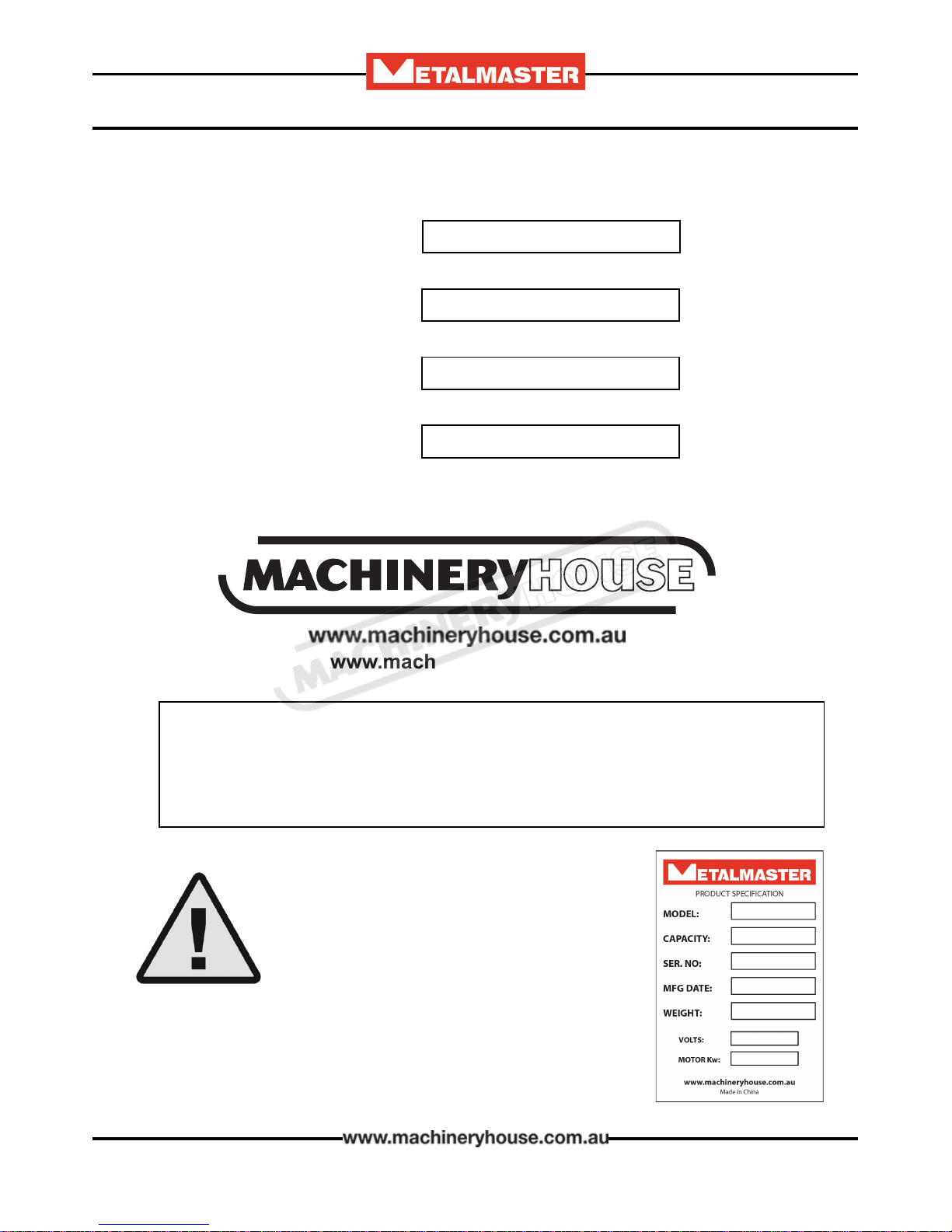
NOTE:
In order to see the type and model of the machine, please see the
specication plate. Usually found on the back of the machine. See
example (Fig.1)
Fig.1
MECHANICAL GUILLOTINE
MACHINE
MODEL NO.
SERIAL NO.
DATE OF MANF.
Note:
is manual is only for your reference. Owing to the continuous improvement of the
machine, changes may be made at any time without obligation or notice. Please ensure
the local voltage is the same as listed on the specication plate before operating this
electric machine.
Distributed by
www.machineryhouse.co.nz
MACHINE DETAILS
Page 2
Instructions Manual for MG-440 (S924A)
07/02/2018
3
OPERATION MANUAL
C O N T E N T S:
1. GENERAL MACHINE INFORMATION
1.1 Specications.................................................................4
1.2 Standard Equipment.....................................................4
1.3 Overall Drawings..........................................................5
2. IMPORTANT INFORMATION
2.1 Safety Requirements......................................................6
2.2 Features of the Machine...............................................8
2.3 Liing Instructions.......................................................9
3. INSTALLATION
3.1 Base Foundation and Securing Points......................10
3.2 Machine Leveling.........................................................11
3.3 Checking the Power Supply........................................11
3.4 Attaching e Accessories..........................................12
4. COMMISSIONING
4.1 Preparation of the Machine........................................13
4.2 Omrom E3z Safety Sensor Alignment......................13
4.3 Manual Back Gauge.....................................................16
4.4 Commissioning Check List........................................16
5. OPERATION INSTRUCTION
5.1 Pre-Operational Safety Check Prior to Operating..17
5.2 Start Up.........................................................................18
5.3 Adjusting Of e Blade Gap......................................19
6. MAINTAINANCE
6.1TypeAndFrequency Of Inspections...........................20
6.2 Lubrication Points.......................................................21
6.3 Brake Adjustment........................................................22
6.4 Calibrate Rapid Blade Adjustment Dial....................23
6.5 Top Position Cam Adjustment..................................24
APPENDIX
A. Electrical Diagram.......................................................25
Risk Assessment Sheets.....................................................26
Page 3
Instructions Manual for MG-440 (S924A)
07/02/2018
4
OPERATION MANUAL
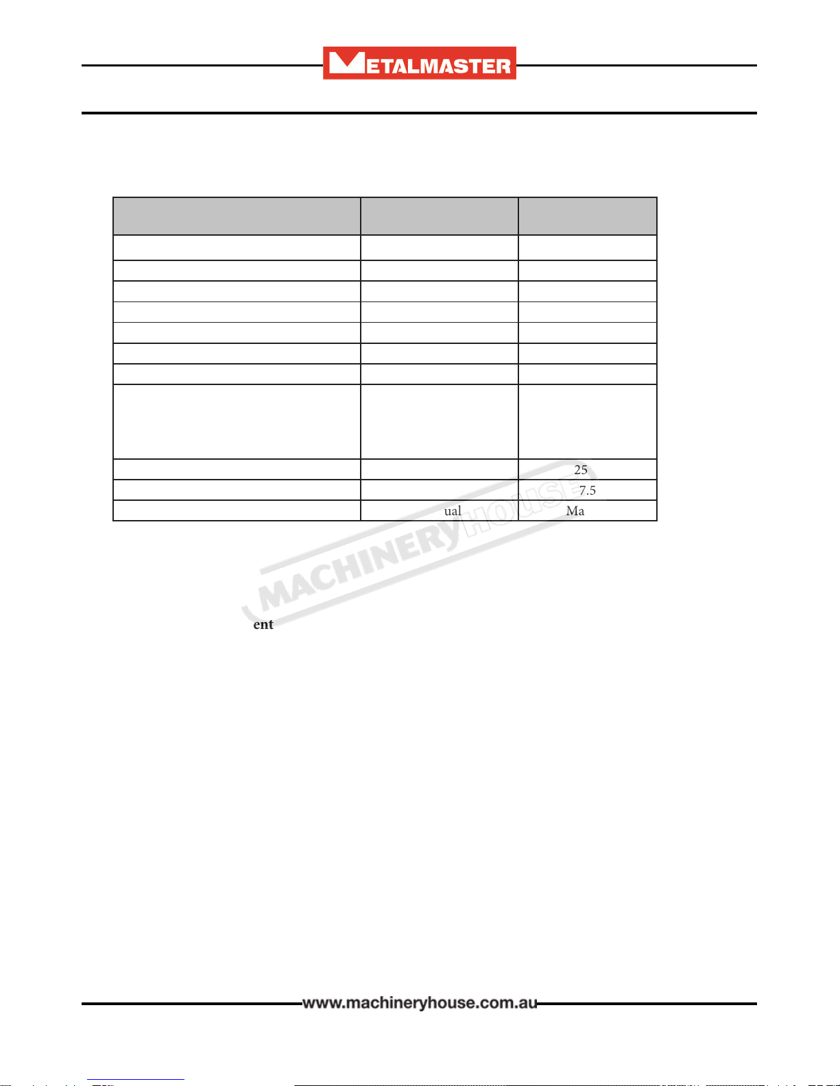
Machine Type MG-440 MG-840
Shearing Length (mm) 1300 2500
Material Capacity Mild Steel (mm) 4 4
Material Capacity Stainless Steel (mm) 2.5 2.5
Shear Angle (degree) 2 2
Back Gauge Range (mm) 750 750
Back Gauge Type Rack & Pinion Rack & Pinion
Strokes per Minute 22 28
Dimensions Width (mm)
Depth (mm)
Height (mm)
1860
2210
1180
3124
2398
1290
Weight (kgs) 1440 2500
Main Motor 3 Phase 415 Volt 50Hz (kW) 4 7.5
Back Gauge Manual Manual
1.1 SPECIFICATIONS:
1.2. Standard Equipment:
Instruction Manual
Back-gauge assembly
Front guarding
Footswitch and control panel
Page 4
Instructions Manual for MG-440 (S924A)
07/02/2018
5
OPERATION MANUAL
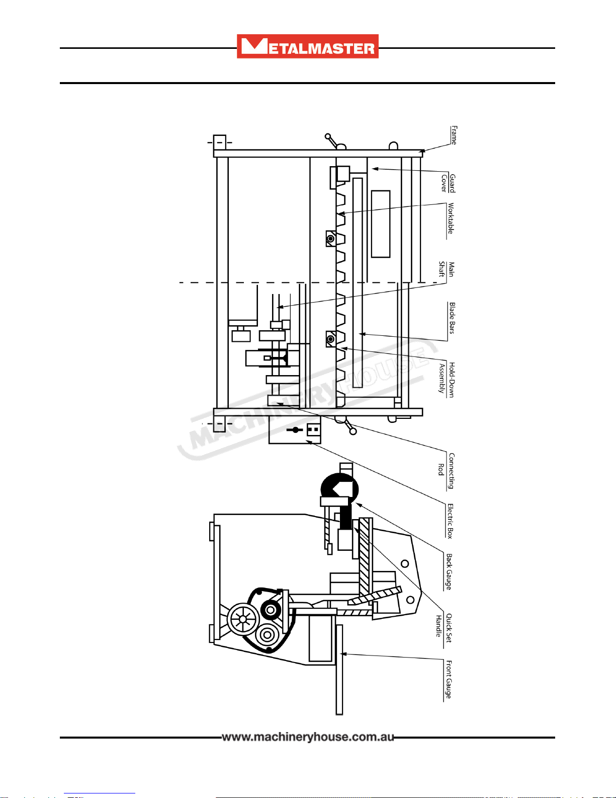
1.3 OVERALL DRAWING
Page 5
Instructions Manual for MG-440 (S924A)
07/02/2018

6
OPERATION MANUAL
e most common metal guillotine injuries are crushed or amputated ngers.
Most of these accidents are not caused by the blade of the guillotine, but by the clamps that hold
the sheet metal being cut. Other injuries are from ngers jamming under the sheet that is to be
cut, and strain injuries while handling large and awkward sheets of metal.
By law, guillotines must be guarded, and operators must be trained. Safe working procedures must
be developed to prevent injuries.
2.1 SAFETY REQUIREMENTS
DO NOT use this machine unless a Qualied person has instructed you in its safe use and opera-
tion of the machine.
e following topics can be used as a guide to identify workplace hazards and to reduce the risks of
operating metal guillotines.
It is an unsafe practice for two people to work at a guillotine unless both operators are provided
with interlocked actuating devices (usually a foot control). However in some guillotine operations,
for example cutting large sheets, two operators may be required to maneuver sheets into position
before cutting. For such operations safe work procedures should be developed to control any
hazards.
Safety glasses must be worn at
all times in work areas. Earmus
should be worn if the work area is
noisy.
Sturdy footwear must be worn at
all times in work areas.
Gloves should be worn when
handling the material used on this
machine.
Long and loose hair must be
contained with a net or under a
hat
Page 6
Instructions Manual for MG-440 (S924A)
07/02/2018

7
OPERATION MANUAL
SAFETY CHECKS BEFORE OPERATING
qEnsure xed guards are in place to prevent hands or other parts of the body from entering the
trapping space.
qGuards or safety devices must never be removed or adjusted, except by an authorized person
for maintenance purposes.
qWorking parts should be well lubricated and free of rust and dirt.
qe area around the machine must be adequately lit and kept free of materials, which might
cause slips or trips.
qBe aware of other personnel in the immediate vicinity and ensure the area is clear before using
equipment.
qFamiliarize yourself with and check all machine operations and controls.
qEnsure cutting table is clear of scrap and tools.
qFaulty equipment must not be used. Immediately report suspect machinery
SAFETY CHECKS WHEN OPERATING
qDo not attempt to cut material beyond the capacity of the machine.
qNever attempt to cut rod, strap or wire with this machine.
qUse correct liing procedures when handling large sheets of material.
qTake extreme care during the initial feeding of the workpiece into the machine.
qe workpiece should always be held suciently far back from the edge being fed into the
guillotine.
qEnsure ngers and limbs are clear before actuating the guillotine.
qHold material rmly to prevent inaccurate cutting due to creep.
qWhen cutting ensure feet are positioned to avoid contact with the foot operated lever.
SAFETY CHECKS AFTER OPERATION
qRemove all o cuts and place them in either the storage rack or waste bin.
qLeave the work area in a safe, clean and tidy state.
POTENTIAL HAZARDS
qCuts from the sharp edges and burrs on the sheets before and aer cutting
qParts of the body being caught in crush and pinch points.
qInjuries caused when handling metal sheets
Page 7
Instructions Manual for MG-440 (S924A)
07/02/2018
8
OPERATION MANUAL
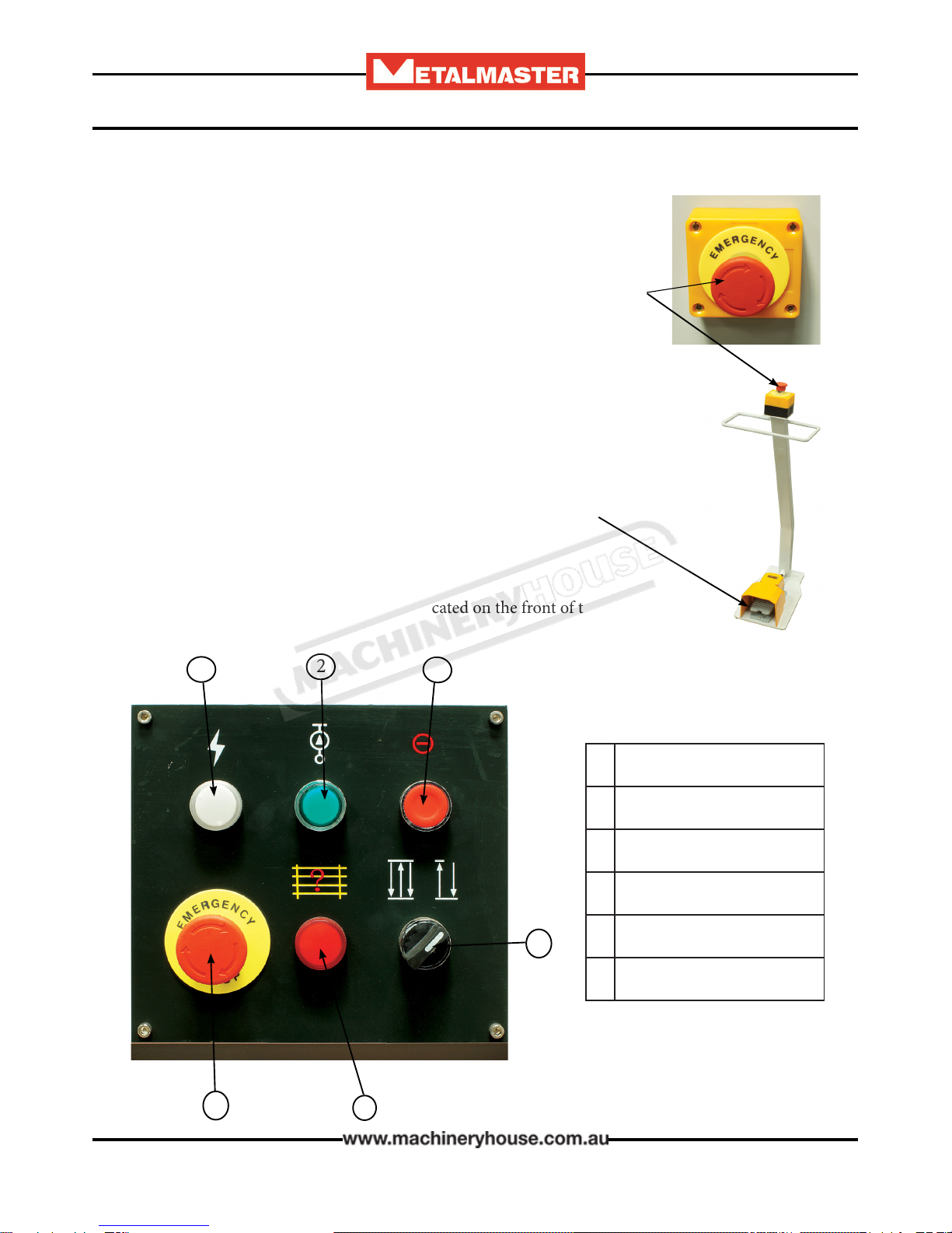
e electrical circuits of your machine are designed to allow operation
with maximum safety. e following precautions are available on the ma-
chine for enhanced safety.
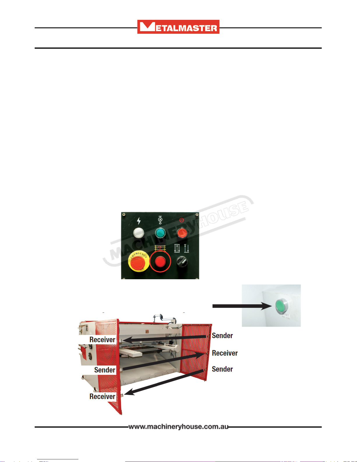
ere are three Emergency stop buttons (engaging type). ey are found
on the foot switch, control unit, and on the front of the machine. Once the
buttons has been pressed to reset the emergency stop, the red button must
be rotated.
2.2. FEATURES OF THE MACHINE:
Foot pedal control
e foot pedal when pressed activates the beam and must be held in the de-
pressed position until the machine has completed its cut.
Release the foot pedal during the cutting operation and the blade will stop and
stay in that position. To make it return to the top of the stroke the foot pedal
must be pressed again and held until the cycle has been completed.
Main Controls
e main machine operating controls are located on the front of the
machine.
12
3
4
56
1 Power ON Light
2 Illuminated Start Button
3 Electrics OFF
4 Continuous or Single cut
5 Emergency Stop
6Rear Safety Guard
Page 8
Instructions Manual for MG-440 (S924A)
07/02/2018
9
OPERATION MANUAL
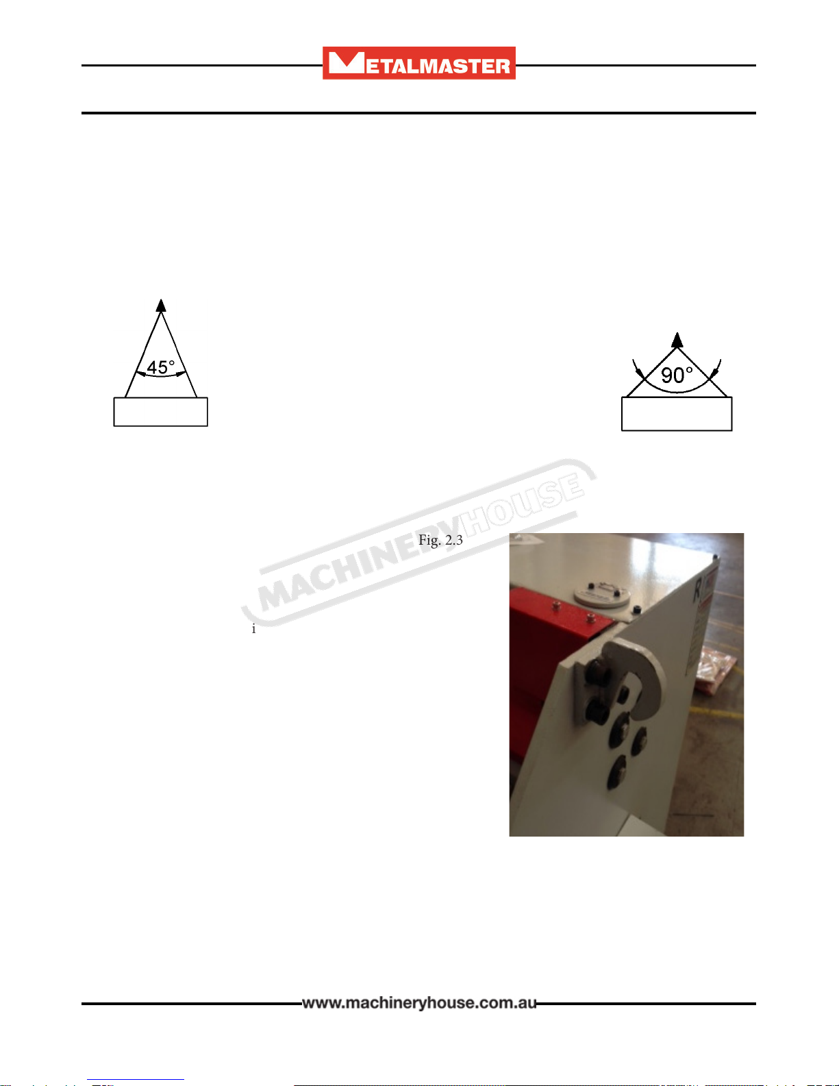
2.3 LIFTING INSTRUCTIONS
On the day that the machine arrives, make sure that a crane with sucient capacity is available to
unload the machine from the vehicle. Ensure access to the chosen site is clear and that doors and
ceilings are suciently high and wide enough to receive the machine.
To handle the Guillotine, use only the two sling liing points located on the top of the end plates.
(Fig. 2.3) e slings should be positioned so the machine is level when lied.
When using slings please take note of the sling angle and the loads that apply
When the slings are at a 45° angle then each sling is carrying
the equivalent of 50% of the load weight. (Fig.2.1).
When the slings are at a 90° angle then each sling will have
a weight equal to 75% of the load on each sling.
(Fig 2.2)
Note! Metalmaster recommend not to exceed 90° angle
Fig 2.2
Fig 2.1.
When liing the machine use only certied liing slings
Ensure that when liing, the machine does not tip over.
Check that the liing slings do not interfere with the hydraulic
pipes or electrical conduits.
Failure to follow these instructions could cause damage to the
machine
Liing Points
Fig. 2.3
Page 9
Instructions Manual for MG-440 (S924A)
07/02/2018
10
OPERATION MANUAL
e machine is delivered in a complete assembled execution. It must be leveled and rmly sta-
tioned on the oor where it is to be used, according to the Installation Diagram attached. Indoor
installation and a dry working environment without danger of re and explosion is necessary.
e oor load, where the machine is to be installed, must be suitable for the weight of the machine.
3. INSTALLATION
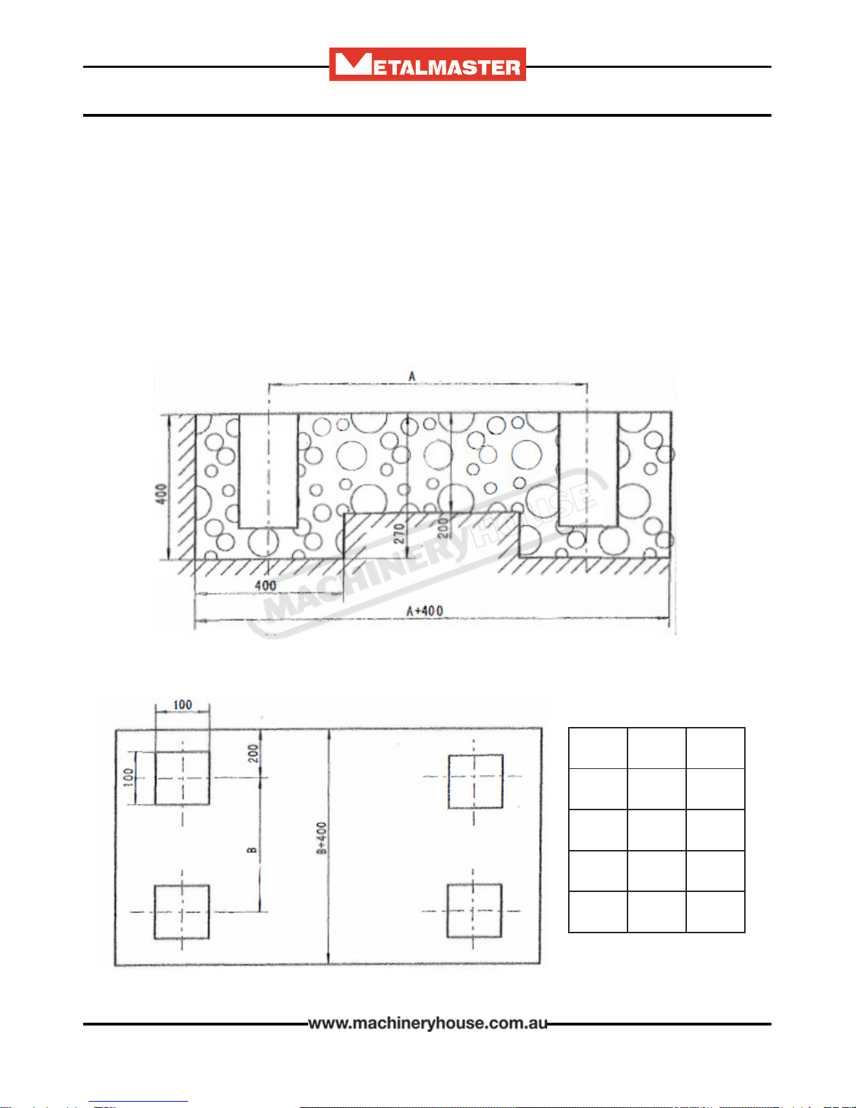
3.1 BASE FOUNDATION AND SECURING POINTS
Before securing the machine a solid concrete base must be prepared to the specication of the
machine.
e sizes for the bolt holes position are listed as A-B.
Size A B
1250
1300 1640 500
2000 2040 500
2500 2504 500
3000
3050 3379 625
Page 10
Instructions Manual for MG-440 (S924A)
07/02/2018

11
OPERATION MANUAL
3.3 Checking e Power Supply
METALMASTER machines are supplied wired ready to run. Check the specication plate on the
machine to conrm the correct voltage of the power supply.
Check the rotation of the motor is correct.
e machine must be connected to the power only by a qualied and licensed electrician.
Warranty may be voided if it is found that the connection was not carried out by a qualied
electrician.
3.2 MACHINE LEVELING
To set your machine up so that it operates to optimum performance, apply the following procedure
Aer your guillotine has been anchored to a concrete slab oor, it then needs to be leveled. e
leveling is performed using each of the screws on each pad.(Fig. 3.1). Loosen the hold down bolts
and place a level on the surface of the working table. Tolerances: 1000:0.30mm, for both longitudi-
nal and transverse.
Metal plates need to be placed under each jacking screw to distribute the load. Once level then
tighten the hold down bolts.
Metal Plate
Jacking Screw
e machine must not rest on supports other
than those dened in Fig. 3.1
Fig. 3.1
Page 11
Instructions Manual for MG-440 (S924A)
07/02/2018

12
OPERATION MANUAL
Fig. 3.2
q Place the squaring stops Fig 3.3 into position on the table top,
securing into place with the bolts supplied. Check that the square
stops are square to the blade. Adjust by loosening the bolts and
moving by the amount allowed by the clearance of the holes.
q Re tighten the screws.
Fig. 3.3
3.4 ATTACHING THE ACCESSORIES.
q Bolt the support arms onto the feed table. Ensure they are level and square to the table. (Fig 3.2)
q Unpack and attach the rear fence to the back of the machine. Ensure that the sensors have been
connected and set up. (Fig.3.4)
q Unpack the mobile foot control and plug the into the socket provided on the machine. (Fig.3.5)
Fig. 3.4
Fig. 3.5
Page 12
Instructions Manual for MG-440 (S924A)
07/02/2018
13
OPERATION MANUAL
4. COMMISSIONING
4.1. PREPARATION OF THE MACHINE.
q Remove all wrapping and packing grease from the machine.
q Check the machine for loose bolts. Tighten as required.
q Check the top return position is correct.
q Clean the blades and tighten the securing bolts as required. Examine the cutting edges of both
blades for damage.
q Inform your service provider of any damage or faults with the machine.
Warning- Follow all setup instructions before starting the machine
e safety circuit consists of a reset switch and two rear side guards, each having 3 sensors. Your ma-
chine will have a RED warning light on the main control panel. When the main power is switched
on or the rear sensors have been tripped the safety circuit must be reset before the motor can be
started.
Warning Indication: e safety circuit has not been Reset.
4.2 OMROM E3Z SAFETY SENSOR ALIGNMENT
Red Warning Light
Reset Switch
Press the “Reset Rear Guard” button on the back of
the electrical cabinet to reset the safety circuit
Page 13
Instructions Manual for MG-440 (S924A)
07/02/2018
14
OPERATION MANUAL
4.2 OMROM E3Z SAFETY SENSOR ALIGNMENT. CONT.
Identifying Sensors
Sender
e sender has one red light on top of the unit and one red light
at the front. ese two lights will be on at all the times while the
machine has power.
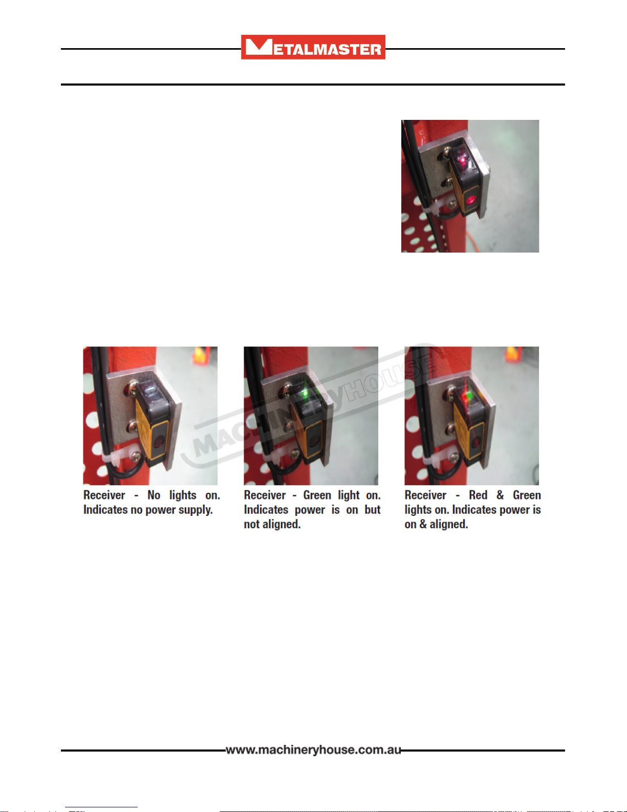
Receiver
e receiver has two lights on top of the unit. e receiver should have one green light on or a red
and green light on when all the sensors have been aligned correctly.
Note: No.1 receiver could be mounted top, middle or bottom on the guard.
e receivers are wired in series so No.1 receiver will have a green light on, indicating it has power.
When it is correctly aligned with its sender the red & green light will be on and it will send power
to No.2 receiver.
No.2 receiver will have a green light on and when that receiver has been correctly aligned with its
sender the red & green light will be on and it will send power to the No.3 receiver.
No.3 receiver is aligned using the same technique.
So when all 3 receivers are aligned correctly with their corresponding senders they should all have
red and green lights on top of each unit.
Page 14
Instructions Manual for MG-440 (S924A)
07/02/2018
15
OPERATION MANUAL
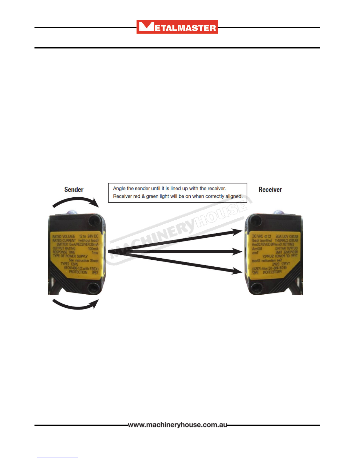
Alignment of Senders & Receivers
4.2 OMROM E3Z SAFETY SENSOR ALIGNMENT. CONT.
Ensure that the machine is level and all four leveling jacking bolts are correctly adjusted. Check the
rear guards are bolted tight and adjust the stabilizing feet to ground level to support the guards.
e sensors are sensitive to alignment so try to align as accurately as possible. If the sender is only
just aligned with the receiver, any vibration when cutting will stop the motor and the safety circuit
will have to be reset again.
Loosen the sender screws and angle the sender up until the receiver loses alignment.
Angle sender down until the receiver re-aligns and then loses alignment again.
Half way between these two positions is the most accurate alignment.
e sensors may also have to be angled sideways as well to get the best possible alignment. is may
involve packing individual brackets or sensors.
You can now reset the safety circuit & press the reset button
Aer a successful reset the light on the control panel will not be illuminated and the machine is
ready to operate.
Fig. 1
Page 15
Instructions Manual for MG-440 (S924A)
07/02/2018
16
OPERATION MANUAL
Fig. 4.1
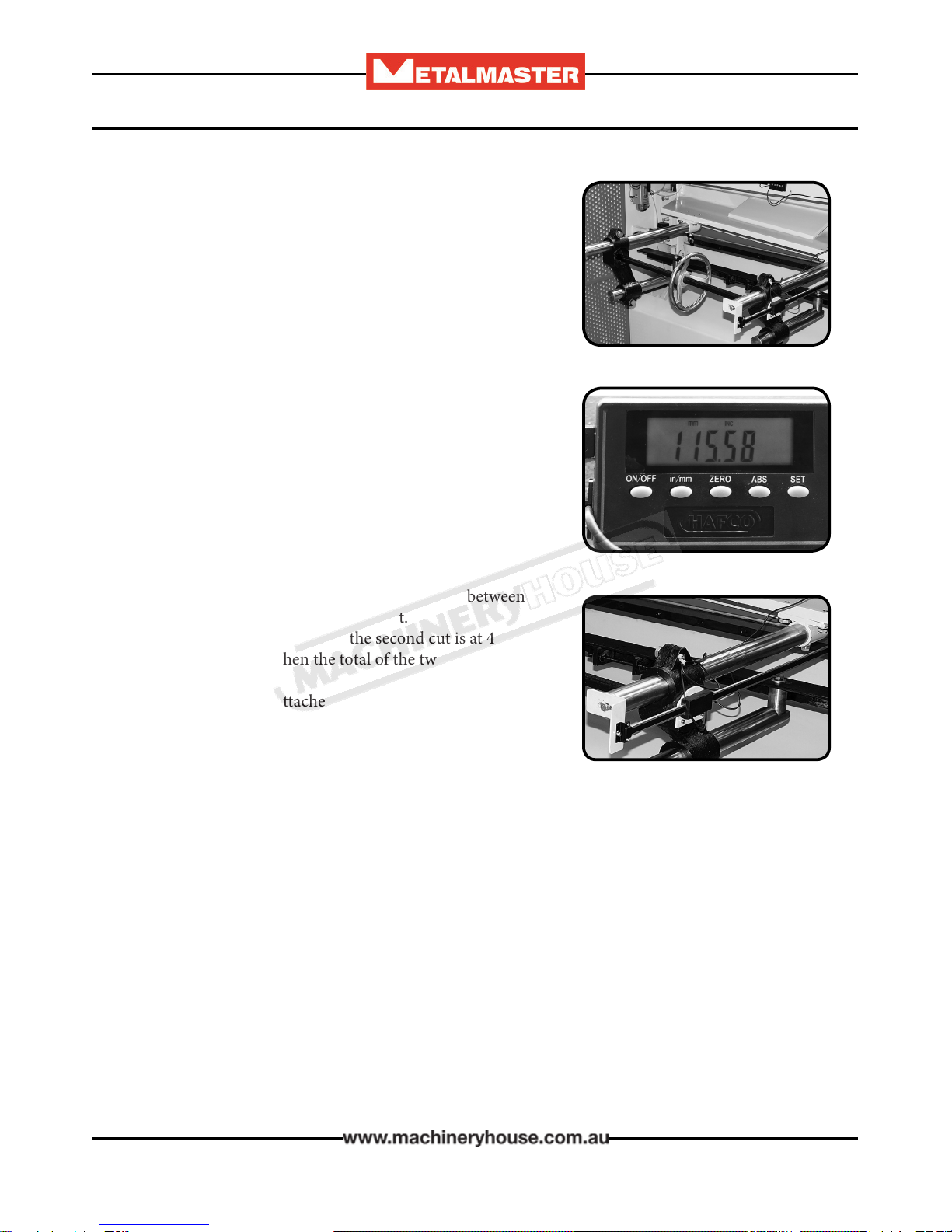
4.3 MANUAL BACK GAUGE.
e back gauge consists of a le and right hand shas tted
with a rack and pinion. Mounted on each sha is a sliding
block that slides along the rack sha carrying the back gauge.
e racks are connected by a sha and handwheel. When
turning the hand wheel the back gauge is moved in and out.
e sha can also be used for adjusting the synchronizing of
the two ends of the back gauge to keep them parallel.
e right rack sha is tted with a scale with graduations of
0.5mm. When installing the machine for the rst time or af-
ter grinding the blade, you should carefully adjust the “zero”
position,
e two sliding blocks are tted with clamping handles. Aer
the adjustment of the gauge distance, re-clamp the handles.
Digital Readout
Some machines are tted with a digital readout on the back-
gauge (Fig.4.2). e adjustment can be set using the display.
e display unit can be changed between inch or metric and
allows for “Zero” to be selected in any position.
It also has a button (ABS) which allows a switch between
absolute and incremental measurement.
E.G. First cut is at 100mm, and the second cut is at 400mm
when ABS is pressed then the total of the two is displayed as
“500”mm.
e digital display is attached to the right hand sha and does
not need to be reset as the scale can be “Zero” in any position.
Aer the adjustment of the gauge distance, re-clamp the
handles.
Fig. 4.2
4.4 COMMISSIONING CHECK LIST.
Before starting the machine the following checks must be carried out.
q Installation and machine preparation has been performed according to the manuals instructions.
q All grease nipple points have been lubricated.
q Electrical earth tted and power circuits, switches, and foot-pedal checked for any damage
q Setup rear sensors
q Check motor rotation.
q Test safety operation, E stop, rear sensors, stop button etc.
q Test all mechanical operation on the machine including blade and back gauge travel and limit
switch operation.
q Test cut material and check quality of cut
q Tools, equipment and personnel are clear of the machine.
q Operation Manual on how to operate the machine has been read.
Page 16
Instructions Manual for MG-440 (S924A)
07/02/2018

17
OPERATION MANUAL
5. OPERATION INSTRUCTIONS
5.1 PRE-OPERATIONAL SAFETY CHECK PRIOR TO OPERATING
Before operating the machine the rear safety beam guard needs to
be checked. Below are the steps that need to be followed.
1. Start machine as per instruction procedures
2. Stand outside rear safety gate & obstruct sensor (1)
3. Ensure machine has stopped and is disabled
4. Check your control: Warning light (A)
5. Press green reset button at the rear of electrical box image (C)
6. If red light on control panel is o continue to step 7
7. Repeat steps 1 to 6 for each sensor (2) & (3)
A: Basic Control - Light on
Emergency Stop Check,
B: Rear Guarding Sensors C: Guard Reset Button
1. Start machine as per instruction procedures
2. Press the emergency stop buttons on the control panel and front of the machine. (E)
3. Ensure the machine has stopped and is disabled
4. Reset emergency stop button by twisting the red dial. (D)
(Some models need guard to also be reset)
5. Repeat steps 1 to 4 for each emergency stop on your machine
E: Emergency Stop D: Guard Reset Button
(1)
(2)
(3)
Page 17
Instructions Manual for MG-440 (S924A)
07/02/2018

18
OPERATION MANUAL
5.2 STARTUP
Before starting the machine ensure that the manual has been read and understood.
1. Switch the isolating switch on (Fig 1.) e “Power On Light” (Fig.2) will be illuminated.
Fig 1.
12
3
4
56
1 Power ON Light
2 Illuminated Start Button
3 Electrics OFF
4 Continuous or Single cut
5 Emergency Stop
6Rear Safety Guard
2. If all the safety checks have been done then press the
“Start” button to energise the electrics. (Fig 2.)
Now the pedal can be depressed to start the cut
NOTE! e “Start Button” must be illuminated for the
pedal to operate.
Fig 2.
1
Page 18
Instructions Manual for MG-440 (S924A)
07/02/2018

19
OPERATION MANUAL
5.3 ADJUSTING OF THE BLADE GAP
Check the maximum cutting capacity of the guillotine..
is can be found on the specication plate on the ma-
chine. e capacity listed is for Mild Steel. Stainless steel
capacity can be found in the specication table in this
manual. (Page 4)
Check e Blade Gap Setting
e machine is supplied from the factory with the blade gap
set to the capacity of the machine.
NOTE! It is extremely important that the blade gap must be
reset to suit the thickness of the material every time the size
of the materials changes. Failure to do this could cause dam-
aged to the machine
e blade gap should be approximately 10% of the thickness
of the material.
E.G. 1mm material = 0.1mm Blade Gap
2mm material = 0.2mm Blade Gap
Adjusting the Blade Gap
Step 1. Isolate the machine from the power supply and
place a maintenance tag on the electrical cabinet.
Step 2. e 4 head bolts at both ends of the machine
should not be tightend up too tight. e gap should be
able to be adjusted with out undoing the bolts. If they
need to be loosened to adjust the blade gap, be sure they
are tightened only slightly. (Fig.5.3) Fig. 5.3
Step 3. Set the rapid blade adjustment to the correct gap.
Repeat the operation at the opposite end of the machine
to ensure that the blade is parallel. (Fig. 5.4)
Step 4. Re-tighten the head bolts at both ends of the ma-
chine. Do not over tighten the bolts as this can reduce the
set blade gap
Fig. 5.4
Page 19
Instructions Manual for MG-440 (S924A)
07/02/2018

20
OPERATION MANUAL
6.1 TYPE AND FREQUENCY OF INSPECTIONS
Inspection Period Responsibility
Lubrication of all grease points Daily Operator
Lubrication of slideways Weekly Operator
Guide surface of hold-down
plate Daily Operator
Gear and Rack of the Back
Gauge Monthly Operator
Bearing of the Main Sha 6 Month Planned Maintenance
Brass Bush for eccentric sleeve Daily Operator
Sha pin of the connecting rod Monthly Operator
Gearbox 6 Month Planned Maintenance
All Guards that protect against
physical damage Daily Operator
Machine xing bolts against
loosening Weekly Operator
Safety & limit switches against
loosening, or damage Weekly Operator
Terminal connections of the
electrical installation Annually Electrician
Fig. 5.4
6. MAINTENANCE
Page 20
Instructions Manual for MG-440 (S924A)
07/02/2018
This manual suits for next models
1
Table of contents
Other MetalMaster Power Tools manuals


Popular Power Tools manuals by other brands


Hubbell
Hubbell ANDERSON VC6-500-BP Service and operation manual

Matco Tools
Matco Tools MT2859 operating instructions

Ammann
Ammann ADS 70 Translation of the original operating instructions

Makita
Makita JN1601J instruction manual

Facom
Facom E.306-30D instruction manual

Metabo
Metabo BS 14.4 Original instructions


