MetalMaster HP-20PP User manual
OPERATION MANUAL
Edition No : HP-20PP-3
Date of Issue : 05/2020
Model. HP-20PP
Order Code P142
HYDRAULIC PRESS

2
OPERATION MANUAL
NOTE:
In order to see the type and model of the machine, please see
the specication plate. Usually found on the side or back of
the machine. See example (Fig.1)
Fig.1
HYDRAULIC PRESS
MACHINE
HP-20PP
MODEL NO.
SERIAL NO.
DATE OF MANF.
Note:
This manual is only for your reference. Owing to the continuous improvement of the
Metalmaster machine, changes may be made at any time without obligation or notice.
Please ensure the local voltage is the same as listed on the specication plate before
operating any electric machine.
Distributed by
www.machineryhouse.co.nz
MACHINE DETAILS

3
OPERATION MANUAL
C O N T E N T S:
1. GENERAL MACHINE INFORMATION
1.1 Specications................................................................ 4
1.2 Identication................................................................. 5
2. IMPORTANT INFORMATION
2.1 General Workshop Safety......................................... 6
2.2 Safe Operating Procedure for Hydraulic press.. 8
2.3 Lifting Instructions...................................................... 9
3. INSTALLATION
3.1 Assembly......................................................................... 10
3.2 Bleeding The Hydraulic System.............................. 13
3.3 Site Preparation............................................................ 13
3.4 Options For Mounting................................................ 13
4. OPERATION
4.1 Positioning the Bed..................................................... 14
4.2 Positioning the Ram.................................................... 14
4.3 Pressing Process........................................................... 15
5. MAINTENANCE
5.1 Inspection Schedule.................................................... 16
5.2 Troubleshooting........................................................... 16
5.3 Filling The Hydraulic Oil............................................. 17
Spare Parts.............................................................................. 18
Risk Assessment Sheets..................................................... 25

4
OPERATION MANUAL
Order Code P142
Model HP-20PP
Pressing Capacity (Tonne) 20
Hydraulic Ram Operation (Type) Manual-Hydraulic
Sliding Ram (left-right) (Yes/No) Yes
Width Between Front Posts (mm) 542
Width Between Side Posts (mm) 85
Table Top Opening - (Front to Back) (mm) 105
Ram To Table (Max.) (mm) 980
Piston Ram Stroke (mm) 185
Ram Diameter (mm) Ø48
Operating Pressure (p.s.i) 110 -120
Dimensions (W x D x H) (mm) 738 x 700 x 1790
Shipping Dimensions (W x D x H) (mm) Carton 1 1560 x 195 x 135 (80kg)
Shipping Dimensions (W x D x H) (mm) Carton 2 730 x 270 x 170 (35kg)
Nett Weight (kg) 112
1.1 SPECIFICATIONS
5
OPERATION MANUAL
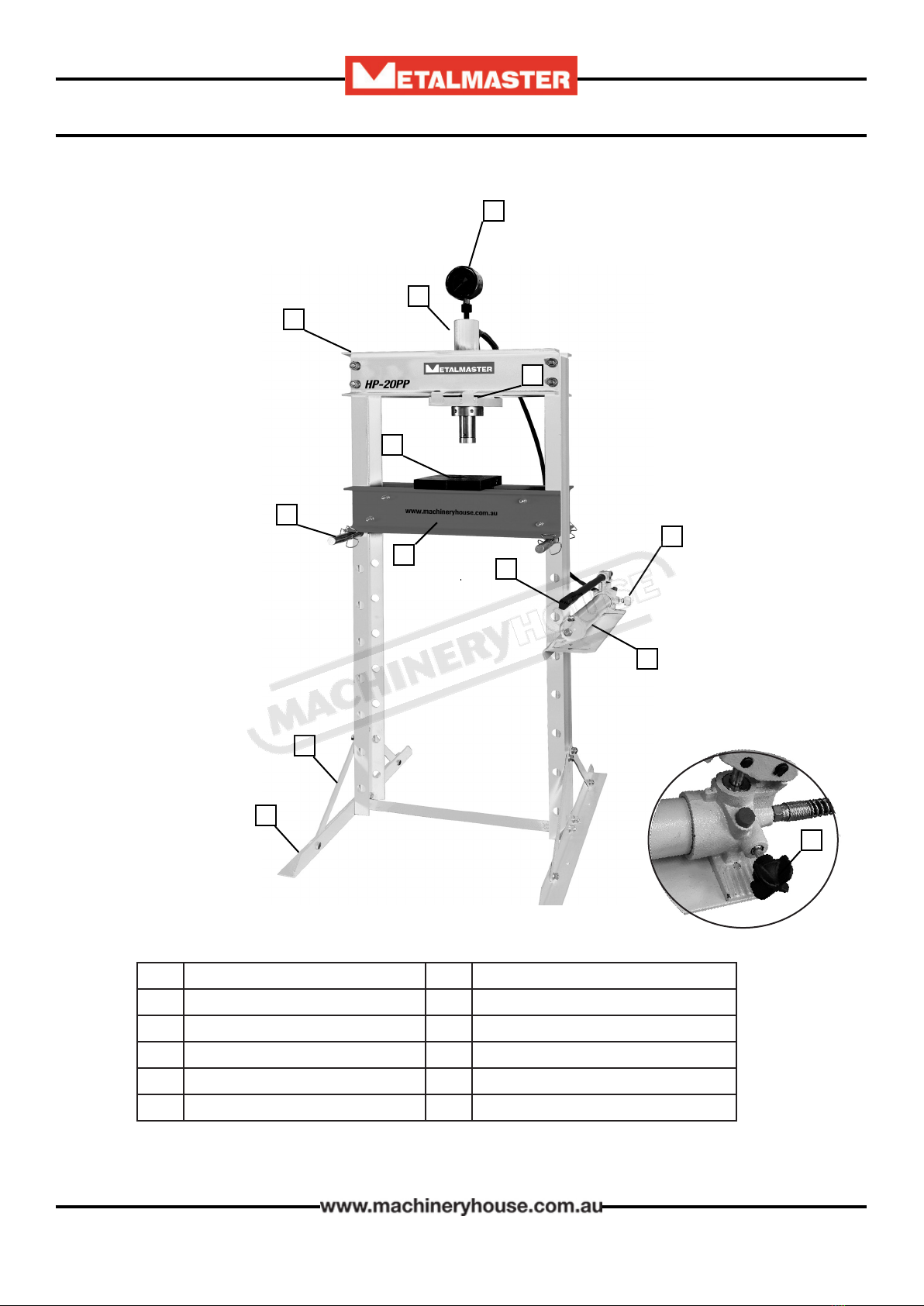
1.2 IDENTIFICATION
A
K
B
C
D
E
F
G
E
H
J
AMain Frame GHydraulic Pump Handle
BCylinder HPress Feet
CPressure Gauge IPress Feet Support Bars
DRam Baseplate JBed or Working Table
EPump Release Valve KSafety Pins with Retaining Clips
FHydraulic Pump LPressing Plates
I
L

6
OPERATION MANUAL
2.1 GENERAL SAFETY REQUIREMENTS
DO NOT use any machine unless you have read the manual or have been instructed in the use of
the machine in its safe use and operation
Safety glasses must be worn at
all times in work areas. Earmus
should be worn if the work area is
noisy.
Sturdy footwear must be worn
at all times in work areas.
Gloves should NOT be worn when
operating this machine
Long and loose hair must be
contained with a net or under a
hat
This manual provides safety instructions on the proper setup, operation, maintenance, and
service of this machine. Save this manual, refer to it often, and use it to instruct other operators.
Failure to read, understand and follow the instructions in this manual may result in serious
personal injury—including amputation, or death.
The owner of this machine is solely responsible for its safe use. This responsibility includes, but
is not limited to proper installation in a safe environment, personnel training and authorization
to use, proper inspection and maintenance, manual availability and comprehension, of the
application of the safety devices, integrity, and the use of personal protective equipment.
The manufacturer will not be held liable for injury or property damage from negligence,
improper training, machine modications or misuse.
WARNING
CHECK DAMAGED PARTS. Regularly inspect
the machine for any condition that may aect
the safe operation. Immediately repair or re-
place damaged or parts that are incorrectly
tted before operating.
OWNER’S MANUAL. Read and understand this
owner’s manual before using the machine.
TRAINED OPERATORS ONLY. Operators that
have not been trained have a higher risk of
being seriously injured. Only allow trained or
supervised people to use this machine. When
the machine is not being used, disconnect the
power, to the machine to prevent unautho-
rized use—especially around children. Make
the workshop safe.

7
OPERATION MANUAL
WEARING PROPER APPAREL Do not wear
clothing, apparel or jewelry that can become
entangled in moving parts. Always tie back
or cover long hair. Wear non-slip footwear to
avoid accidental slips, which could cause loss of
operating control.
HEARING PROTECTION. Always wear hearing
protection when operating or observing loud
machinery. Extended exposure to this noise
without hearing protection can cause perma-
nent hearing loss.
USE CORRECT TOOL FOR THE JOB. Only use
this tool for its intended purpose. Do not force
the machine or its attachments to do a job for
which they were not designed. Never make
unapproved modications. Modifying the ma-
chine or using it dierently than intended may
result in malfunction or mechanical failure that
can lead to personal injury or death!
AWKWARD POSITIONS. Keep proper footing
and balance at all times when operating the
machine. Do not overreach! Avoid awkward
hand positions that make operating control
dicult. This could increase the risk of acciden-
tal injury.
FORCING MACHINERY. Do not force the ma-
chine. It will do the job safer and better at the
rate for which it was designed.
NEVER STAND ON MACHINE. Serious injury
may occur if the machine is tipped or if crush
points are unintentionally contacted
STABLE MACHINE. Unexpected movement
during operation greatly increases risk of injury
or loss of control. Before using the machine ,
verify that it is stable
UNATTENDED OPERATION. To reduce the risk
of accidental injury, never leave the machine in
use while unattended.
MAINTAIN WITH CARE. Follow all maintenance
instructions and lubrication schedules to keep
the machine in good working condition. A
machine that is improperly maintained could
malfunction, leading to serious personal injury
or death.
CHILDREN & BYSTANDERS. Keep children and
bystanders at a safe distance from the work
area. Stop using machine if they become a
distraction.
2.1 GENERAL WORKSHOP SAFETY Cont.
Warning: Crush Points can occur
between the Ram and the workpiece
or between the workpiece and the
table.
8
OPERATION MANUAL
2.2 SAFE OPERATING PROCEDURE FOR HYDRAULIC PRESS
DO NOT use this machine unless you have been instructed in its safe use
and operation and have read and understood this manual.
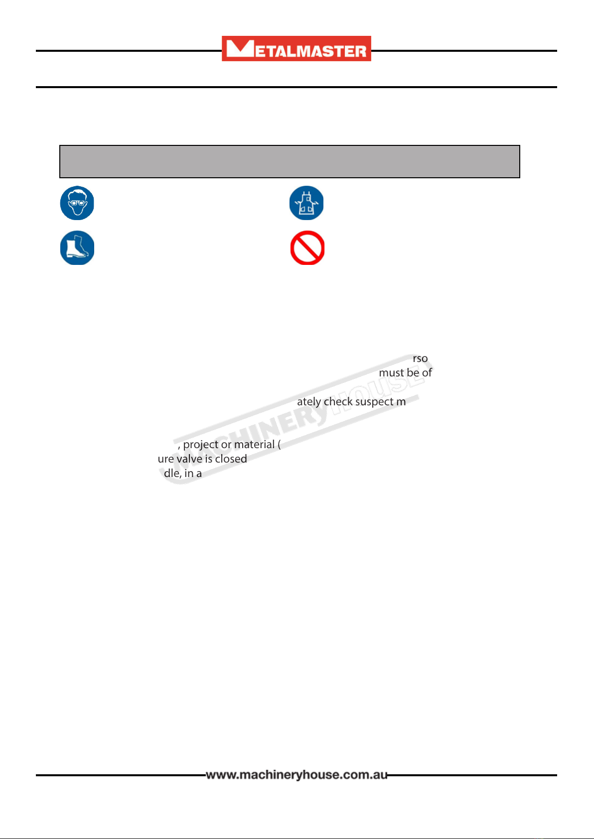
Safety glasses must be worn at
all times in work areas.
Close tting protective clothing or
overalls are encouraged
Appropriate protective footwear
with substantial uppers must be
worn.
Rings and jewelery must NOT be
worn in the workshop
PRE-OPERATIONAL SAFETY CHECKS
1. Ensure you are familiar with the operation of the hydraulic press.
2. Check for any hydraulic uid leaks.
3. The press table must be clean and steel weights are at and secure on press table.
4. Any forming die or cutting die must be inspected for safe use i.e. no cracks.
5. Ensure safety glasses or goggles are available and are worn by all persons in the vicinity.
6. Any test piece, project or material (work piece) to be pressed must be of an appropriate
thickness and safe to use on this equipment.
7. Faulty equipment must not be used. Immediately check suspect machinery.
OPERATIONAL SAFETY CHECKS
1. Place your test piece, project or material (work piece) securely on the press table.
2. Ensure the pressure valve is closed before operation.
3. Use the press handle, in a pumping action, to slowly lower the press hammer.
4. Use your shoulder muscles when operating – NOT your lower back.
5. Keep hands and ngers away from all clamping and moving parts.
6. Carefully and accurate alignment the press hammer face with the work piece for even force
to be applied.
7. Once the press hammer makes contact with the work piece, closely watch the PSI gauge
and note the pressure applied.
8. Once the work piece is pressed suciently, release the hammer pressure at the release
valve.
9. DO NOT apply excessive force with the press.
AFTER OPERATION COMPLETED
1. After use, clean the press down and place any tools and equipment in the appropriate
storage area – including the press handle.
2. Place all scrap or waste in the appropriate bin.
POTENTIAL HAZARDS
Beware of high forces applied Eye injuries – ying or shattering objects
Pinch and squash Laceration injuries
Potentially uneven forces being applied to the work piece

9
OPERATION MANUAL
2.3 LIFTING INSTRUCTIONS
Make sure that a crane or forklift with sucient capacity is available to unload the machine from
the vehicle. Ensure access to the chosen site is clear and that doors and ceilings are suciently
high and wide enough to receive the machine.
The machine is heavy and will require two or more to lift and assemble.
When lifting the machine only certied lifting slings
should be used. (Fig.2.1)
Ensure that when lifting, the machine does not tip over.
Check that the lifting slings do not interfere with the
hydraulic pipes.
Failure to follow these instructions could cause damage
to the machine
LIFTING POINTS
Fig. 2.1

10
OPERATION MANUAL
The position where your machine is operated is important for safe operation and the longevity
of its components. For best results, operate this machine in a dry environment that is free from
excessive moisture, hazardous chemicals, airborne abrasives, or extreme conditions.
Extreme conditions for this type of machinery are generally those where the environment is
subject to vibration, shocks, or bumps.
Children or untrained people may be seriously injured by this machine. Only install in an
access restricted location.
Lighting around the machine must be adequate enough that operations can be performed
safely.
Consider the largest size of workpiece that will be processed through this machine and provide
enough space around the machine for adequate operator material handling or the installation
of auxiliary equipment.
3. INSTALLATION
3.1 ASSEMBLY
Ensure the press and its components suered no damage during transit and that all the parts
are present. Should any loss or damage become apparent, please contact your local dealer
immediately.
IMPORTANT: Due to the weight of the press components, we recommend that you get
assistance during assembly.
IMPORTANT: Do not locate your press where it will be open to the elements, as severe weather
conditions will damage the hydraulic parts.
Use the spare part exploded drawing on page 23 as your guide to assemble.
Lay all parts and assemblies out in front of you before beginning.
Loosely attach all frame parts rst then once the frame is all assembled tighten all the fasteners.
The following procedure is recommended:
1. Attach one base section (21) to a main
post (20) and lower cross member (26)
using bolts M12 x 35mm (25), washers
M12 (22), spring washers M12 (23) and
nuts M12 (24), then attach the other
post to the opposite side of the lower
cross member, using the same fasteners
as above. (Fig.3.1)
2. Attach the 4 x Support bars (34) to the
base section (21) and the main posts (20)
using bolts M10 x 25mm (33), washers
M10 (14), spring washer M10 (15) and
nuts M10(16). (Fig.3.1) Fig.3.1
11
OPERATION MANUAL
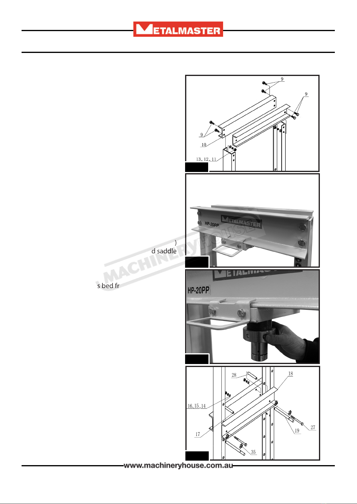
Fig.3.2
3. Put the press frame in an upright position,
attach the 2 x upper cross beams (10) to left
and right main posts (20) using bolts M16 x
35 (9), M16 washers (13), M16 spring
washers (12) and M16 nuts (11). The upper
cross beam with the Metalmaster logo is to
be facing the front of the press. (Fig.3.2)
4. Tighten all frame bolts
5. Attach the sliding plate (7) to the upper
cross beams, with the handle hook side
facing the front of the press. Using the 4 x
M8 x 20 bolts, at and spring washers.
(Fig.3.3)
6. Screw the upper round nut (6) onto the ram
(3), insert the ram into the hole in the under
plate (7), then screw the under round nut (8)
onto the ram and attach the serrated saddle
(5) to the ram. (Fig.3.4)
7. Join the two press bed frame (18) together
by inserting the four bolts M10 x 140 (27)
through the bushings (28) and the holes in
the bed frames, then secure the four bolts
by tighten the M10 washer (14), M10 lock
washer (15) and M10 nut (16) on it. (Fig.3.5)
8. Insert bed frame pin (19) into the holes in
the posts, then insert the joined press bed
frame (18) into press frame and onto bed
frame pin. Use the retaining clip (35) to
secure the pins in place.
Fig.3.5
Fig.3.3
Fig.3.4

12
OPERATION MANUAL
Fig.3.6
8. Attach the setting plate (31) to the right
hand post using bolts M12 x 30 (36), M12
washers (22), M12 lock washers (23) and
M12 nuts (24), then secure the pump
assembly using the M8 x 16 screws (30) and
M8 washers (29), and then insert the handle
to the handle bracket (Fig.3.6)
9. Assemble the pressure gauge to the
pressure gauge connection nut (R13) and
nylon ring (2) which are on the top of ram
(3). Use PTFE sealing tape to seal the threads
(Fig.3.7)
10. Unfasten the protective hose caps and
screw the hose onto the threaded
connection of the hydraulic ram.
11. With the ram in the fully retracted position,
unscrew the ller plug on top of the
cylinder and check that the pump is lled
with oil up to the bottom of the thread.
(Fig.3.6)
Fig.3.7
Fig.3.8
Filler Cap
R13

13
OPERATION MANUAL
3.4 OPTIONS FOR MOUNTING
The machine is best mounted on a concrete slab.
Masonry anchors with bolts are the best way to anchor the
machinery, because the anchors sit ush with the oor sur-
face, making it easy to unbolt and move the machine later, if
needed. (Fig. 3-8)
3.3 SITE PREPARATION
When selecting the site for the machine, consider the largest size of workpiece that will be
processed through the machine and provide enough space around the machine for operating
the machine safely. Consideration should be given to the installation of auxiliary equipment.
Leave enough space around the machine to open or remove doors/covers as required for the
maintenance and service as described in this manual.
It is recommended that the machine is anchored to the oor to prevent tipping or shifting. It
also reduces vibration that may occur during operation.
3.2 BLEEDING THE HYDRAULIC SYSTEM
Before using the press, any air needs to be
removed from the system.
To Bleed the system:
1. Opening the release valve by turning it
anticlockwise
2. Pump the handle of the pump around ten
full strokes to eliminate any air bubbles.
(Fig.3.9)
3. Close the release valve by turning it clock
wise and start to pump. If the pressing
seems spongy then repeat the process.
• The press is now ready for use.
Fig. 3.10
Fig.3.9
Release
Valve

14
OPERATION MANUAL
4. OPERATION
IMPORTANT: Due to the weight of the bed, we recommend that you get assistance from
another person when adjusting the bed height.
1. Position the bed at the desired height, so that it will be as close as possible to the ram when
the workpiece is mounted on it.
2. Raise one side of the bed and insert a supporting pin into the next locating hole.
3. Repeat at the other end to level the bed.
4. Repeat until the bed is at the desired height, with the supporting pins fully ‘home’.
5. Replace the safety clips on both end of the supporting pins.
The bed height should only be raised or lowered one hole at a time,
working alternately from one side and then the other, failure to work in this way may cause the
bed to fall and cause injury to the operator
4.1 POSITIONING THE BED
Fig.4.1
4.2 POSITIONING THE RAM
The press is designed with a quick action
method when moving the ram. It can be
quickly positioned in either direction as re-
quired by sliding the ram baseplate along the
cross-beam using the handle.
The head is secured when pressure is applied
to the ram.
Always position the ram
directly above the workpiece.
NOTE:
Always make sure you are pressing with the whole ram.
Center the ram over the work, do not press with only the
edge of the nose piece. This can cause injury by ejecting
the part, or damage to the ram.
Incorrect Correct

15
OPERATION MANUAL
4.3 PRESSING PROCESS
1. Place the workpiece on the bed. It must be
completely stable and supported by packing
or shims where required. Steel pressing plates
are supplied, (Fig.4.2) which locate on the
bed in either at or vertical position. Place the
workpiece on a combination of these to give
it stability.
NOTE: Any packing pieces or shims used MUST
be capable of withstanding the pressure that will
be brought to bear, and MUST be of sucient
size with sucient surface area, so as to avoid the
possibility of slipping or springing out. Mating
surfaces MUST be horizontal so that the force
being exerted will NOT be at an angle.
2. Close the release valve by turning it clockwise
until tightly closed. (Fig. 4.3)
3. Pump the handle to bring the ram very lightly
into contact with the workpiece.
4. Position the workpiece or slide the ram to
one side so that the desired point of contact
is directly beneath the centre of the ram
Fig.4.2
5. When satised that the workpiece is correctly aligned and is completely stable in that
position, slowly pump the handle so that the ram begins to exert pressure on the work
piece. Continue to pump the handle whilst standing to the side. Do NOT stand directly
in front of the work, and constantly monitor the process, ensuring the ram and work
remain completely in line and there is no risk of slipping.
6. When the process is complete, turn the release valve anticlockwise in small increments to
release ram pressure and allow removal of the workpiece.
Do not exceed the rated capacity of the press. Do not allow any
person who is inexperienced in the use of hydraulic presses, to use the press unless they are
under direct supervision
Fig.4.3
Release
Valve

16
OPERATION MANUAL
5. MAINTENANCE
• A visual inspection must be made before each use of the press, checking for leaking
hydraulic uid and damaged, loose, or missing parts.
• Owners and/or users should be aware that repair of this equipment requires specialized
knowledge and facilities. It is recommended that a thorough annual inspection of the press
be made and that any defective parts be replaced with genuine Metalmaster parts.
• Any press which appears to be damaged in any way, is found to be badly worn, or operates
abnormally SHOULD BE REMOVED FROM SERVICE until the necessary repairs are made.
• If the press is not to be used for any length of time, store it with the ram retracted and the
operating handle in the lowered position to protect the moving parts.
5.1 INSPECTION SCHEDULE
• Check the press frame to make sure all bolts are tight and inspect for cracked welds, bent,
loose or missing parts.
• Check the hydraulic connections for leaks. Replace or properly repair any damaged or
leaking hydraulic components before using. In the event of leaking seals, oil can be topped
up via the plug on the end of the pump. Oil should be level with the bottom of the hole. If
necessary top up with hydraulic oil, This task is carried out with the ram fully retracted.
• If any rust is apparent it must be removed completely and the paint restored
Problem Probable Cause Remedy
Pump unit will not work Dirt on the valve seat/worn
seals
Bleed pump unit or have unit
overhauled with new seals
Pump will not produce
pressure. Pump feels hesitant
under load. Pump will not
lower completely
Air-lock
Open the release valve and
remove the oil ller plug.
Pump the handle a couple
of full strokes and close the
release valve.
Replace the ller plug.
Pump will not deliver
pressure
Reservoir could be overlled
or have low oil level
Check oil level by removing
the ller plug and topping up
to the correct level.
Pump feels hesitant under
load
Pump cup seal could be worn
out Have the cup seal replaced.
Pump will not lower
completely Air-lock Release air by removing the
ller plug
5.2 TROUBLESHOOTING
17
OPERATION MANUAL
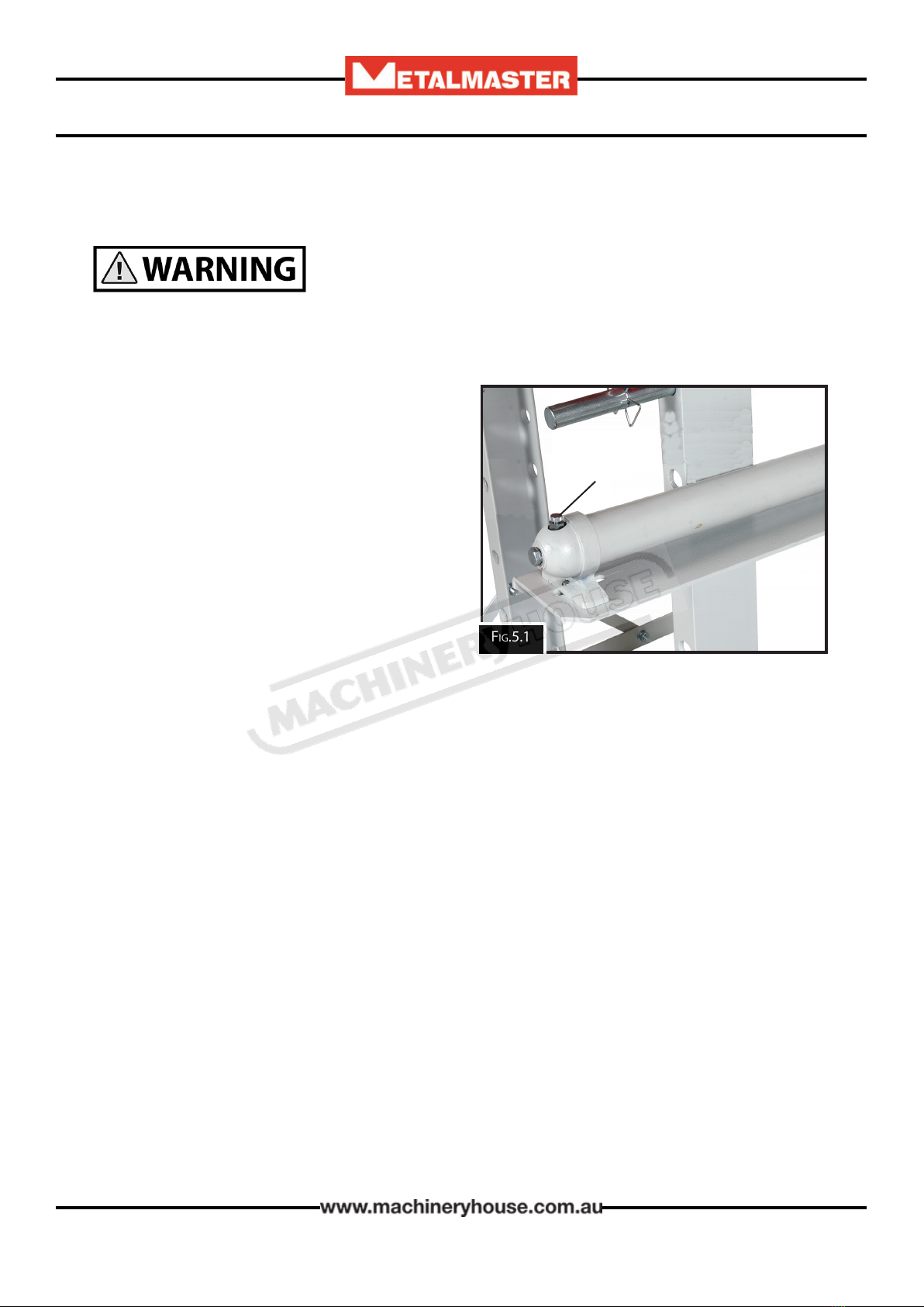
5.3 FILLING THE HYDRAULIC OIL
When lling the oil the ram must be in the FULLY UP POSITION
before any lling of the oil takes place. Failure to do so will cause overowing of the oil, creating
a slip hazard.
Checking the hydraulic oil:
The hose must not be remove when checking
the oil. To check or ll the pump, open the oil
ller cap on the top of the reservoir. (Fig.5.1).
The oil should be lled to the bottom of the
thread. If the oil is not adequate, ll with 32#
hydraulic oil as necessary. Once lled, then
replace the ller cap, and bleed the air from the
hydraulic system as described on page 13.
Metalmaster have technical support engineers
available for service. Fig.5.1
Filler Cap

18
OPERATION MANUAL
CONTENTS
Pump Spare Parts Diagram.................................... 19
Pump Spare Parts List.............................................. 20
Ram Spare Parts Diagram...................................... 21
Ram Spare Parts List................................................. 22
Press Spare Parts Diagram..................................... 23
Press Spare Parts List................................................ 24
SPARE PARTS SECTION
The following section covers the spare parts diagrams and lists that were current at the time
this manual was originally printed. Due to continuous improvements of the machine, changes
may be made at any time without notication.
HOW TO ORDER SPARE PARTS
1. Have your machines model number, serial number & date of manufacture
on hand, these can be found on the specication plate mounted on the machine
2. A scanned copy of your parts list/diagram with required spare part/s
identied
3. Go to www.machineryhouse.com.au/contactus and ll out the enquiry form attaching a
copy of scanned parts list.
Edition No : HP-20PP-3
Date of Issue :05/2020
Model. HP-20PP
Order Code P142
HYDRAULIC PRESS

19
OPERATION MANUAL
HP-20PP PUMP SPARE PARTS DIAGRAM
20
OPERATION MANUAL
No. Description Qty No. Description Qty
P01
P02
P03
P04
P05
P06
P07
P08
P09
P10
P11
P12
P13
P14
P15
P16
P17
P18
P19
P20
Pump
Filter
O-ring
Reservoir
Tie rod
Screw
Screw
O-ring
Pump foot
Steel ball
O-ring
Release valve
Hydraulic hose
Coupler
Dust cap
Steel ball
Base of steel ball
Spring
Screw
O-ring
1
1
2
1
1
1
1
1
1
3
1
1
1
1
1
1
1
1
1
2
P21
P22
P23
P24
P25
P26
P27
P28
P29
P30
P31
P32
P33
P34
P35
P36
P37
P38
P39
P40
Screw
Cap
Steel ball
Nylon ring
Sealing ring
O-ring
Nylon ring
Base of pump core
O-ring
Nylon ring
Pump core
Pin
Retaining ring
Pin
Base of handle
Handle
Handle sleeve
Screw
Nylon ring
Spring
1
1
1
1
1
1
1
1
1
1
1
1
2
1
1
1
1
1
1
1
HP-20PP PUMP SPARE PARTS LIST
This manual suits for next models
1
Table of contents
Other MetalMaster Power Tools manuals


