Metasys ET Series User manual
Fire Initiating Devices and Notification Appliances Technical Manual 408
Notification Appliances Section
Technical Bulletin
Issue Date 1095
© 1995 Johnson Controls, Inc. 1
Code No. LIT-408195
Introduction Page 3
●
General Description 3
Installation Procedures 10
●
Mounting 12
●
Wiring Installation Guidelines 21
●
Limitations 24
ET Series Speakers and Strobe Speakers

2 Notification Appliances—ET Series Speakers and Strobe Speakers

Notification Appliances—ET Series Speakers and Strobe Speakers 3
Introduction
The ET series speakers and strobe speakers are UL Listed under Standard 1971 for
signaling devices for the hearing impaired and UL Standard 1480 for speaker appliances.
These speakers and strobe speakers are manufactured by Wheelock for use with Johnson
Controls systems.
The ET series is designed for multiple power requirements with high dBA output at each
power tap. All ET models offer a choice of field selectable taps: 1/8 to 8 watts for either
25 VRMS or 70 VRMS audio systems. The ET series design incorporates a high
efficiency speaker for maximum output at minimum power across a frequency range of
400 to 4000 Hz and features a sealed back construction for extra protection and improved
audibility.
All inputs are compatible with standard reverse polarity supervision of Notification
Appliance Circuit (NAC) wiring by a Fire Alarm Control Panel (FACP).
The optional strobe for the ET series speakers incorporates a xenon flashtube with solid-
state circuitry enclosed in a rugged LEXAN®lens to provide maximum reliability for
effective visible signaling. The strobe speakers are available with a choice of four UL
Listed strobe options: series LS, LSM, MS, and IS. (Refer to the LS, LSM, MS, and IS
Series Strobe Signals Technical Bulletin for specific information regarding these strobe
signals.) All models are UL Listed for indoor use. The LS, MS, and IS models are listed
for ceiling or wall mount using the backboxes specified in this document. The LSM
model is listed for wall mount only. (See the Mounting section of this document.)
Figure 1: Dimensions
Note: In order to ensure proper operation, this product should be applied as specified
in the applicable National Fire Protection Association (NFPA) codes and in
compliance with its UL listing.
General
Description
ET-1080
ET-1070
3/8 in.
3-3/8 in. s
q
.
5-3/8 in. s
q
.
F
I
R
E
2-7/16 in.
3 in.
ET-1090
et_1
2-7/16 in.
13/32 in.
3 in.
3-3/8 in. s
q
.
FIRE
7-3/8 dia.
ET-1010
1-15/16 in.
1-7/8 in.
Max.
3-3/8 in. s
q
.
4-3/8 in. s
q
.
2-7/16 in.
3 in.
Max.
3-3/8 in. s
q
.
5-7/16 in. s
q
.
F
I
R
E
1in.

4 Notification Appliances—ET Series Speakers and Strobe Speakers
!
WARNING: Personal injury hazard. Failure to follow these directions
may result in the failure of the device to report an alarm or
trouble condition.
Johnson Controls is not responsible for devices that have been improperly installed,
tested, or maintained by others.
ET-1010 speakers (without a strobe) are UL Listed for indoor/outdoor use with a
temperature range of -31 to 150°F (-35 to 66°C) with a maximum relative humidity of
95%. All other models are UL Listed for indoor use with a temperature range of 32 to
120°F (0 to 49°C) and a maximum relative humidity of 85%.
The speakers and strobe speakers operate on Full-Wave Rectified (FWR), regulated
(filtered) DC voltage as well as unregulated (unfiltered) DC. Performance ratings are
based on nominal input voltages 24 VDC
(20 to 31 VDC).
The frequency range of the speakers is 400 to 4,000 Hz. Operate the ET-1010 speakers
only within the specified voltage range for rated performance and endurance.
All strobe models are designed to flash as specified with continuous nominal applied
voltage. The flash rate for the strobe is approximately one flash per second at nominal
voltage. Strobes are not designed to be used on coded systems in which the applied
voltage is cycled on and off.
All candela (cd) ratings represent effective intensity based on UL 1971.
This equipment has been tested and complies with the limits for a Class B digital device,
pursuant to Part 15 of the FCC rules. These limits are designed to provide reasonable
protection against harmful interference in installations. This equipment generates, uses,
and radiates radio frequency energy. If not installed and used in accordance with the
instructions, this equipment may cause harmful interference to radio communications.
However, there is no guarantee that interference will not occur in a particular installation.
If this equipment does cause harmful interference to radio or television reception, which
can be determined by turning the strobe and/or audible equipment off and on, the user is
encouraged to try to correct the interference by one or more of the following measures:
1. Reorient or relocate the receiving antenna.
2. Increase the separation between the equipment and receiver.
3. Consult the dealer or an experienced radio/TV technician for help.

Notification Appliances—ET Series Speakers and Strobe Speakers 5
!
CAUTION: Equipment damage hazard. Although UL testing has
verified these products function at 80% of their minimum
rating and 110% of their maximum rating, Johnson Controls
recommends that the voltage applied to these products be
within their rated input voltage range. The application of
improper voltage may result in degraded operation or damage
to these products.
!
CAUTION: Equipment damage hazard. Only the ET-1010 model is
suitable for outdoor use.
To verify that the signaling device is operating at rated voltages, determine the voltage
drop caused by the resistance of the Notification Appliance Circuit (NAC) wiring. Then,
subtract this voltage from both the maximum and minimum power supply and battery
voltages.
Table 1: ET Series Speakers and Strobe Speakers Specifications
Speaker Strobe
Model dBA at 10 Feet Input Strobe Mounting
Number Per UL 14804Voltage Candela Options3
(Rated Watts) (VDC) (cd)
1/8 1/4 1/2 1 2 418 Min Nom Max
ET-1010-R 78 81 84 87 90 93 96 ---- ---- ---- ---- E, F, G, H
ET-1070-R 78 81 84 87 90 93 96 ---- ---- ---- ---- A, D
ET-1080-R 78 81 84 87 90 93 96 ---- ---- ---- ---- C, D
ET-1090-W 78 81 84 87 90 93 96 ---- ---- ---- ---- B
ET-1070-LS-24-VFR 78 81 84 87 90 93 96 20 24 31 15 A, D
ET-1070-LSM-24-VFR 78 81 84 87 90 93 96 20 24 31 152A, D
ET-1070-MS-24-VFR 78 81 84 87 90 93 96 20 24 31 30 A, D
ET-1070-IS-24-VFR 78 81 84 87 90 93 96 20 24 31 75 A, D
ET-1080-LS-24-VFR 78 81 84 87 90 93 96 20 24 31 15 C, D
ET-1080-LSM-24-VFR 78 81 84 87 90 93 96 20 24 31 152C, D
ET-1080-MS-24-VFR 78 81 84 87 90 93 96 20 24 31 30 C, D
ET-1080-IS-24-VFR 78 81 84 87 90 93 96 20 24 31 75 C, D
ET-1090-LS-24-CFW 78 81 84 87 90 93 96 20 24 31 15 B
ET-1090-MS-24-CFW 78 81 84 87 90 93 96 20 24 31 30 B
ET-1090-IS-24-CFW 78 81 84 87 90 93 96 20 24 31 75 B
Notes: 1. The 4 watt rating is only available with 70 VRMS input.
2. The 15 cd models are listed at 15 cd and meet the Americans with Disabilities Act (ADA)
requirement of 75 cd on the axis.
3. Refer to Figures 3 through 10 in the
Mounting
section of this document.
4. UL 1840 measures dBA sound power levels in a reverberant test room.
Table 2: Strobe Current Requirements (amperes)
Rated Average
Current Rated Peak Current Rated Inrush Current

6 Notification Appliances—ET Series Speakers and Strobe Speakers
Voltage LS MS LSM IS LS MS LSM IS LS MS LSM IS
20 VDC 0.080 0.135 0.115 0.240 0.160 0.288 0.250 0.500 0.210 0.280 0.225 0.650
24 VDC 0.080 0.135 0.115 0.225 0.190 0.296 0.260 0.450 0.250 0.280 0.270 0.660
31 VDC 0.080 0.135 0.115 0.195 0.210 0.296 0.260 0.370 0.320 0.300 0.360 0.880
20 VFWR* 0.080 0.135 0.125 0.240 0.210 0.390 0.350 0.700 0.320 0.390 0.315 0.920
24 VFWR* 0.081 0.135 0.125 0.225 0.216 0.390 0.365 0.640 0.380 0.390 0.380 0.930
31 VFWR* 0.091 0.135 0.125 0.195 0.240 0.390 0.365 0.520 0.450 0.420 0.500 1.25
* All VFWR voltages are measured with a DC voltmeter. Multiply VFWR voltage by 1.11 to convert
values to VRMS.
Note: VDC is the voltage provided by a filtered (regulated) power supply. VFWR is
the voltage provided by an unfiltered (unregulated) full-wave rectified power
supply.
Ensure that the total current required by all the strobe devices connected to the system’s
primary and secondary power sources and NACs does not exceed the power supply’s
rated current.
Also ensure that the total wattage required by all the speakers connected to a system audio
amplifier and the speaker NAC control device does not exceed the power supply’s rated
current.
!
WARNING: Personal injury hazard. Exceeding the power supply’s
rated current could result in the loss of power and failure to
alert occupants during an emergency.
To calculate the total strobe current:
1. Use Table 2 to determine the highest value of rated average current for an individual
strobe.
2. Add this value to the total values of the strobes on the circuit.
3. Add the current for any other devices powered by the same source, including any
required safety factors.
Note: Calculate the total audible signal current in the same manner based on the input
voltage and the selected wattage of each individual speaker.
Verify electrical ratings specified in Tables 1 and 2 to ensure proper electrical input.
Verify speaker wires are only connected to speaker terminals and strobe wires are only
connected to strobe terminals. Verify wiring at the panel, power supply, and/or NAC
control point is correct.
!
CAUTION: Equipment damage hazard. Improper electrical input may
damage the device or cause it to malfunction.
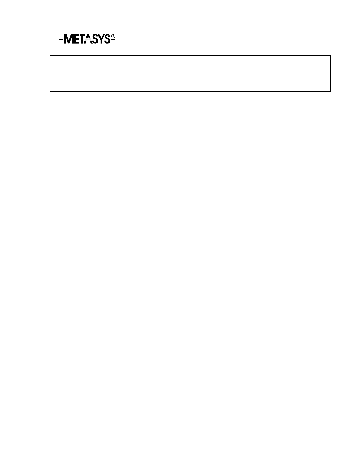
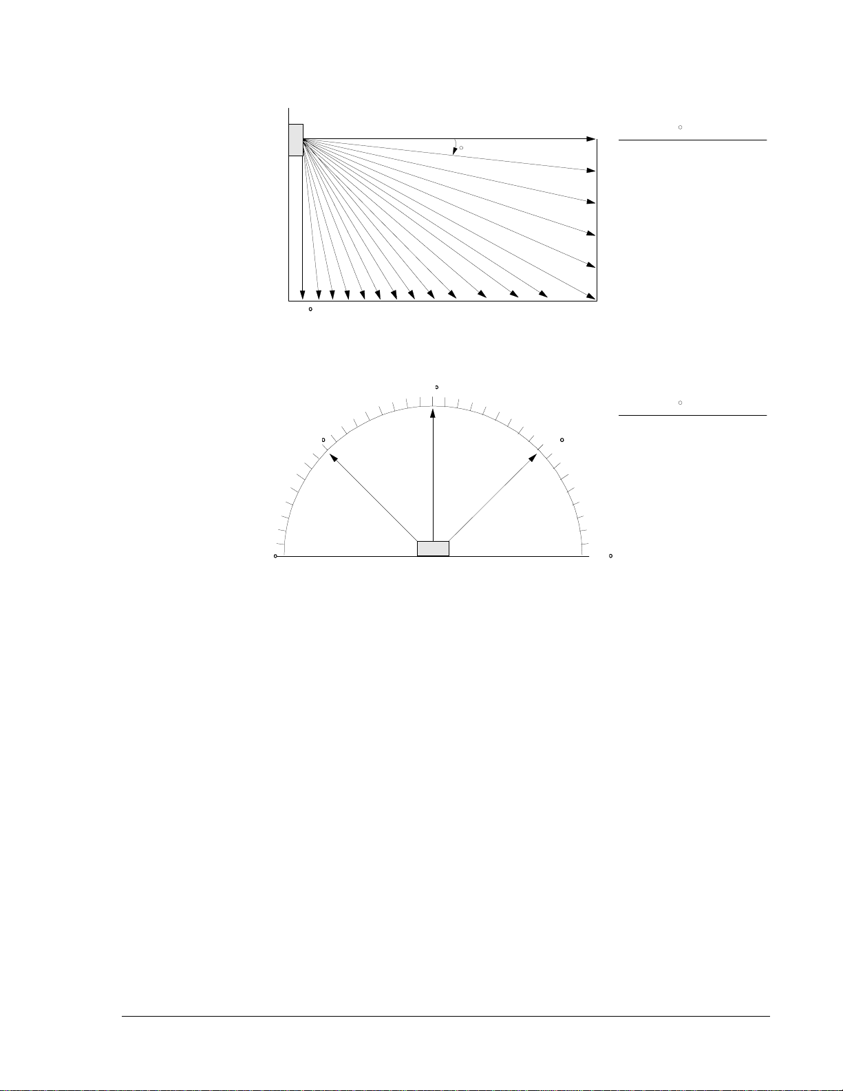
UL 1971 requires a polar light distribution pattern to enhance the likelihood of alerting
hearing impaired individuals throughout an area. Figure 2 illustrates the way the standard
measures light intensity, both horizontally and vertically. Tables 3 and 4 list the UL
minimum requirements and the actual value of the light intensity of the strobe signal.
Total Current
Light Distribution
Notification Appliances—ET Series Speakers and Strobe Speakers 7
Figure 2: Light Distribution Comparison
lightdis.drw
Wall Mount Horizontal Light Distribution
Wall
Li
g
ht
90
45
0
-90
-45
Zero Axis
Wall
Floor
0
5
10
15
20
25
90
85 80 75 70
65 60
55 50
45 40 35 30
Wall Mount Vertical Light Distribution
De
g
rees
Percent
of Rated
Li
g
ht Output
100
90
65
48
34
27
22
18
16
15
13
12
12
12
0
5-30
35
40
45
50
55
60
65
70
75
80
85
90
De
g
rees
Percent
of Rated
Li
g
ht Output
100
90
75
55
45
40
35
35
30
30
25
25
0
5-25
30-45
50
55
60
65
70
75
80
85
90
8 Notification Appliances—ET Series Speakers and Strobe Speakers
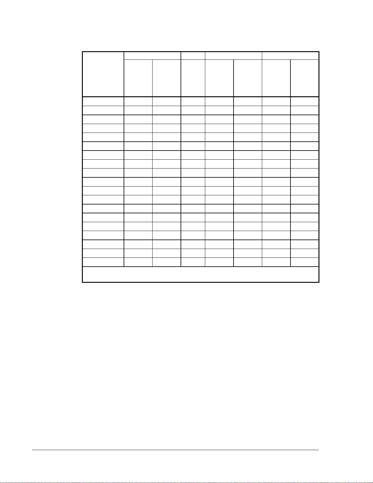
Table 3: Horizontal Plane Light Distribution
Horizontal 15 cd 15 cd* 30 cd 75 cd
Angle
Off the Axis of
the Strobe (in
Degrees)
Minimum
Candela
Required
per
UL 1971
Typical
LS Typical
LSM Minimum
Candela
Required
per
UL 1971
Typical
MS Minimum
Candela
Required
per
UL 1971
Typical
IS
015.0 21 100 30.0 42 75.0 90
513.5 20 75 27.0 40 67.5 92
10 13.5 20 38 27.0 40 67.5 89
15 13.5 20 28 27.0 40 67.5 86
20 13.5 20 22 27.0 40 67.5 86
25 13.5 20 19 27.0 40 67.5 83
30 11.3 19 19 22.5 38 56.3 77
35 11.3 17 17 22.5 34 56.3 70
40 11.3 17 17 22.5 34 56.3 65
45 11.3 15 16 22.5 30 56.3 58
50 8.3 10 15 16.5 20 41.3 42
55 6.8 8 15 13.5 16 33.8 35
60 6.0 8 15 12.0 16 30.0 33
65 5.3 8 15 10.5 16 26.3 31
70 5.3 8 15 10.5 16 26.3 31
75 4.5 8 15 9.0 16 22.5 31
80 4.5 7 15 9.0 14 22.5 30
85 3.8 7 15 7.5 14 18.8 27
90 3.8 6 14 7.5 13 18.8 26
* The 15 cd models are listed at 15 cd and meet the Americans with Disabilities Act (ADA)
requirement of 75 cd on the axis.

Notification Appliances—ET Series Speakers and Strobe Speakers 9
Table 4: Vertical Plane Light Distribution
Vertical 15 cd 15 cd* 30 cd 75 cd
Angle
Off the Axis of
the Strobe
(in Degrees)
Minimum
Candela
Required
per
UL 1971**
Typical
LS Typical
LSM Minimum
Candela
Required
per
UL 1971**
Typical
MS Minimum
Candela
Required
per
UL 1971**
Typical
IS
015.0 21 100 30.0 42 75.0 90
513.5 21 100 27.0 42 67.5 88
10 13.5 21 100 27.0 42 67.5 87
15 13.5 20 100 27.0 40 67.5 83
20 13.5 19 100 27.0 38 67.5 79
25 13.5 19 98 27.0 38 67.5 74
30 13.5/11.3 18 96 27.0/22.5 36 67.5/56.3 70
35 9.8/11.3 18 94 19.5/22.5 36 48.8/56.3 68
40 6.9/11.3 16 92 13.8/22.5 32 34.3/56.3 66
45 5.1/11.3 14 90 10.2/22.5 28 25.5/56.3 63
50 4.0/8.3 12 84 8.1/16.5 24 20.0/41.3 59
55 3.3/6.8 12 77 6.6/13.5 24 16.3/33.8 54
60 2.7/6.0 9 70 5.4/12.0 18 13.5/30.0 52
65 2.4/5.3 8 63 4.8/10.5 16 12.0/26.3 40
70 2.3/5.3 8 56 4.5/10.5 16 11.3/26.3 31
75 2.0/4.5 8 50 4.0/9.0 16 10.0/22.5 29
80 1.8/4.5 8 30 3.6/9.0 16 9.0/22.5 29
85 1.8/3.8 8 20 3.6/7.5 16 9.0/18.8 28
90 1.8/3.8 8 8 3.6/7.5 16 9.0/18.8 24
*The
15 cd models are listed at 15 cd and meet the Americans with Disabilities Act (ADA) requirement of
75 cd on the axis.
** Wall/Ceiling Mounting
Table 5: Flashes per Second Across the Rated Voltage Range
ModelsVolts202224262831
LS DC 1.0 1.1 1.3 1.4 1.5 1.7
FWR 1.0 1.1 1.3 1.4 1.6 1.8
LSM DC 1.0 1.2 1.3 1.4 1.5 1.6
FWR 1.0 1.2 1.3 1.4 1.5 1.7
MS DC 1.0 1.1 1.2 1.4 1.5 1.6
FWR 1.0 1.1 1.2 1.4 1.4 1.6
IS DC 1.1 1.2 1.3 1.3 1.4 1.5
FWR 1.0 1.1 1.2 1.3 1.3 1.4
Note: ADA guidelines presently specify a flash rate of one to three flashes per second.
10 Notification Appliances—ET Series Speakers and Strobe Speakers
Installation Procedures
!
WARNING: Personal injury hazard. Under certain circumstances the
use of multiple strobes within a persons field of view and
strobe reflections in a glass or mirrored surface might induce
a photosensitive response in persons with epilepsy.
To minimize this possible hazard, Johnson Controls strongly recommends that the number
of strobes installed within a single room, hallway, or other field of vision not exceed the
parameters prescribed by NFPA-72-National Fire Alarm Code and UL standards.
Johnson Controls strongly recommends the intensity and flash rates of such strobes not
exceed those levels established by applicable laws, standards, regulations, and guidelines.
The number of installed strobes should not present a composite flash rate in the field of
view which exceeds five hertz at the operating voltage of the strobes.
Note: NFPA 72 and ANSI 117.1 Standards provide means for determining equivalent
illumination using fewer, higher intensity strobes within the same protected area.
Installation of strobe products in sleeping areas should be wall mounted as follows:
1. The on-axis (directly in front of lens) light output should be directed at the eyelids of
the sleeping person, such as the pillow end of bed, or the bed head.
2. No part of the bed shall be more than 16 feet from the strobe notification appliance.
!
WARNING: Personal injury hazard. Installers must advise owners and
operators of buildings with sleeping occupants to warn
guests, residents, and employees not to move the bed location
to a position violating Points 1 and 2 above or serious injury
and/or loss of life may occur during a fire emergency.
!
WARNING: Personal injury hazard. When installing strobes in an open
office or other area containing partitions or other viewing
obstructions, ensure the strobes operating effect can be seen
by all intended viewers. The intensity, number, and type of
strobes must alert the viewer, regardless of the viewer’s
orientation.
!
WARNING: Personal injury hazard. NFPA-72-National Fire Alarm
Code requires supervision of notification appliance circuits.
Check if unsupervised circuits violate any applicable codes.
Refer to Figures 3 through 10 when installing units. Refer to Table 1 for the correct
mounting option to use for each model. Order plates and backboxes separately. Special
plates and backboxes are indicated in the illustrations and described in Table 14.
Mounting

Notification Appliances—ET Series Speakers and Strobe Speakers 11
Mounting hardware is included for each mounting option. You can fill the two unused
mounting holes using the short screws and retaining nuts (provided in the hardware bag)
prior to mounting the device to the backbox.
Note: The models are illustrated with the optional strobe.
!
CAUTION: Equipment damage hazard. The National Electrical Code
(NEC) Article 370-6 limits the maximum number of
conductors that can enter a backbox based on the size of the
backbox and the size of the wiring used. Johnson Controls
recommends that you adhere to the conductor limitations
shown in the tables following each mounting option.
Johnson Controls also recommends that you use a 2-1/8 inch deep extension ring added to
the 4 inch square backbox where possible to provide additional wiring room for easy
installation.

12 Notification Appliances—ET Series Speakers and Strobe Speakers
General mounting instructions:
1. Select the largest backbox possible to provide additional wiring room for easy
installation (Figures 3 through 10).
2. Select the conduit entrance to backboxes to ensure sufficient wiring clearance for
installed equipment. When extension rings are required, the conduit should enter
through the backbox, not the extension ring. Use Steel City No. 53151 x 1-1/2 inch
deep or No. 53171 x 2-1/8 inch deep extension rings or the equivalent with same
area cut out in back.
!
CAUTION: Equipment damage hazard. The mounting methods
described in this document are only applicable within the
continental United States. Extension rings provided outside
of the United States may not meet the required specifications
for successful mounting purposes and may damage your
speakers. Consult Wheelock, Inc. for appropriate mounting
instructions in countries other than the United States.
Note: If a sheathed multiconductor cable or 3/4 inch conduit fitting is used, check that
the installed product has sufficient clearance and wiring room prior to installing
the backboxes and conduit.
!
CAUTION: Equipment damage hazard. Check the installation
instructions of the manufacturers of other equipment used in
the system for any guidelines or restrictions on wiring and/or
locating signaling circuits and signaling devices.

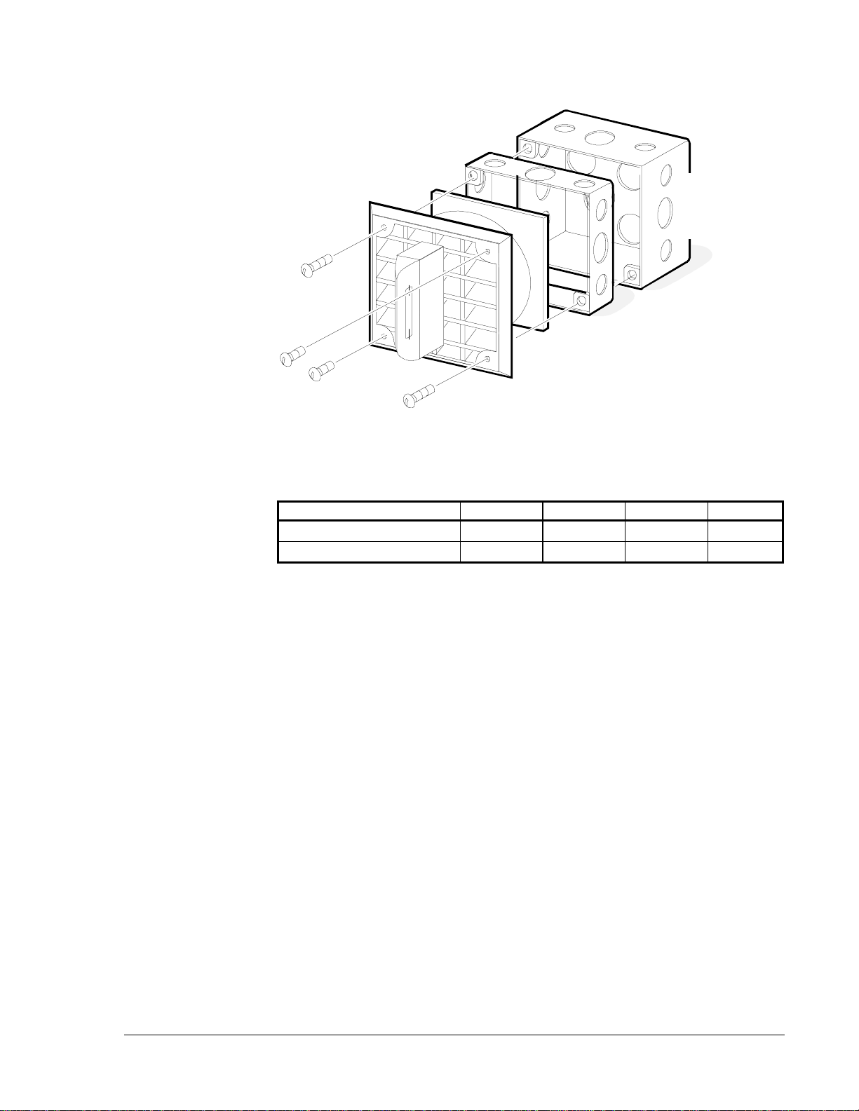
Notification Appliances—ET Series Speakers and Strobe Speakers 13
et_a
DBB-R or Standard
4 inch S
q
uare
x 2-1/8 inch
Deep Backbox
Strobe/ET-1070 Speaker
4 inch S
q
uare x 1-1/2 inch
Extension Rin
g
(
2
)
No. 8-32 Screws
Figure 3: Flush Mounting (Option A)
Table 6: Mounting Option A Conductor Limitations
Extension Ring Depth AWG 18 AWG 16 AWG 14 AWG 12
1-1/2 In. 8884
2-1/8 In. 8888
Mounting Option A

14 Notification Appliances—ET Series Speakers and Strobe Speakers
Figure 4: Flush Mounting (Option B)
Table 7: Mounting Option B Conductor Limitations
Extension Ring Depth AWG 18 AWG 16 AWG 14 AWG 12
1-1/2 Inches 8884
2-1/8 Inches 8888
Mounting Option B
DBB-R or Standard
4 inch S
q
uare
x 2-1/8 inch
Deep Backbox
et_b
4 inch S
q
uare x 1-1/2 inch
Extension Rin
g
(
2
)
No. 8-32 Screws
Strobe/ET-1090 Speaker
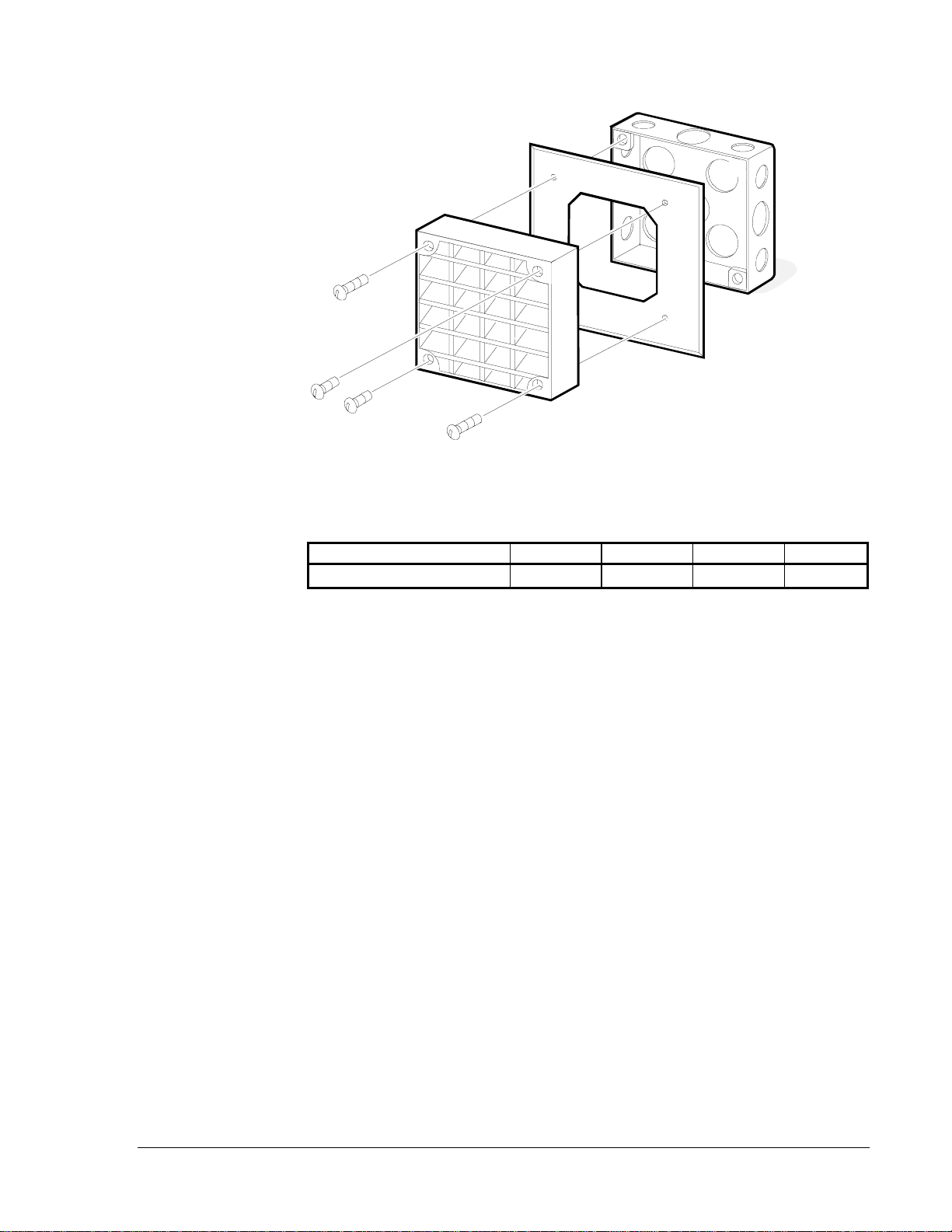
Notification Appliances—ET Series Speakers and Strobe Speakers 15
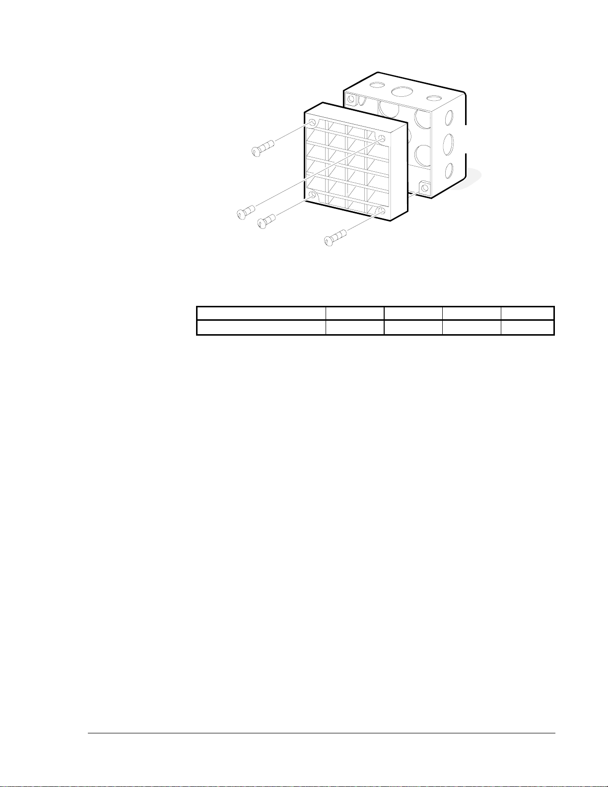
Figure 5: Flush Mounting (Option C)
Table 8: Mounting Option C Conductor Limitations
Extension Ring Depth AWG 18 AWG 16 AWG 14 AWG 12
1-1/2 Inches 8884
2-1/8 Inches 8888
Mounting Option C
DBB-R or Standard
4 inch S
q
uare
x 2-1/8 inch
Deep Backbox
et_c
4 inch S
q
uare x 1-1/2 inch
Extension Rin
g
Strobe/ET-1080 Speaker
(
2
)
No. 8-32 Screws
(
2
)
No. 10-32 Screws
16 Notification Appliances—ET Series Speakers and Strobe Speakers
et_d
Strobe/ET-1070 Speaker
(
2
)
No. 8-32 Screws
SBB-R Surface Backbox
with No. 8-32 and No. 6-32
Screws and Bushin
g
Figure 6: Surface Mounting (Option D)
This backbox is compatible with wiremold and conduit. The mounting holes are suitable
for single gang, double gang, 4 inch square, 3-1/2 or
4 inch octagon, or round boxes. For in-out wiring use a separate conduit entrance and
exit, if necessary, to comply with NEC limits on maximum conductors in conduit.
Table 9: Mounting Option D Conductor Limitations
AWG 18 AWG 16 AWG 14 AWG 12
Maximum Conductors 8888
Mounting Option D
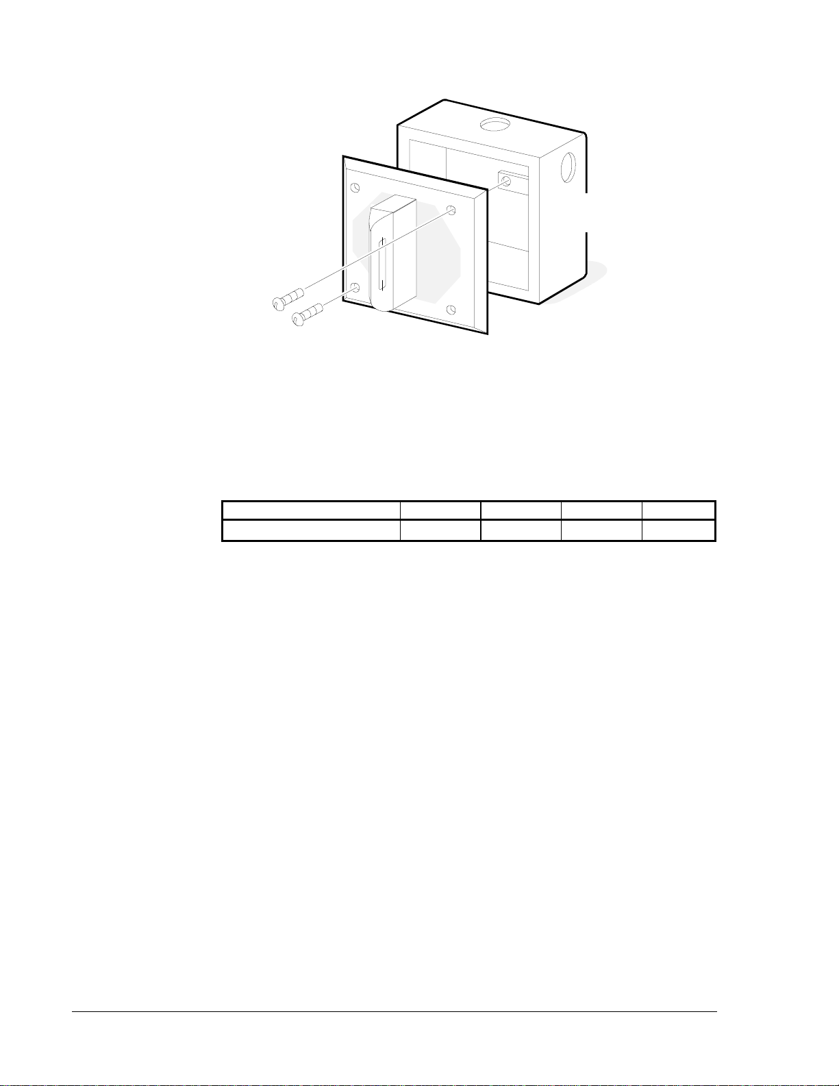
Notification Appliances—ET Series Speakers and Strobe Speakers 17
BB-R or
4 inch S
q
uare
x 1-1/2 inch
Deep Backbox
to be Mounted
in W all
et_e
ET-1010 Speaker
Semi-flush Plate
(
SFP-R
)
(
2
)
No.8-32 Screws
(
2
)
No.10-32 Screws
Figure 7: Semi-Flush Mounting (Option E)
Table 10: Mounting Option E Conductor Limitations
AWG 18 AWG 16 AWG 14 AWG 12
Maximum Conductors 4444
Mounting Option E
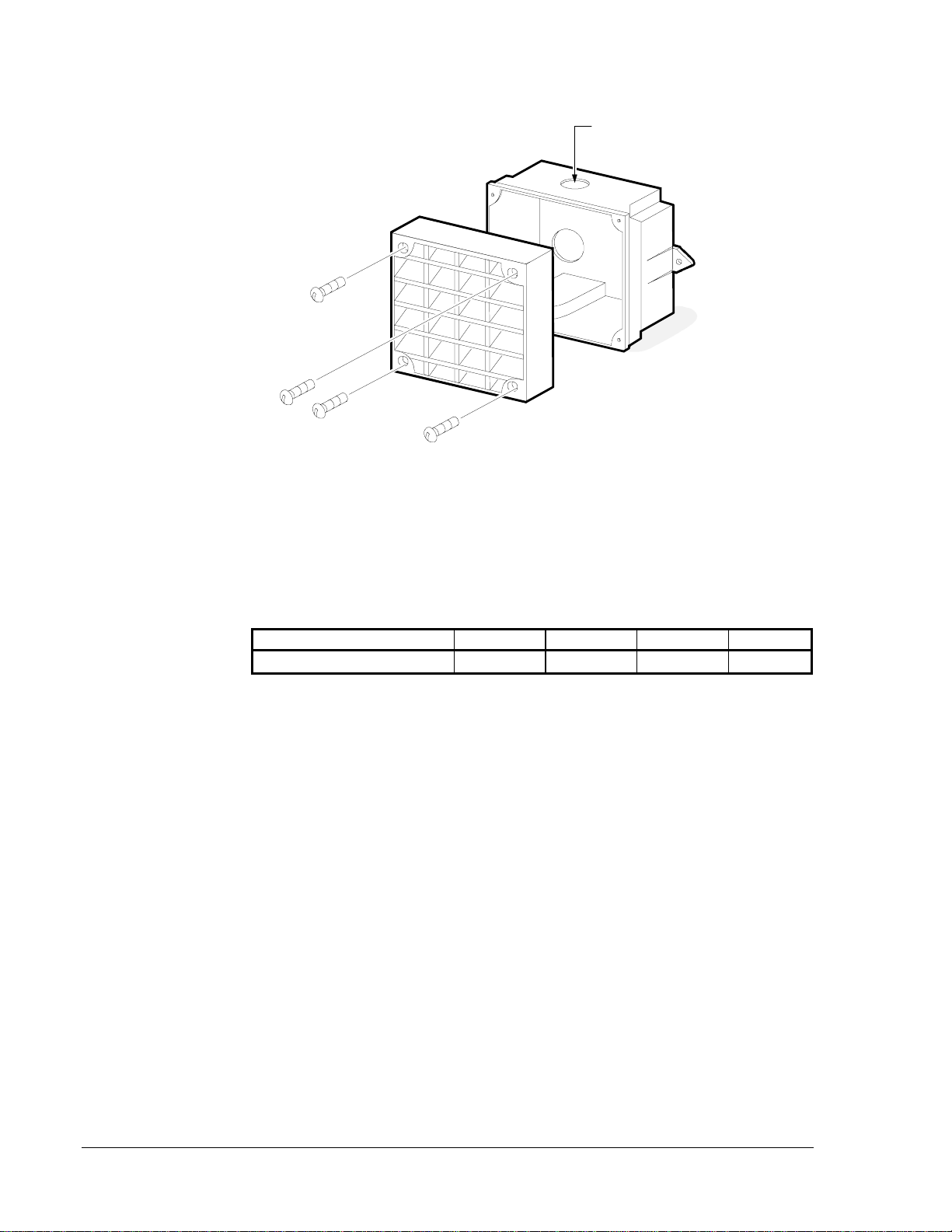
18 Notification Appliances—ET Series Speakers and Strobe Speakers
et_f
ET-1010 Speaker
1/2 inch Conduit
Entrance on Top
WBB-R Weather
Resistant Backbox
to be Mounted
on Wall Surface
(
4
)
No. 8-32 Screws
Figure 8: Weather Resistant Mounting (Option F)
Use mounting Option F for weather resistant installations. The outdoor backbox must be
mounted vertically with top as marked to allow any moisture or condensation to drain
properly through the drain holes on the bottom of the backbox. Use threaded conduit
entrance when using a weather resistant backbox. Do not use the knockout entrance.
Table 11: Mounting Option F Conductor Limitations
AWG 18 AWG 16 AWG 14 AWG 12
Maximum Conductors 4444
Mounting Option F
Notification Appliances—ET Series Speakers and Strobe Speakers 19
et_g
ET-1010 Speaker
DBB-R Deep Backbox
to be Mounted
on W all Surface
(
2
)
No. 8-32 Screws
(
2
)
No. 10-32 Screws
Figure 9: Surface Mounting (Option G)
Table 12: Mounting Option G Conductor Limitations
AWG 18 AWG 16 AWG 14 AWG 12
Maximum Conductors 4444
Mounting Option G

20 Notification Appliances—ET Series Speakers and Strobe Speakers
Figure 10: Concealed Conduit Mounting (Option H)
Table 13: Mounting Option H Conductor Limitations
AWG 18 AWG 16 AWG 14 AWG 12
Maximum Conductors 4444
Mounting Accessories
Table 14 lists the special backboxes and adaptor plates used in the mounting options
illustrated in Figure 3 through Figure 10.
Table 14: Mounting Accessories
Part Number Description
SBB-R 5-1/2 in. x 5-1/2 in. x 3-1/2 in. Surface Backbox
DBB-R 4 in. x 4 in. x 2-1/8 in. Deep Backbox
WBB-R 4-1/8 in. x 4-1/8 in. x 2 in. Weather Resistant Backbox
SFP-R 6 in. x 6 in. x 1/4 in. Semi-flush Plate
AP-R 6 in. x 6 in. x 1/4 in. Adapter Plate
Mounting Option H
et_h
Existin
g
Box
on Wall
AP-R Adaptor Plate with
No. 8-32 and No. 6-32
Screws and Bushin
g
DBB-R Deep Backbox
with No. 8-32 Screws
ET-1010 Speaker
(
2
)
No. 8-32 Screws
(
2
)
No. 10-32 Screws
This manual suits for next models
15
Table of contents


