Metasys AFAWS Series User manual

Fire Management Accessories Manual 445
Miscellaneous Section
Technical Bulletin
Issue Date 0399
© 1999 Johnson Controls, Inc. 1
Code No. LIT-445215 www.johnsoncontrols.com
Preliminary—This information may change.
General Background 3
System Wiring 5
Assembly of Units with Coiled Cord Handsets 7
Assembly of Units with Armored Cable Handsets 9
Emergency Telephone Stations (AFAWS-Series)

Preliminary—This information may change.
2 Miscellaneous—Emergency Telephone Stations (AFAWS-Series)

Preliminary—This information may change.
Miscellaneous—Emergency Stations (AFAWS-Series) 3
General Background
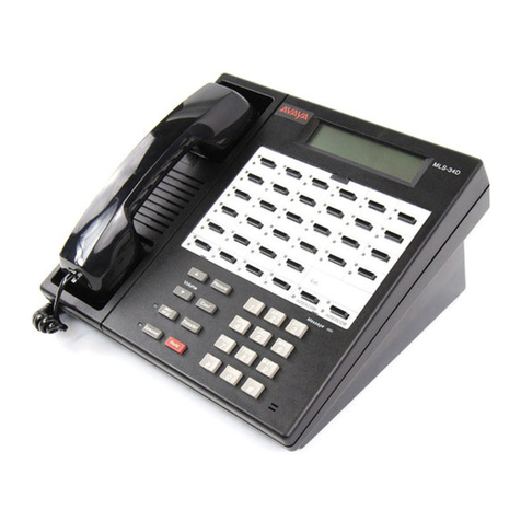
Automatic Fire Alarm Warden Station (AFAWS-Series) telephones are
compatible with the FFT-7 and FFT-7S master telephone stations. The
series has a handset with a push-to-talk switch, a hearing aid-compatible
speaker, and an indicator that illuminates when the warden station is
connected to the master telephone station. Up to seven handsets
(including the master handset) may be operated simultaneously. AFAWS
components are illustrated in Figure 1.

Preliminary—This information may change.
4 Miscellaneous—Emergency Telephone Stations (AFAWS-Series)
Armored
Cable Coiled Cord
(AFAWS-TELC)
(AFAWS-TELA)
Temp ere d
Glass
Hammer
Backbox
(AFAWS-BX) (BRKG-N)
Surface Mounting Flush Mounting
(AFAWS-LS) (AFAWS-LR)
Flush Mounting
Surface Mounting
(AFAWS-KS) (AFAWS-KR)
Firefighter's Telephone
Firefighter's Telephone
Firefighter's Telephone
Firefighter's Telephone
Figure 1: AFAWS Series Components

Preliminary—This information may change.
Miscellaneous—Emergency Stations (AFAWS-Series) 5
System Wiring
Telephone system wiring, from the FFT-7/FFT-7S through the control
point such as the XPM-8 to the warden’s station, must not be connected to
or run in the same conduit or cable tray as Signal Alarm Circuits (SLCs),
speaker circuits, strobe circuits, cable TV, or other noise producing
circuits.

Preliminary—This information may change.
6 Miscellaneous—Emergency Telephone Stations (AFAWS-Series)

Preliminary—This information may change.
Miscellaneous—Emergency Stations (AFAWS-Series) 7
Assembly of Units with Coiled
Cord Handsets
This assembly procedure is for telephones with coiled cord handsets.
After the enclosure is mounted and the system wiring is in place (refer to
Figure 2), complete the following steps:
1. Attach system wiring to the terminal strip on the telephone chassis
assembly. See Figure 2 or 3.
2. Install 6-32 nut in backbox. Do not tighten.
3. Install telephone chassis assembly in backbox.
4. Install trim ring on backbox with 6-32 wing nuts. Do not tighten.
5. Install door assembly.
6. Tighten wing nuts.
Notes: Telephone circuits are supervised and power-limited.
Use twisted pair shielded cable for telephone circuit wiring. For
best operation, terminate shield at FFT-7/S 24V power supply
common (-).
Maximum telephone circuit wire resistance is 40 ohms.
For (End-of-Line Resistor) ELR connection to devices with
terminals, use Resistor 71252. For ELR connection to devices with
flying leads, use Resistor 71245. In Canada, N-ELR Resistor
Assembly is required.
Refer to the fire panel manual for Underwriters Laboratories (UL)
power-limited requirements and further information.

Preliminary—This information may change.
8 Miscellaneous—Emergency Telephone Stations (AFAWS-Series)
1
5
2
6
3
7
4
8
9
To another telephone. At last telephone
use R-47K End-of-Line Resistor, or return
to XPC-8 P2.14 (-) and P2.13 (+) for
Style Z connection.
Red
Blk
OFF HOOK
Blk
Red
ON HOOK
COM
RING OUT
TIP OUT
RING
TIP
AUX SW
Form-C
Dry Contact
(1A 30 V )
RMS
Install R-47K End-of-Line
Resistor at end of Class B
FFT-7/S telephone circuit.
To
AFAWS
Series
Telephones
Ring
Tip
Activated
Polarity
Telephone
Loop IN
SLC
Control Module Wiring
XPC-8
AFAWS Series
Telephone
Activated
Polarity
Shown
Telephonic Loop
In In In InOut Out Out Out
Optional 4-wire Return
(Class A Connection. Omit R-47K Resistor).
Up to six external telephone handsets may be
connected to one FFT-7/S.
Maximum line resistance from FFT-7/S to farthest
telephone must not exceed 40 ohms.
P2
16151413121110987654321
6
Use twisted pair
shielded wiring
and connect shields
to FFT-7/S 24V
power supply
common (-).
P3
532
FFT-7/S
For further information, see the fire panel manuals.
afawcnct
R-47K
Figure 2: Telephone to XPC-8 and Control Modules
Connections

Preliminary—This information may change.
Miscellaneous—Emergency Stations (AFAWS-Series) 9
Assembly of Units with
Armored Cable Handsets
This assembly procedure is for telephones with armored cable handsets.
Complete the following steps when the enclosure has been mounted and
the system wiring is in place (refer to Figure 3).
1. Attach system wiring to the terminal strip on the telephone chassis
assembly. See Figure 2 or 3.
2. Install 6-32 nut in backbox. Do not tighten.
3. Inset armored cable end into slot on top of telephone chassis assembly.
4. Install telephone chassis assembly in backbox.
5. Install trim ring on backbox with 6-32 wing nuts. Do not tighten.
Notes: Telephone circuits are supervised and power-limited.
Use twisted pair shielded cable for telephone circuit wiring. For
best operation, terminate shield at FFT-7/S 24V power supply
common (-).
Maximum telephone circuit wire resistance is 40 ohms.
For ELR connection to devices with terminals, use Resistor 71252.
For ELR connection to devices with flying leads, use
Resistor 71245. In Canada, N-ELR Resistor Assembly is required.
Refer to the fire panel manual for UL power-limited requirements
and further information.

Preliminary—This information may change.
10 Miscellaneous—Emergency Telephone Stations (AFAWS-Series)
B+ A+ A- B- B+ A+ A- B- B+ A+ A- B- B+ A+ A- B-
Afawvcm4
NFPA Style Z
AUX SW
Tip
Ring
Tip out
Ring out
Com
On hook
Off hook
AUX SW
Tip
Ring
Tip out
Ring out
Com
On hook
Off hook
Form-C
Hook-Switch Activated
Dry Contact
(1A 30 V )
RMS
NFPA Style Y
4.7K 0.5W ELR
Part Number 71252
(See Note 4, Below)
Terminate each
unused circuit
with 4.7K 0.5W ELR
Part Number 71245.
Activated
Polarity
Shown
VCM-4
VCM-4
Typical Telephone Circuits
Telephone Power
Polarity (from FFT-7/S)
A
B
C
D
E
F
G
H
SPEAKER
CIRCUITS
SPEAKER
CIRCUITS
AB CD
Figure 3: AFAWS Series Telephone to VCM-4 Circuit
Connections
Notes: Telephone circuits are supervised and power-limited.
Twisted pair shielded cable should be used for telephone circuit
wiring. For best operation, terminate shield at FFT-7/S 24V power
supply common (-).
Maximum telephone circuit wire resistance is 40 ohms.
For ELR connection to devices with terminals, use Resistor 71252.
For ELR connection to devices with flying leads, use
Resistor 71245. In Canada, N-ELR Resistor Assembly is required.
Refer to the fire panel manual for UL power-limited requirements
and further information.

Preliminary—This information may change.
Miscellaneous—Emergency Stations (AFAWS-Series) 11
Notes

Preliminary—This information may change.
12 Miscellaneous—Emergency Telephone Stations (AFAWS-Series)
Notes
Controls Group www.johnsoncontrols.com
507 E. Michigan Street FAN 445
P.O. Box 423 Fire Management Accessories Manual
Milwaukee, WI 53201 Printed in U.S.A.
This manual suits for next models
2
Table of contents
