Metek LAND LWIR User manual

Long Wavelength Infrared Thermal Imaging Camera
i
QUALITY CUSTOMER SOLUTIONS
LWIR THERMAL IMAGER
INSTALLATION GUIDE
PUBLICATION NO814975
LANGUAGE: ENGLISH
ISSUE: 1
DATE: 07 DECEMBER 2021
Health and Safety Information
Read all of the instructions in this booklet - including all the WARNINGS and CAUTIONS
- before using this product. If there is any instruction which you do not understand, DO
NOT USE THE PRODUCT.
Safety Signs
WARNING
Indicates a potentially hazardous situation which, if not avoided, could result in death or
personal injury.
CAUTION
Indicates a potentially hazardous situation which, if not avoided, could result in minor or
moderate injury to the user or users, or result in damage to the product or to property.
NOTE
Indicates a potentially hazardous situation which, if not avoided, could result in damage or loss of data.
Signs and Symbols used on equipment and Documentation
Caution, risk of electric shock.
Caution, attention to possibility of risk of damage to the product, process or surroundings. Refer
to instruction manual.
Caution, hot surface.
Protective Conductor Terminal.
Observe precautions for handling electrostatic discharge sensitive devices.
Equipment Operation
Use of this instrument in a manner not specied by AMETEK Land may be hazardous. Read and
understand the user documentation supplied before installing and operating the equipment.
The safety of any system incorporating this equipment is the responsibility of the assembler.
Protective Clothing, Face and Eye Protection
It is possible that this equipment is to be installed on, or near to, machinery or equipment operating at
high temperatures and high pressures. Suitable protective clothing, along with face and eye protection
must be worn. Refer to the health and safety guidelines for the machinery/equipment before installing
this product. If in doubt, contact AMETEK Land.
Wear Protective Gloves Wear Protective Clothing
Wear Eye Protection Wear Ear Protection
Wear Safety Boots Wear Face Protection
Electrical Power Supply
Before working on the electrical connections, all of the electrical power lines to the equipment must
be isolated. All the electrical cables and signal cables must be connected exactly as indicated in these
operating instructions. If in doubt, contact AMETEK Land.
IMPORTANT INFORMATION - PLEASE READ
Contact Us
UK - Droneld
Land Instruments International
Tel: +44 (0) 1246 417691
USA - Pittsburgh
AMETEK Land, Inc.
Tel: +1 412 826 4444
China
AMETEK Land China Service
Tel: +86 21 5868 5111 ext 122
India
AMETEK Land India Service
Tel: +91 - 80 67823240
Email: [email protected]
Web: www.ametek-land.com
For further details on all AMETEK Land oces, distributors and representatives, please visit our website.
Storage
The instrument should be stored in its packaging, in a dry sheltered area.
The maximum storage temperature is 10 °C (18 °F) higher than the maximum operating temperature.
The minimum storage temperature is 10 °C (18 °F) lower than the minimum operating temperature.
Refer to the Technical Specication for details of the operating temperature limits.
Unpacking
Check all packages for external signs of damage. Check the contents against the packing note.
Lifting Instructions
Where items are too heavy to be lifted manually, use suitably rated lifting equipment. Refer to the
Technical Specication for weights. All lifting should be carried out in accordance with local and national
regulations.
Return of Damaged Goods
IMPORTANT If any item has been damaged in transit, this should be reported to the carrier and to the
supplier immediately. Damage caused in transit is the responsibility of the carrier not the supplier.
DO NOT RETURN a damaged instrument to the sender as the carrier will not then consider a claim. Save
the packing with the damaged article for inspection by the carrier.
Return of Goods for Repair
If you need to return goods for repair please contact our Customer Service Department for details of the
correct returns procedure.
Any item returned to AMETEK Land should be adequately packaged to prevent damage during transit.
You must include a written report of the problem together with your own name and contact information,
address, telephone number, email address etc.
Design and Manufacturing Standards
The Quality Management System of Land Instruments International is approved to BS EN ISO 9001 for
the design, manufacture and on-site servicing of combustion, environmental monitoring and non-contact
temperature measuring instrumentation.
Registered ISO 9001 Management System approvals apply in the USA.
UK Calibration Laboratory: UKAS 0034.
USA Calibration Laboratory: ANAB Accredited ISO/IEC 17025.
National Accreditation Board for Testing and Calibration Laboratories approvals apply in India.
Operation of radio transmitters, telephones or other electrical/electronic devices in close proximity
to the equipment while the enclosure doors of the instrument or its peripherals are open, may cause
interference and possible failure where the radiated emissions exceed the EMC directive.
The protection provided by this product may be invalidated if alterations or additions are made to the
structural, electrical, mechanical, pneumatic, software or rmware components of this system. Such
changes may also invalidate the standard terms of warranty.
Copyright
This manual is provided as an aid to owners of AMETEK Land’s products and contains information
proprietary to AMETEK Land. This manual may not, in whole or part, be copied, or reproduced without the
expressed written consent of AMETEK Land.

Thermal Imaging CameraLWIR
Contents
1 Introduction 1-1
1.1 Points to note on installation 1-1
1.2 Using compressed air for air purging 1-1
2 Specications 2-0
2.1 Nomenclature 2-0
2.2 SpecicationTable 2-1
2.3 LED Status Indicators 2-2
3 Electrical Connections 3-1
3.1 ConnectingthemainsinputtotheTRACOPowerSupplyUnit 3-1
3.2 UsinganalternativePowerSupplyUnit 3-3
4 Installation Diagrams 4-0
5 UsingtheWebServerInterface 5-1
5.1 ConnectingtotheWebServer 5-1
5.2 AbouttheWebServerInterface 5-3
5.3 AbouttheWebServerMenu 5-4
5.4 Settings 5-4
5.5 Frame Settings 5-5
5.6 RegionsofInterest(ROI) 5-6
5.7 WorkingwithRegionsofInterest(ROI) 5-7
5.8 5.8I/O 5-9
5.9 SelectingaColourPalette 5-12
5.10AdjustingtheTemperatureSpan 5-12
5.11TimeFunctionProcessing 5-13
6 Spares&Accessories 6-0
6.1 StandardPowerSupplies 6-0
6.2 PoweroverEthernet(PoE)PowerSupplies 6-0
6.3 PowerI/OCables 6-0
6.4 Communications/PoECables 6-1
6.5 HousingsandAccessories 6-2

1-1
LWIRThermal Imaging Camera
Installation Guide
This guide gives you information on how to install the LWIR thermal
imaging camera and its installation accessories.
Theseinstructionsareprovidedasaseriesofsimpleinstallationdiagrams,
coveringtheinstallationoftheLWIRthermalcameraanditsmountings,
accessories and services.
Theequipmentmustbeused,maintainedandservicedbyproperlytrained
personnel,capableoffollowingtheproceduresgivenintheseinstructions.
Safetymaybeimpairedifthesystemisnotusedasindicated.
Itisimportanttochecktheequipmentwithwhichyouhavebeensuppliedand
thenreadtheseinstructionsthoroughlybeforeproceedingwithinstallation.
1.1 Points to note on installation
• WhenchoosingalocationtoinstalltheLWIRthermalimagingcamera,
ensurethatthecamerahasanunobstructedviewofthetargettobe
measured.
• Trytochooseamountinglocationthatpermitseasyaccesstothe
systemcomponentswhereverpossible,asthiswillspeedupanysystem
maintenance and repair.
• Ensure that the mounting locations chosen for the camera and its
accessoriesareasfreeaspossiblefromvibration,dust,steamandsmoke
etc.
• Ensure that the mounting locations chosen for the camera and its
accessoriesallowforthelengthsofinterconnectingcablesthatyouhave
ordered.Also,ensurethatallcablerunsareassecureandunobtrusiveas
possible.
1.2 Using compressed air for air purging
Ifyourapplicationrequirestheuseoftheairpurgingandyouintendtouse
compressedairtosupplyairtothepurge,thenthefollowingpointsmustbe
noted:
• Ifpossible,connectthecompressedairsupplytothepurgeviaa1m
lengthof35mmdiametersmoothboretube.Thiswillincreasetheairow
rateslightly.
• Theminimumrecommendedairpressureis20psi(1.4bar).
• Theminimumrecommendedowrateis350l/min.
• Occasionalcleaningwillberequiredtopreventthebuildupofeveryday
dirtonsitewhenthepurgeiso.
INTRODUCTION
1
Thermal Imaging CameraLWIR
2.1 Nomenclature
Thethermalimagerdetaillabelisontherearfaceofthethermometerabove
theLANDlogolabel.
MakeanoteofyourthermometersinstrumentType and Serial Number in the
spaceprovidedbelow.
Type:
SerialNumber:
Intheexampleinthetablebelow,weexaminethenomenclatureforathermal
imagerwithaninstrumenttypelabelwhichreads:
TYPE: LWIR 640 0/500C 50 LF
Example Description Options Meaning
LWIR Series Name LWIR Longwavelengthinfrared
640 PixelResolution 640 640 x 480 pixels
0/500C TemperatureRange 0/500C 0 to 500 °C
100/1000C 100 to 1000 °C
50 HorizontalFieldofView 25 25 °
50 50 °
LF FrameRate HF 60 fps
LF 7.5 fps
Fromthetableabove,itcanbeseenthatthecamerainourexamplehasthefollowing
specication:
• Longwavelengthinfraredthermalimager
• 640 x 480 pixel resolution
• 0 to 500 °C temperature range
• 50°horizontaleldofview
• 7.5 frames per second frame rate
RefertothistablewhencheckingyourinstrumentTypelabeldetails.
SPECIFICATIONS
2
Installation Guide2-0
2-1
LWIRThermal Imaging Camera
Installation Guide
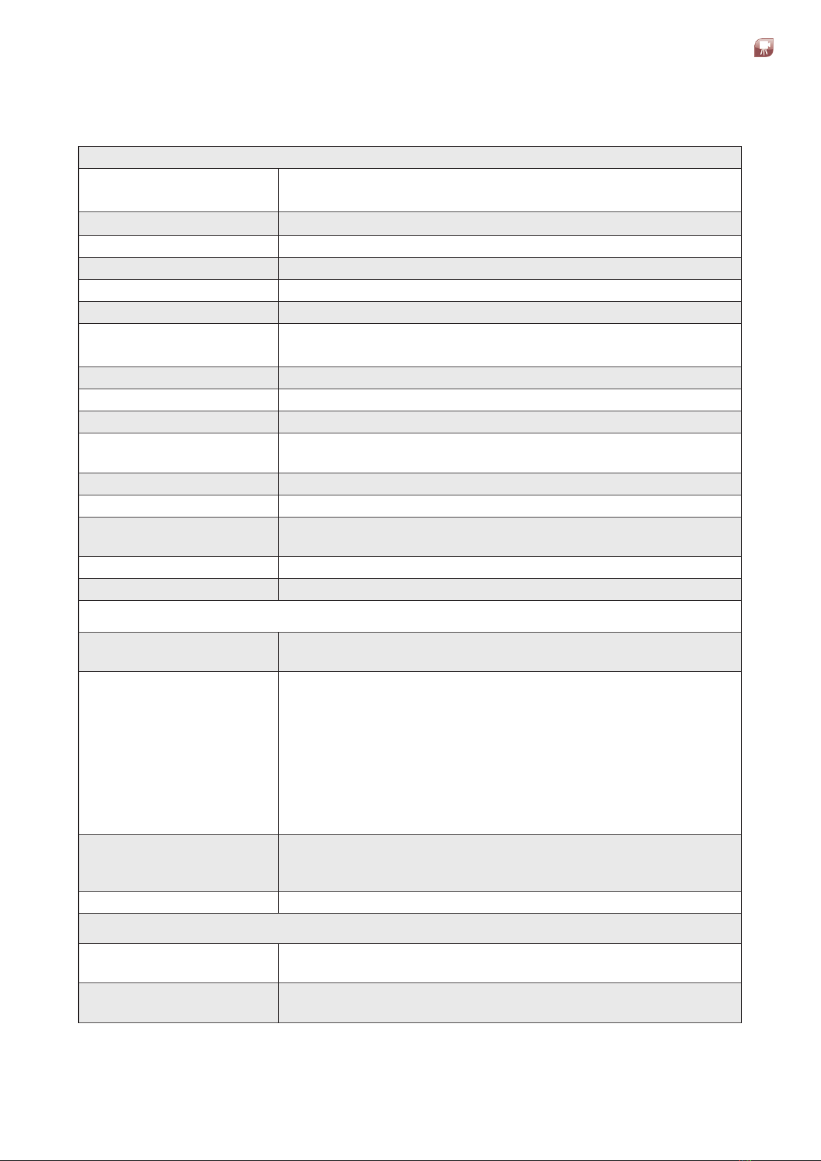
2.2 Specification Table
Camera Unit
MeasurementRange: 0to500°C/32to932°F
100 to 1000 °C / 212 to 1832 °F
PixelResolution: 640 x 480
Pixel Size/ Pitch 17μm
SpectralResponse: 8to14μm
MaxFrameRate:* 60 fps / 7.5 fps
Detector: 640x480AmorphousSilicon
Optic(HFOVxVFOV): 50 ° x 37 °
25 ° x 17 °
FocusRange: Min0.3mtoinnity(motorisedfocus)
Accuracy: 2 °C or 1 .5 % °C of reading
NETD: 40mk(@20°C)(-20to120°C)7.5Hz
Dimensions: 80x80x222mm(max)/3.14x3.14x8.7in
(includinglens)
PowerRating: 12to24VDC,+/-10%12W/IEEE802.3atPoE+
Weight: 1.6kg/3.5lb
AmbientTemperature: -20to60°C(-4to140°F)
0to95%humidity(non-condensing)
EnvironmentalRating: IP65/NEMA4
Compliance EMC(EN61326-1)
Camera Supply and I/O
Digital Connections: M12Xcoded8-wayconnector:10/100/1000Ethernet&IEEE
802.3atPoE+
AnalogConnections: 8-pinBinderConnector:2pins-12-24VDCPowerInput
6pinFunctionscanbeassignedtointernalimageprocessing
algorithms
1x4to20mAoutput
1x4to20mAoutputORrelayoutput
1x4to20mAinputORDigitalInputORrelayoutput
CameraWebBrowserforalignment&internalimage
processinganalogI/Osetup
Signal-LED: Visibleonrearofcameraonly(notwithjacket)3xLED
-Power/Status,EthernetComms&Camerainternal
temperature
Service: Water,instrumentairforoptionalcoolingenclosures
SMART Functionalities
IntegratedWebServer: RemoteaccessviaGbitEthernetinterface
IntegratedWebServerprovideslivethermalimage
AutonomousOperation: 3ROIsandcongurationofintegratedI/Osforfull
autonomous operation
Continued...
Thermal Imaging Camera
Installation Guide
LWIR
2-2
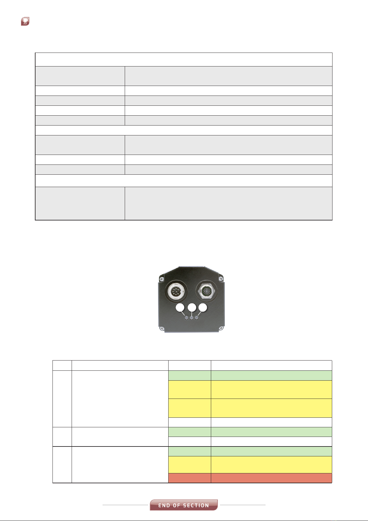
2.3 LED Status Indicators
TheLEDsontherearfaceoftheLWIRThermalImagingCamera(Fig2-11)are
used to indicate the status of the camera operation.
1 2 3
Fig.2-1LWIRThermalImagingCamerastatusLEDs
ThetablebelowgivesanexplanationoftheLEDs.
LED Function Colour Meaning
1Power/Firmwarestatus
Green PowerON
Yellow
(Flashing)
Warning.Readingsmaybe
intermittent
Yellow
(Solid)
Alarm.Cameraunabletofunction
correctly
OFF NoPower
2Ethernet Client Connection
statuse.g.IMAGEPro
Green Connected to Client
O NOClientConnected
3CameraTemperatureStatus
Green CameraTemperatureOK
Yellow
(Flashing)
CameraTemperatureWarning
Red CameraTemperatureAlarm
Thermal Imaging PSU Module (UL Approved)
Components &
Connections:
Powersupply,GbEthernetcommunications(switch)/PoE+
Fibreopticdataconnection(option)
EnvironmentalRating: IP65/NEMA4
Size: 380 x 380 x 211mm / 15 x 15 x 8.3 in
Weight: 15kg(33.1lbs)
ULApproval: ListedtoUL508A&CSA-C22.2No.FileNumberE499440
Image Processing
Software: IMAGEProandIMAGEViewer
IMAGEProApplication(e.gAssetMonitor)
Workstation: PC-Workstation(option)
Interfacing: OpenDataInterface,ModbusTCP,MoxaI/Ounit
Standard Accessories
Accessories(optional): ThermalImagingPSUModule(ULApproved),ProcessImager
PowerSupply,LWIR/MWIRIndustrialHousingAssemblyand
Purge,LightHousingwithPurge,cables,brackets,Blower
System,SoftwareandWorkstation

3-1
LWIRThermal Imaging Camera
Installation Guide
ELECTRICAL
CONNECTIONS
3
The basic system electrical connections are as follows:
• MainsinputtotheTRACOPowerSupplyUnit*
• 24VoutputfromTRACOPowerSupplyUnit*totheLWIRcamera
• EthernetcablefromLWIRCameratotheProcessImagingWorkstation
*TheLWIRCameracanbepoweredbyanalternativepowersupply,viacable
PartNº806032orPartNº806033(Seesection3.2).
3.1 Connecting the mains input to the TRACO Power Supply Unit
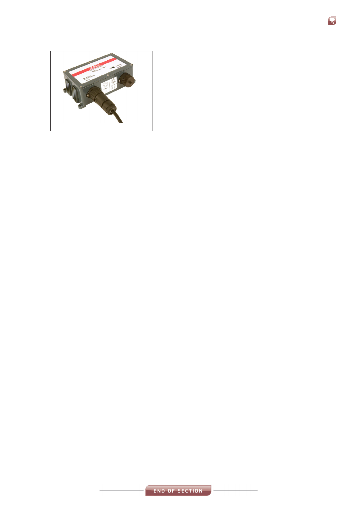
TheTRACOPowerSupplyUnitissuppliedwith
a3-pinACinputconnector(Fig.3-1).Youwill
needtodisassemblethisconnectortoinstall
thecable.
1) UnscrewthecoverfromthemainsInput
onthePowerSupplyUnit.
Fig. 3-1
Fig. 3-2
2) Theeasiestwaytodisassemblethe3-pin
ACinputconnectoristorstscrewthe
connectorassemblyontotheinputsocket
(Fig.3-2).

Thermal Imaging Camera
Installation Guide
LWIR
3-2
Fig. 3-3
3) Griptherearsectionoftheinputconnector
andunscrewitfromthePowerSupplyUnit
(Fig.3-3).
Fig. 3-4
Fig. 3-6
Theconnectionterminalsinsidetheinput
connectorwillnowberevealed(Fig.3-4).
4) Unscrewtheconnectorfrontsectionfrom
thePowerSupplyUnitanddisassemble
the remaining parts of the connector.
5) Slidetherearlockingring,gasketand
shellbodyoverthemainsinputcable.
6) Stripbackthemainscablewirestothe
appropriate lengths and connect them to
the Inputconnectorterminals(Fig.3-5)
asperthewiringschedulebelow:
Pin 1 = Live
Pin 2 = Neutral
Pin 3 = N/C
E = Earth
7) Themainsinputcableconnectorisnow
readyforre-assemblyandconnectionto
thePowerSupplyUnit(Fig.3-6).Re-
assemblethemainsinputconnector.
Fig. 3-5
3-3
LWIRThermal Imaging Camera
Installation Guide
Fig. 3-7
8) AttachthemainscabletotheInput
connectorofthePowerSupplyUnit
(Fig.3-7).
YoucannowconnecttheTRACOPowerSupply
UnittotheLWIRcameraviaInterfacePCB(Part
Nº807941).
RefertotheInstallationDiagramsinSection4.

Thermal Imaging CameraLWIR
INSTALLATION
DIAGRAMS
4
Installation Guide4-0
This section of the Installation Guide provides a series of simple
installation diagrams, covering the installation of the LWIR thermal
camera and its mountings, accessories and services.

1
1
2
2
3
3
4
4
5
5
6
6
7
7
8
8
A A
B B
C C
D D
E E
F F
THIS DRAWING MUST NOT BE COPIED OR USED OTHER THAN FOR THE PURPOSE OR WHICH IT
WAS ISSUED WITHOUT THE WRITTEN PERMISSION OF:-
DRG. TITLE
MATERIAL
FINISH
Created by
Approved by
DATE
DRG.No.
SURFACE FINISH ALL SHARP CORNERS REMOVED
Technical reference
SCALE
LAND INSTRUMENTS INTERNATIONAL LTD, DRONFIELD, S18 1DJ
C
SHEET
ORIGINALLY USED ON PRODUCT TYPE
Revision
S.Lonsdale
740.123 1
25/08/2021
Installation Drawings for LMIR-MWIR 640 Imager System
0310 LWIR 640 Camera\Accessories
c L
2021
Design Engineering
PROJECTION
DRG.Size
Standard Assembly
DOCUMENT TYPE
A2
Not to Scale
1 of 17
All Materials and Finishes to be RoHS Compliant to Directive 2011/65/EU & (EU) 2015 / 863
Chemicals in breach of EU REACH or US TSCA limits in this product must be reported to Land Instruments
CONFORMS TO BS 8888
TOLERANCING ISO 8015
ISO 2768 -
RESPONSIBLE DEPT
D.Bramhall
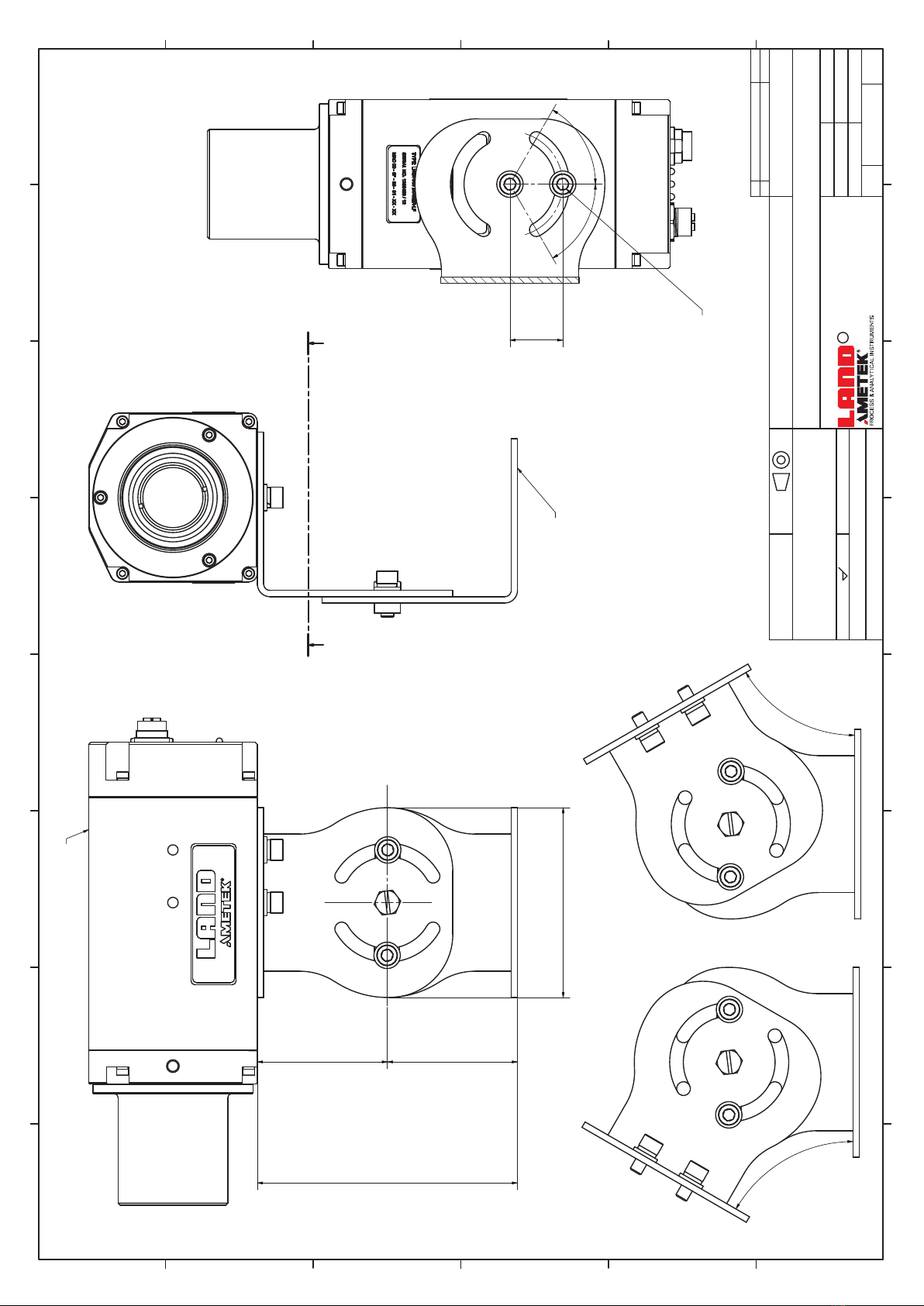
80 [3,1]
80[3,1]
36 [1,4]
50[2,0]
18[0,7]
40[1,6]
162 [6,4]
173 [6,8]
Varies with Lens Type Overall Length
78 [3,1] 25 [1,0]9 [0,3]
9 [0,3] 78 [3,1] 25 [1,0]
1/4-20 UNC - 2B
6mm deep
1/4-20 UNC - 2B
Both Sides
0
REV DESCRIPTION DATE
LWIR/MWIR 640 Imager
M12 8 Way X-Coded PoE Ethernet Connector
M16 8 Way Connector
Power and I/O
See User Guide
for LED Functions
Approximate Overall Camera Lengths
Lens Overall Length
6 Degree 195mm [7.7"]
11 Degree 201mm [8.3"]
25 Degree 201mm [8.3"]
50 Degree 231mm [9.1"]
2 off M6x1 Tapped Holes
6mm deep
2 off M6x1 Tapped Holes
Both Sides
A-A ( 1 : 1 )
A A
1
1
2
2
3
3
4
4
5
5
6
6
7
7
8
8
A A
B B
C C
D D
E E
F F
THIS DRAWING MUST NOT BE COPIED OR USED OTHER THAN FOR THE PURPOSE OR WHICH IT
WAS ISSUED WITHOUT THE WRITTEN PERMISSION OF:-
DRG. TITLE
MATERIAL
FINISH
Created by
Approved by
DATE
DRG.No.
SURFACE FINISH ALL SHARP CORNERS REMOVED
Technical reference
SCALE
LAND INSTRUMENTS INTERNATIONAL LTD, DRONFIELD, S18 1DJ
C
SHEET
ORIGINALLY USED ON PRODUCT TYPE
Revision
S.Lonsdale
740.123 1
25/08/2021
Installation Drawings for LMIR-MWIR 640 Imager System
0310 LWIR 640 Camera\Accessories
c L
2021
Desiign Engineering
PROJECTION
DRG.Size
Standard Assembly
DOCUMENT TYPE
A2
Not to Scale
2 of 17
All Materials and Finishes to be RoHS Compliant to Directive 2011/65/EU & (EU) 2015 / 863
Chemicals in breach of EU REACH or US TSCA limits in this product must be reported to Land Instruments
CONFORMS TO BS 8888
TOLERANCING ISO 8015
ISO 2768 -
RESPONSIBLE DEPT
D.Bramhall
123[4,9]
90 [3,5]
62[2,4]62[2,4]
60°
60°
60°
60°
0
REV DESCRIPTION DATE
LWIR-MWIR Imager
806761 Pan and Tilt Bracket
25[1,0]
2off M6 Cap Head Screws

1
1
2
2
3
3
4
4
5
5
6
6
7
7
8
8
A A
B B
C C
D D
E E
F F
THIS DRAWING MUST NOT BE COPIED OR USED OTHER THAN FOR THE PURPOSE OR WHICH IT
WAS ISSUED WITHOUT THE WRITTEN PERMISSION OF:-
DRG. TITLE
MATERIAL
FINISH
Created by
Approved by
DATE
DRG.No.
SURFACE FINISH ALL SHARP CORNERS REMOVED
Technical reference
SCALE
LAND INSTRUMENTS INTERNATIONAL LTD, DRONFIELD, S18 1DJ
C
SHEET
ORIGINALLY USED ON PRODUCT TYPE
Revision
S.Lonsdale
815130 1
11/10/2021
Installation Drawings for LMIR-MWIR 640 Imager System
0310 LWIR 640 Camera\Accessories
c L
2021
Design Engineering
PROJECTION
DRG.Size
Standard Assembly
DOCUMENT TYPE
A2
Not to Scale
3 of 17
All Materials and Finishes to be RoHS Compliant to Directive 2011/65/EU & (EU) 2015 / 863
Chemicals in breach of EU REACH or US TSCA limits in this product must be reported to Land Instruments
CONFORMS TO BS 8888
TOLERANCING ISO 8015
ISO 2768 -
RESPONSIBLE DEPT
D.Bramhall
71 [2,8] 155 [6,1]
441 [17,4]
168[6,6]
170 [6,7]
89[3,5]
38 [1,5]Ø
106[4,2]
149 [5,8]
140[5,5]
90 [3,5]
M12 8 Way X-Coded
Ethernet PoE Connector
M16 Cable Gland Entry
Customer Power and I/O
or Power Only (Ø5 - 8 Cable)
M16 Cable Gland Entry
Customer I/O Only (Ø5 - 8 Cable)
2 off M6x1 Tapped Holes
175[6,9]
495 [19,5]
Air Inlet for Purge
90[3,5]
186[7,3]
Leave enough space
below to allow for
air purge feed pipe
This Enclosure Is NOT Cooled
65 [2,6]
Required Air Supply Conditions:
•Air supply must be clean filtered and regulated instrument air.
•MIN Flow Rate= 350 l/m for use in applications up to 1000°C
•MIN Pressure = 1.4 bar for use in applications up to 1000°C
•MAX Outlet Air temperature = 40°C
Operating temperature with
heater:
From -20°C up to +60°C.
See Videotec HEG Aluminium Camera
Housing
Manual for further details
1
1
2
2
3
3
4
4
5
5
6
6
7
7
8
8
A A
B B
C C
D D
E E
F F
THIS DRAWING MUST NOT BE COPIED OR USED OTHER THAN FOR THE PURPOSE OR WHICH IT
WAS ISSUED WITHOUT THE WRITTEN PERMISSION OF:-
DRG. TITLE
MATERIAL
FINISH
Created by
Approved by
DATE
DRG.No.
SURFACE FINISH ALL SHARP CORNERS REMOVED
Technical reference
SCALE
LAND INSTRUMENTS INTERNATIONAL LTD, DRONFIELD, S18 1DJ
C
SHEET
ORIGINALLY USED ON PRODUCT TYPE
Revision
S.Lonsdale
815130 1
11/10/2021
Installation Drawings for LMIR-MWIR 640 Imager System
0310 LWIR 640 Camera\Accessories
c L
2021
Design Engineering
PROJECTION
DRG.Size
Standard Assembly
DOCUMENT TYPE
A2
Not to Scale
4 of 17
All Materials and Finishes to be RoHS Compliant to Directive 2011/65/EU & (EU) 2015 / 863
Chemicals in breach of EU REACH or US TSCA limits in this product must be reported to Land Instruments
CONFORMS TO BS 8888
TOLERANCING ISO 8015
ISO 2768 -
RESPONSIBLE DEPT
D.Bramhall
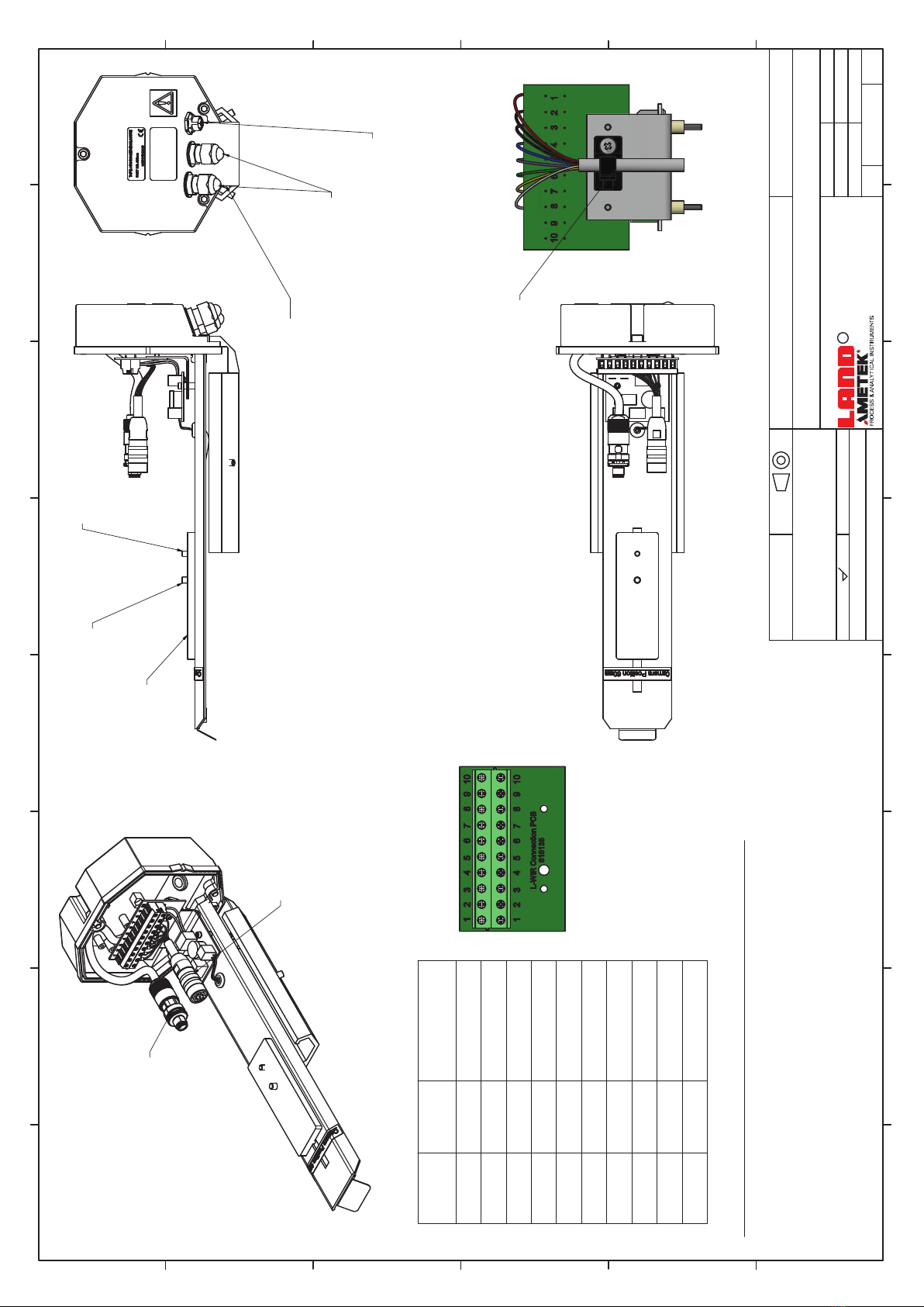
Position front face of camera Lens in to the flange on the purge.
Ensure the lens is located onto the recess face.
Fasten securely in place.
Assembly Instructions for Mounting Camera to Housing.
1,Locate the M5 countersink screw to Camera Centre Height Plate
2, Locate mounting plate into slot on mounting.
3, Fit Camera to mounting plate locating the M5 screw into the rear M6 hole.
4, Fasten Camera in position using the M6 Disc spring washer and M6 cap screw.
Ensure the washer is fitted the correct way.
Connect 2 off cable assemblies
power and Ethernet into rear
of camera.
Camera Centre
Height Plate
M12 8 Way Ethernet Cable
M16 8 Way Mains and I/O Cable Gland Entry for the Power-I/O Cable
or Power Only Cable
(High Temp 815071 25m & 815072 50m)
(STD 815155 20m & 815156 50m) Customer
Wiring
Land Supplied
M12 Ethernet X-Coded Cable Assembly
Customer Connections
Terminal Conections
Power and I/O Wire
LWIR PCB
Terminal No. Wire Colour Function
1Red +24V
2 Black 0V
3Brown +mA Out 1
4 Blue -mA Out 1
5Purple +mA Out 2/Relay 1
6 Green -mA Out 2/Relay 1
7 Yellow + Main/Digin+/Relay 2
8White - Main/Digin+/Relay 2
9N/A +24V
10 N/A 0V
Cable Clamp for Ø6 Cable
M5 Countersink Screw
M6 Cap Screw
D-D ( 1 : 2 )
E ( 1 : 2 )
D D
1
1
2
2
3
3
4
4
5
5
6
6
7
7
8
8
A A
B B
C C
D D
E E
F F
THIS DRAWING MUST NOT BE COPIED OR USED OTHER THAN FOR THE PURPOSE OR WHICH IT
WAS ISSUED WITHOUT THE WRITTEN PERMISSION OF:-
DRG. TITLE
MATERIAL
FINISH
Created by
Approved by
DATE
DRG.No.
SURFACE FINISH ALL SHARP CORNERS REMOVED
Technical reference
SCALE
LAND INSTRUMENTS INTERNATIONAL LTD, DRONFIELD, S18 1DJ
C
SHEET
ORIGINALLY USED ON PRODUCT TYPE
Revision
S.Lonsdale
815130 1
11/10/2021
Installation Drawings for LMIR-MWIR 640 Imager System
0310 LWIR 640 Camera\Accessories
1.6
c L
2021
Design Engineering
PROJECTION
DRG.Size
Standard Assembly
DOCUMENT TYPE
A2
Not to Scale
5 of 17
All Materials and Finishes to be RoHS Compliant to Directive 2011/65/EU & (EU) 2015 / 863
Chemicals in breach of EU REACH or US TSCA limits in this product must be reported to Land Instruments
CONFORMS TO BS 8888
TOLERANCING ISO 8015
ISO 2768 -
RESPONSIBLE DEPT
D.Bramhall
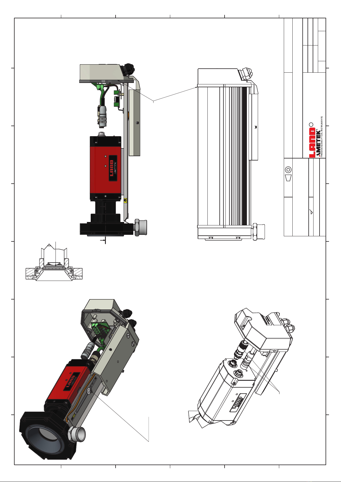
Ensure end face of lens is located up to the
the bottom of the recess in the flange
1. Fit the Camera on to the support plate.
Position the camera forward of the camera position label
and lightly clamp in place so the camera
and can plate move up and down the slot.
Slide the assembled unit in to the main housing.
Carefully locate the lens into the flange on the back of the purge
Push the assembly in to the housing so the
rear gasket is fully engaged with the Housing.
Remove the assembly with camera carefully such that
the position of the position of the camera is not disturbed.
Tighten the screw to firmly secure the camera.
Connect connectors in to
the rear of the camera

1
1
2
2
3
3
4
4
5
5
6
6
7
7
8
8
A A
B B
C C
D D
E E
F F
THIS DRAWING MUST NOT BE COPIED OR USED OTHER THAN FOR THE PURPOSE OR WHICH IT
WAS ISSUED WITHOUT THE WRITTEN PERMISSION OF:-
DRG. TITLE
MATERIAL
FINISH
Created by
Approved by
DATE
DRG.No.
SURFACE FINISH ALL SHARP CORNERS REMOVED
Technical reference
SCALE
LAND INSTRUMENTS INTERNATIONAL LTD, DRONFIELD, S18 1DJ
C
SHEET
ORIGINALLY USED ON PRODUCT TYPE
Revision
S.Lonsdale
815120 1
08/10/2021
Installation Drawings for LMIR-MWIR 640 Imager System
0310 LWIR 640 Camera\Accessories
c L
2021
Design Engineering
PROJECTION
DRG.Size
Standard Assembly
DOCUMENT TYPE
A2
Not to Scale
6 of 17
All Materials and Finishes to be RoHS Compliant to Directive 2011/65/EU & (EU) 2015 / 863
Chemicals in breach of EU REACH or US TSCA limits in this product must be reported to Land Instruments
CONFORMS TO BS 8888
TOLERANCING ISO 8015
ISO 2768 -
RESPONSIBLE DEPT
D.Bramhall
70[2,8]
101 [4,0] 265 [10,4]
124[4,9]
393 [15,5]
M6x1 - 6H
Ø9,5 [3/8"] Ø9,5 [3/8"]
99 [3,9]
145[5,7]28[1,1]
124 [4,9]
Required Water Supply Conditions:
•Water supply must be clean filtered water with a pH level between 6.5 and 8.5
•Rate of Water Hardness = <150mg/l Calcium Carbonate
•Water cooled: Flow < 1 l/min / 13Gal/hr)
•Air cooled: Flow < 450l/min / 16cfm
•Maximum working pressure: 700kN/m²/ 7 Bar (100psi)
•Plain pipe connections 3/8in /9.5mm dia.
•MAX Inlet Water temperature = 40°C
Required Air Supply Conditions:
•Air supply must be clean filtered and regulated instrument air.
•MIN Flow Rate= 350 l/m for use in applications up to 1000°C
•MIN Pressure = 1.4 bar for use in applications up to 1000°C
•MAX Outlet Air temperature = 40°C
38 [1,5]Ø
Air Inlet for Purge Leave Enough Space
BelowTo Allow For
Air Purge Feed Pipe
Water Cooling IN/OUT
2 off M32 Cable Glands
228[9,0]
55[2,2]

B-B ( 0.75 )
B B
1
1
2
2
3
3
4
4
5
5
6
6
7
7
8
8
A A
B B
C C
D D
E E
F F
THIS DRAWING MUST NOT BE COPIED OR USED OTHER THAN FOR THE PURPOSE OR WHICH IT
WAS ISSUED WITHOUT THE WRITTEN PERMISSION OF:-
DRG. TITLE
MATERIAL
FINISH
Created by
Approved by
DATE
DRG.No.
SURFACE FINISH ALL SHARP CORNERS REMOVED
Technical reference
SCALE
LAND INSTRUMENTS INTERNATIONAL LTD, DRONFIELD, S18 1DJ
C
SHEET
ORIGINALLY USED ON PRODUCT TYPE
Revision
S.Lonsdale
815120 1
08/10/2021
Installation Drawings for LMIR-MWIR 640 Imager System
0310 LWIR 640 Camera\Accessories
c L
2021
Design Engineering
PROJECTION
DRG.Size
Standard Assembly
DOCUMENT TYPE
A2
Not to Scale
7 of 17
All Materials and Finishes to be RoHS Compliant to Directive 2011/65/EU & (EU) 2015 / 863
Chemicals in breach of EU REACH or US TSCA limits in this product must be reported to Land Instruments
CONFORMS TO BS 8888
TOLERANCING ISO 8015
ISO 2768 -
RESPONSIBLE DEPT
D.Bramhall
Camera Bracket Assembly
2 off M6 Cap head with spring washer
and plain washer locks camera to chassis
Ensure end face of camera lens locates up to the
lip in the holder
M4 Cap Head, Plain Washer
and Spring Washer
1. Slide camera and bracket assembly in to the housing,
carefully locate the snout of the bracket in to the end of the housing.
2. Secure the bracket in to place using the 2 off M4 screws and washers
Lens
Lens Support
1
1
2
2
3
3
4
4
5
5
6
6
7
7
8
8
A A
B B
C C
D D
E E
F F
THIS DRAWING MUST NOT BE COPIED OR USED OTHER THAN FOR THE PURPOSE OR WHICH IT
WAS ISSUED WITHOUT THE WRITTEN PERMISSION OF:-
DRG. TITLE
MATERIAL
FINISH
Created by
Approved by
DATE
DRG.No.
SURFACE FINISH ALL SHARP CORNERS REMOVED
Technical reference
SCALE
LAND INSTRUMENTS INTERNATIONAL LTD, DRONFIELD, S18 1DJ
C
SHEET
ORIGINALLY USED ON PRODUCT TYPE
Revision
S.Lonsdale
815120 1
08/10/2021
Installation Drawings for LMIR-MWIR 640 Imager System
0310 LWIR 640 Camera\Accessories
c L
2021
Design Engineering
PROJECTION
DRG.Size
Standard Assembly
DOCUMENT TYPE
A2
Not to Scale
8 of 17
All Materials and Finishes to be RoHS Compliant to Directive 2011/65/EU & (EU) 2015 / 863
Chemicals in breach of EU REACH or US TSCA limits in this product must be reported to Land Instruments
CONFORMS TO BS 8888
TOLERANCING ISO 8015
ISO 2768 -
RESPONSIBLE DEPT
D.Bramhall
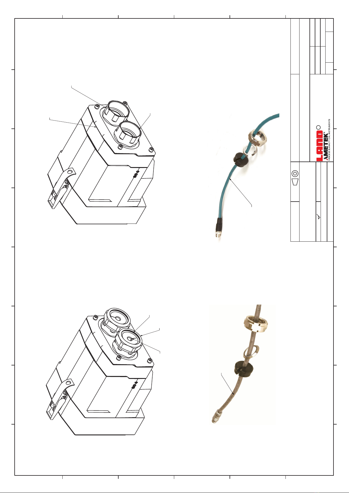
1. Remove the Gland Nut,
Sealing Washer and Cable Seal.
M12 Ethernet Cable Entry
M16 Power and I/O Cable Entry
Assembly of the Cables into the Backcap
Split Cable Seal
Seal Washer
Gland Nut
2. Slide the Gand Nut and Seal Washer over the cable connector
and place the Cable Seal around the Cable approximately 100mm from the connector. (See below)
3. Pass the connector through the gland, press the cable seal into the gland and loosely fasten the nut.
This will allow the cable to reposition when attached to the camera.
Images are for reference ONLY.
Cable types may change
Ethernet Cable
Power and I/O Cable
Table of contents


