METER AROYA RST-W2-P-110-SMA-H User manual

AROYA

i
TABLE OF CONTENTS
1. Introduction..............................................................................................1
2. Operation...................................................................................................3
2.1 Installation ................................................................................................3
3. System.........................................................................................................7
3.1 Specifications............................................................................................7
3.2 Components ............................................................................................12
3.2.1 Gateway (H210)..............................................................................12
3.2.2 Router (H110) and Router Climate (H111) ......................................14
3.2.3 Sensor Station (H310) and Sensor Nose (H311) .............................16
4. Service.......................................................................................................20
4.1 Maintenance............................................................................................ 20
4.2 Repairs ....................................................................................................20
4.3 Troubleshooting....................................................................................... 21
4.4 Customer Support....................................................................................21
4.5 Terms and Conditions ..............................................................................22
AppendixA. Compliance Certifications....................................... 23
A.1 USA.......................................................................................................... 23
A.2 Canada .................................................................................................... 25
18362-00
2.24.2020
Router (H110)
Gateway
(H210) Sensor Nose (H311)
Sensor Nose (H311)
Sensor Nose (H311)
Sensor Nose (H311)
Sensor Nose (H311)
Data to
Cloud
Data transmitted
from Router
to Gateway
Data transmitted
from Sensor
Nose to Router
Data
transmitted
from Sensor
Station to
Router Climate
Data transmitted
from Climate Router
Data transmitted
from Sensor
Station to Gateway
Data transmitted
from Sensor
to Gateway
Sensor Station (H310)
Sensor Station (H310)
Sensor Station (H310)
Sensor Station (H310)
Router Climate
(H111)

1
1. INTRODUCTION
Thank you for choosing the AROYA system from METER Group, Inc. USA. Prior to use, verify
the sensor arrived in good condition.
The AROYA Gateway (H210—Figure5 and Figure6) is powered over a Power Over Ethernet
(POE) enabled device that is compliant with IEEE 802.3af Power Over Ethernet standards.
The H210 Gateway sends and receives data transmitted by the router or sensor stations
and provides the system with an active connection to the cloud server where all data is
processed and presented to the user.
The AROYA Router (H110—Figure7) and AROYA Router Climate (H111—Figure8) are both
powered over a POE enabled device and function as range extenders. The Router/Router
Climate receives data from the Sensor Station/Sensor Nose and transmits data to the
Gateway over ethernet. In addition to being a range extender, the Router Climate can also
support SDI-12 sensor communication to capture microclimate sensor data (Section3.2.2).
An ATMOS14 temperature and relative humidity (RH) sensor and radiation shield are
attached to the H110 Router. The data collected by the sensor is also transmitted to the
Gateway over Ethernet and uses POE.
The AROYA Sensor Station (H310—Figure8 and Figure9) and AROYA Sensor Nose
(H311—Figure10 and Figure11) both contain a TEROS12 soil moisture sensor, location
for plant measuring plant soil moisture, communications components, and an antenna to
communicates data gathered by the TEROS 12 to the router or directly to the gateway if the
Sensor Station/Sensor Nose is close enough.
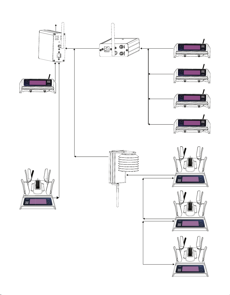
The AROYA system works in a Bluetooth®mesh network. A Bluetooth network allows data and
files to be transferred from one system to the other through wireless transmission. The AROYA
system components are FCC approved (Class A) and can communicate wirelessly between
each other. The Sensor Station/Sensor Nose can communicate data to the Router/Router
Climate or Gateway if close enough for the transmission to occur. The Sensor Station/Sensor
Base can also transmit data to each other on its way to the Gateway. Routers are used as range
extension for the network to help transmitt data from the Station/Nose units that are located
furthest from the Gateway. Figure1 shows a diagram of an AROYA mesh network.

2
INTRODUCTION
G—Gatway
R—Router/Router Climate
S—Sensor Station/Nose
R
R
R
R
G
R
S SS
S
S SS
SS
S
S
S
SS
SSSS
S
SSSS
S
SS
S
S
S
S
Figure1 AROYA system Bluetooth mesh network example

3
AROYA
2. OPERATION
Please read all instructions before operating the AROYA to ensure it performs to its
fullpotential.
PRECAUTIONS
METER sensors are built to the highest standards, but misuse, improper protection, or
improper installation may damage the sensor and possibly void the manufacturer’s warranty.
Before integrating AROYA into a system, make sure to follow the recommended installation
instructions and have the proper protections in place to safeguard sensors from damage.
2.1 INSTALLATION
Follow the steps listed in Table 1 to set up the Gateway.
Table 1 AROYA Gateway (H210) Installation
Tools Needed
Cordless drill
Screw driver
Screws
Mounting bracket (optional)
Preparation
Consider the Surroundings
Locate the Gateway in a closet or office with internet access for POE. The site
network infrastructure will determine what installation method is required
so the Gateway can communicate with other parts of the system. If this is not
possible, locate the Gateway wherever there is access to connections required to
establish communication.
The Gateway needs to be close enough to the Router(s) for the signal from the
Router to reach the Gateway.
Check Sensor Functionality
If the gateway is being connected to the existing network, plug the POE
connector wire into the wall port. Plug the other end of the connector cable
into the Gateway.
If the Gateway is not in a closet, plug one end of a POE injector into an Ethernet
port and power outlet and the other end into the Gateway.
After the Gateway is plugged in, look at the bottom where the cable is plugged
in and check for LED lights.
An LED light on the front/top flashes orange (Figure7) and and indicates there
is an active connection and the LED light on the back/bottom glows red if the
device is powered on and has an active connection.
NOTE: The LED on the front/top may flash green if the internet connection is slow.Both
green and orange flashing LED indicate an active connection.

4
OPERATION
Table 1 H210 Gateway Installation (continued)
Mounting
METER recommends mounting the Gateway on a wall with the cable ports at
the bottom.
Punch holes in the bottom of the mounting bracket. Make the holes large
enough to countersink the screws so the heads are below or flush with the
bracket surface.
Use a cordless drill with screwdriver attachments to screw the mounting
bracket to the wall.
NOTE: Countersink the screws so the screw head does not interfere with sliding the
Gateway into the bracket.The screw heads should be below or flush with the bracket
surface so the Gateway will not slip into the mounting bracket properly and may scratch
the surface of the Gateway.
The Gateway can also be located on a table or desk.
Configuration All system configuration work is done at METER before installation occurs at
the customer site.
Connecting
The devices must be powered on for the system to function. Once the devices
have been installed and properly powered, the system will automatically begin
communication with the user’s server (assuming the user has successfully set
up their AROYA cloud services account).
Verify the Router is connected to the internet and functional by looking for a
steady red LED light on the surface shown in Figure6.
Follow the steps listed in Table 2 to set up the AROYA Router.
Table 2 Router (H110) Installation
Preparation
Consider the Surroundings
METER recommends installing the Router in the center of each room of the
greenhouse to facilitate quality communication to the Gateway.
The Router should be in an area where the environment is as consistent as
possible. If a fogger is set up in the center of a room, set up the Router in a
location away from the fogger.
Mounting The Router (H110) has no installation location stipulations. METER
recommends installing the Router in a hallway.
Configuration All system configuration work is done at METER before installation occurs at
the customer site.
Connecting
Connect Router to Internet and Verify
Connect a CAT 5/6 Ethernet cable (or better) to the Router (Figure7) injector
module.
Verify the Router is connected to the internet and functional by looking for a
steady blue LED light on the surface shown in Figure7.

5
AROYA
Follow the steps listed in Table 3 to set up the AROYA Router Climate.
Table 3 Router Climate (H111) Installation
Tools Needed
Grow light hanger (e.g., rope ratchet clip hanger)
Chain/cable/rope
Preparation
Consider the Surroundings
METER recommends installing the Router Climate in the center of each room
of the greenhouse to facilitate quality communication to the Gateway.
The Router Climate should be in an area where the environment is as
consistent as possible. If a fogger is set up in the center of a room, set up the
Router in a location away from the fogger.
Mounting METER recommends installing the Router Climate in the center of each room
of the greenhouse to facilitate quality communication to the Gateway.
Configuration All system configuration work is done at METER before installation occurs at
the customer site.
Connecting
Connect Router to Internet and Verify
Connect a CAT 5/6 Ethernet cable (or better) to the Router Climate and to an
Ethernet injector module.
Verify the Router Climate is connected to the internet and functional by looking
for a steady blue LED light on the surface shown in Figure7.
Follow the steps listed in Table 4 to set up the AROYA Sensor Station.
Table 4 H310 Sensor Station Installation
Preparation
Consider the Surroundings
The Sensor Station should be set up at predetermined intervals along the table
where plant cubes or coco bags are located.
Check Sensor Functionality
Press function button until the LED flashes green.
Mounting Insert plant cubes or a coco bag into the sensor station and set the sensor
station on the table or shelf with other plants.
Configuration All system configuration work is done at METER before installation occurs at
the customer site.

6
OPERATION
Table 4 H311 Sensor Station Installation (continued)
Connecting
Connect Router to Internet and Verify
The Sensor Station is shipped to the customer in SLEEP mode, indicated by a
solid red STATUS LED light.
To wake the Sensor Station up, press the button (Figure9) one, two, or three
times to trigger the green LED. The device has enetered the ON mode when the
STATUS LED shows solid green.
NOTE: The unit toggles between ON and SLEEP mode after the button is pressed three
times.It remembers when the three button presses happen,even if they are days apart. If
the button is pressed once today,once tomorrow,and once the following day, the base will
either turn ON or go into SLEEP mode, depending on what state it was in prior to the third
button press.
Follow the steps listed in Table 5 to set up the AROYA Sensor Station.
Table 5 H311 Sensor Nose Installation
Tools Needed AROYA Sensor Nose
Preparation
Consider the Surroundings
The Sensor Nose is used with slabs or larger substrate types. The TEROS 12
needles are inserted into the slabs or larger substrate. Make sure there is
adequate table space near the slabs or larger substrate to place the Sensor
Nose on so enough light can reach the solar sensors to recharge battery..
Check Sensor Functionality
Press the function button (Figure11) until the LED flashes green.
Mounting Insert sensor into slabs or larger substrate types.
Configuration All system configuration work is done at METER before installation occurs at
the customer site.
Connecting
Connect Router to Internet and Verify
The Sensor Station is shipped to the customer in SLEEP mode, indicated by a
solid red status LED light on the end where the cable is connected.
To wake the Sensor Station up, press the button one, two, or three times to
trigger the green LED. Status LED showing solid green indicates the device has
entered the ON mode.
NOTE: The unit toggles between ON and SLEEP mode after the button is pressed three
times.It does not matter when the three button presses happen. For instance, if the button
is pressed once today, once tomorrow,and once the following day, the base will either turn
ON or go into SLEEP mode, depending on what state it was in prior to the third button press.

7
AROYA
3. SYSTEM
This section describes the specifications, components of the AROYA Gateway, Router, Router
Climate, Sensor Station, and Sensor Base.
3.1 SPECIFICATIONS
MEASUREMENT SPECIFICATIONS
ATMOS 14 Temperature and Relative Humidity (RH) Sensor
Relative Humidity (RH)
Range 0–100% RH (0.00–1.00)
Resolution 0.1% RH
Accuracy Sensor measurement accuracy is variable across a range
of RH. Refer to the chart in Figure2.
Figure2 RH sensor accuracy
Equilibration Time
(τ,63%)
<40 s (response time in 1 m/s air stream)
Hysteresis <1% RH, typical
Long-Term Drift <0.5% RH/year, typical
Temperature
Range –40 to 80 °C
Resolution 0.1 °C

8
SYSTEM
Accuracy Sensor measurement accuracy is variable across a range
of temperatures. Refer to the chart in Figure3.
Figure3 Temperature sensor accuracy
Equilibration Time
(τ, 63%)
<400 s (response time in 1 m/s air stream
Long-Term Drift <0.04 °C/year, typical
Vapor Pressure
Range 0–47 kPa
Resolution 0.01 kPa
Accuracy Sensor measurement accuracy is variable across a range
of temperatures and RH. Refer to the chart in Figure4.
Figure4 Vapor pressure sensor accuracy
Barometric Pressure
Range 50–110 kPa
Resolution 0.01 kPa
Accuracy ±0.4 kPa

9
AROYA
TEROS 12 Soil Moisture,Temperature, and Electrical Conductivity (EC) Sensor
Volumetric Water Content (VWC)
Range
Mineral soil calibration 0.00–0.70 m3/m3
Soilless media
calibration
0.0–1.0 m3/m3
Apparent dielectric
permittivity (εa )
1 (air) to 80 (water)
NOTE: The VWC range is dependent on the media the sensor is calibrated to. A custom calibration will
accommodate the necessary ranges for most substrates.
Resolution 0.001 m3/m3
Accuracy
Generic
calibration
±0.03 m3/m3typical in mineral soils that have solution EC <8
dS/m
Medium specific
calibration
±0.01–0.02 m3/m3in any porous medium
Apparent dielectric
permittivity (εa )
1–40 (soil range) , ±1 εa(unitless)
40–80, 15% of measurement
Dielectric Measurement Frequency
70 MHz
TEROS 12 Temperature
Range −40 to +60 °C
Resolution 0.1 °C
Accuracy ±0.5 °C from −40 to 0 °C
±0.3 °C from 0 to +60 °C
Bulk Electrical Conductivity (EC) (TEROS 12 Only)
Range 0–20 dS/m (bulk)
Resolution 0.001 dS/m
Accuracy ±(5% + 0.01 dS/m) from 0–10 dS/m
±8% from 10–20 dS/m
10
SYSTEM
COMMUNICATION SPECIFICATIONS
Output
Gateway Ethernet (POE)
Wireless communication Bluetooth mesh (Gateway, Routers, Sensors)
Sensor types SDI-12 based
Antenna
Manufacturer Raltron
Model number RST-W2-P-110-SMA-H
Gain 4.15 dBi
vertically polarized, dipole professionally installed
NOTE: This radio transmitter IC-5123A-MGM12P0 has been approved by Innovation, Science and Economic
Development Canada to operate with the antenna types listed below, with the maximum permissible gain
indicated.Antenna types not included in this list that have a gain greater than the maximum gain indicated for
any type listed are strictly prohibited for use with this device. Maximum Gain:4.15 dBi Vertically polarized, dipole.
PHYSICAL SPECIFICATIONS
Dimensions
Antenna
(Gateway, Router, Router Climate,
Sensor Station, Sensor Nose)
11.5 cm (4.53 in)
NOTE: Antenna is positioned straight out adding to the total length.
Gateway
Length 14.5 cm (5.71 in)
Width 10.5 cm (4.13 in)
Height 4.5 cm (1.78 in)
Router
Length 14.6 cm (5.75 in)
Width 10.2 cm (4.00 in)
Height 14.3 cm (5 63 in)
Router Climate
Length 15.5 cm (6.10 in)
Width 8.5 cm (3.35 in)
Height 3.7 cm (1.46 in)

11
AROYA
ATMOS 14 with radiation shield
Diameter 10 cm (3.94 in)
Height 8.5 cm (3.35 in)
Sensor Station
Length 23.5 cm (9.25 in)
Width 18.0 cm (7.48 in)
Height 12.3 cm (4.84 in)
TEROS 12
Length 9.4 cm (3.70 in)
Width 2.4 cm (0.95 in)
Height 7.5 cm (2.95 in)
Needle length 5.5 cm (2.17 in)
Sensor Station
Length 6.99 cm (2.75 in)
Width 18.00 cm (7.10 in)
Height 3.02 cm (1.19 in)
TEROS 12
Length 9.4 cm (3.70 in)
Width 2.4 cm (0.95 in)
Height 7.5 cm (2.95 in)
Needle length 5.5 cm (2.17 in)
Operating Temperature Range
Minimum –40 °C
Typical 50 °C
Maximum 80 °C
NOTE: Sensors may be used at higher temperatures under certain conditions; contactCustomer
Supportfor assistance.
Cable
CAT 5E or better (Gateway)
CAT 7 or better (Routers)

12
SYSTEM
Connector Types
Gateway power RJ 45 Ethernet cable
Router power RJ 45 Ethernet cable
Sensor Station/ Sensor
Nose power
RJ 45 Ethernet cable
ATMOS 14 and TEROS12
sensor connection
M8 circular female plug and female thread (Sensor State/
Sensor Nose, Router, Router Climate)
Communications port M8 circular female plug and female thread (Sensor State/
Sensor Nose, Router, Router Climate)
ELECTRICAL CHARACTERISTICS
Power
Lithium-ion (Li-on)
rechargeable battery
Battery cannot be replaced by the user.
NOTE: The Gateway device does NOT have a battery. It is powered
over Ethernet
Power Over
Ethernet(POE)
42.5–57.0 V, up to 25.5 W
CAUTION: If using a nonmanufacturer supplied POE device to power this system,ensure that the voltage rating
does not exceed the recommended values stated above.The injector module used must comply with IEEE
802.3af and must be able to supply at least 24 W for the Gateway to function as intended.
COMPLIANCE
Manufactured under ISO 9001:2015
3.2 COMPONENTS
This sections describes the components of the AROYA system.
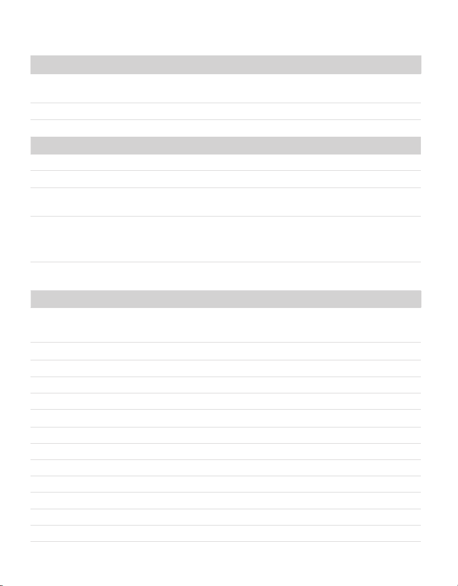
3.2.1 GATEWAY H210
The Gateway provides sensor readings received from either a Router/Router Climate
(Section3.2.2)or Sensor Station/Sensor Nose (Section3.2.3) to the AROYA app for the
customer to review.The indicator light flashes orange when the device is powered from a POE
switch. Ensure the device is powered by a device that supplies both Ethernet and power. The
cable must be an RJ 45 CAT 5E or better.
13
AROYA
The Gateway operates using the following components:
• Power over Ethernet (POE) module for continuous power
• 2.4-GHz Bluetooth low-energy chip antenna
Antenna
LED indicates
active internet
connection
(flashing orange)
NOTE: If the internet
connection is slow,
the light may flash
green instead of orange.
This also indicates
active connection.
Front/top cover
(end cap)
Ethernet
POE port
(RJ 45)
Figure5 AROYA Gateway—front/top view
14
SYSTEM
Antenna
Red LED
indicates
power status
Back/bottom
cover (end cap)
Figure6 AROYA Gateway—back/bottom view
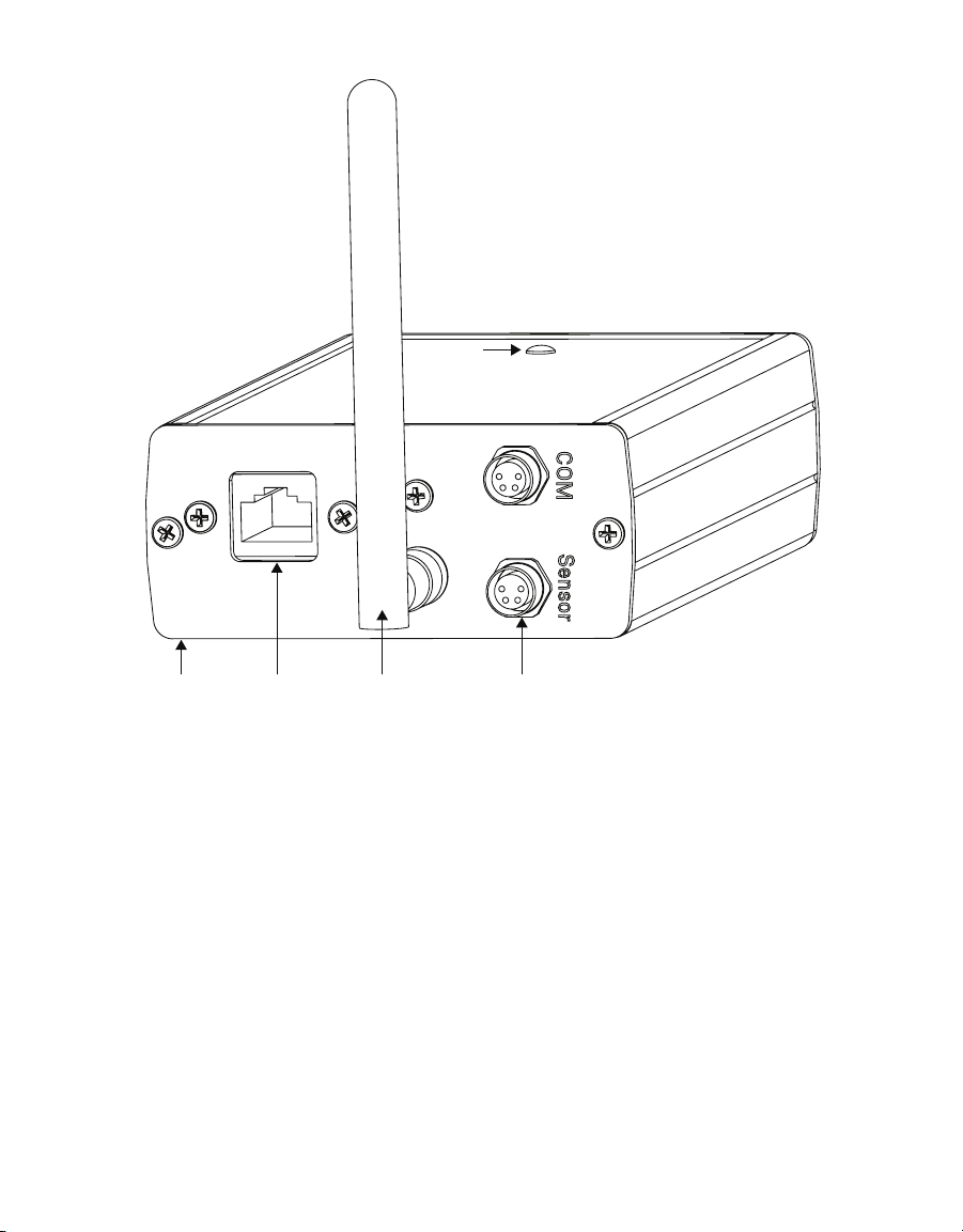
3.2.2 ROUTER H110 AND ROUTER CLIMATE H111
The AROYA Router/Router Climate receives data from the sensor stations and transmits
data to the gateway wirelessly. The Router acts as a range extension for the network and
funnels the data to the Gateway device. The Router operates on a Bluetooth Mesh network
and relies on an active POE connection to supply power to the device.
The Router and Router Climate both operate using the following components:
• POE module for continuous power
• Rechargeable lithium-ion battery for back-up power
• 2.4-GHz two-way antenna for Bluetooth communication
• 38.4-MHz oscillator for high frequency, precise timing reference
• 32.768-kHz oscillator for low-frequency, low-energy timing reference
15
AROYA
Blue LED
indicates
power ON
AntennaFront/top
cover (end cap)
M8 connectorsEthernet
POE port
(RJ 45)
Figure7 AROYA Router—front/top view
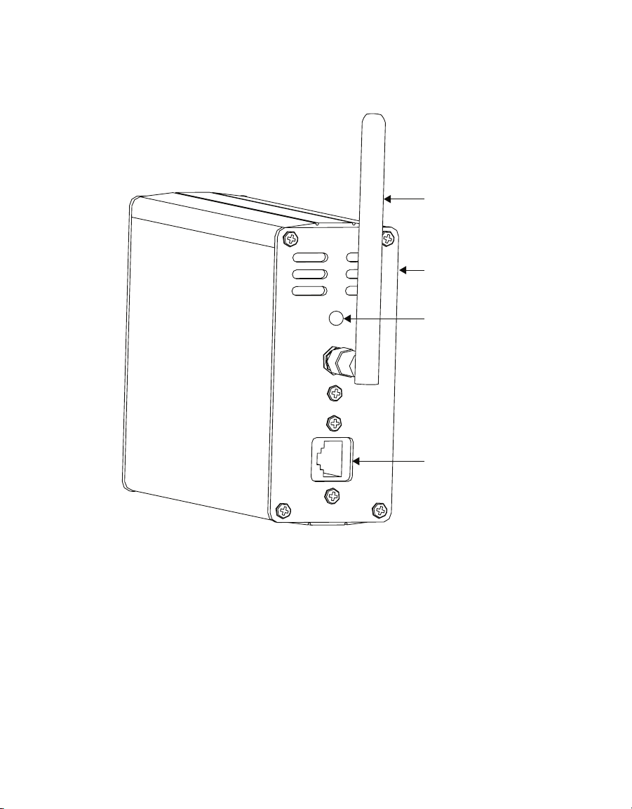
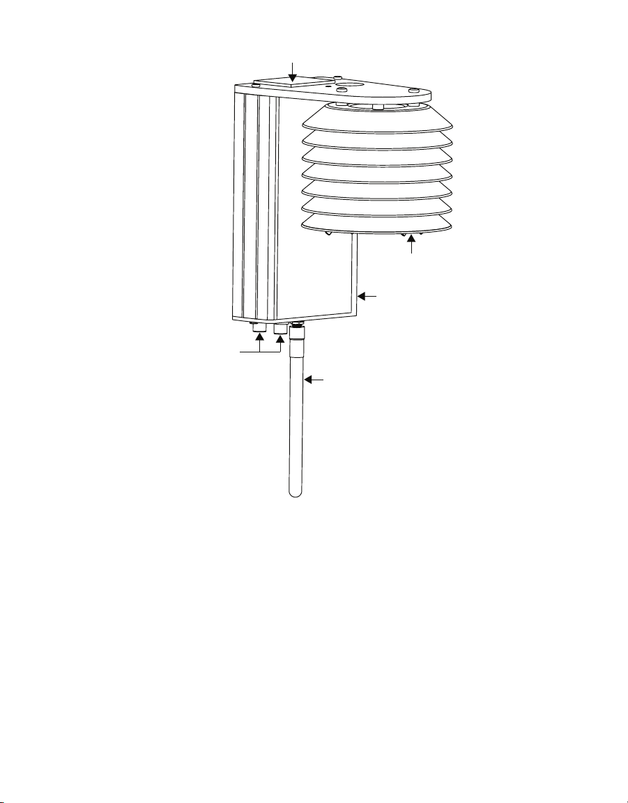
The AROYA Router Climate receives data from the Sensor Stations/Sensor Noses and
transmits data to the Gateway wirelessly. The ATMOS 14, located in a radiation shield and
attached to the Router Climate, collect microclimate data that is also transmitted to the
Gateway. The radiation shield comprises a mounting bracket and seven discs. The shield
prevents direct sunlight from coming into contact with the sensor. This isolation from
solar radiation prevents false readings of elevated temperatures, allowing for accurate
measurement of ambient air temperature.
16
SYSTEM
ATMOS 14 in
radiation shield
M8 connectors
Router
Solar panel
Antenna
Figure8 AROYA Router Climate with ATMOS 14 sensor
3.2.3 SENSOR STATION H310 AND SENSOR NOSE H311
Figure9 and Figure10 show the AROYA Sensor Station and Figure11 and Figure12 show the
AROYA Sensor Nose. Both the Station and the Nose contain a TEROS12 soil moisture sensor,
location for plant, communication components, and antenna to communicate data gathered by
the TEROS12 to the router or directly to the gateway if the base is close enough.
The Sensor Station and Sensor Nose both operate using the following components:
• Rechargeable lithium-ion battery
• Solar Panels for energy harvesting
• 2.4-GHz two-way antenna for Bluetooth communication
• 38.4-MHz oscillator for high frequency, precise timing reference
• 32.768-kHz oscillator for low-frequency, low-energy timing reference

17
AROYA
Fuction
button
Solar panel
TEROS 12
sensor
Antenna
Figure9 AROYA sensor station with TEROS 12 sensor
Table of contents


