MetLogix Mx200 User manual


2
Table of Contents
1 Getting Started ..................................................................................................................................................3
1.1 Shipping Contents……………………………………………………………………….3
1.2 Mx200 Specifications…………………………………………………………………..4
1.3 Hardware Installation and Connections……………………………………….4
2 Mx200 Software Setup ......................................................................................................................................9
2.1 Powering on the Mx200……………………………………………………………….9
2.2 Mx200 Keypad and Touch Screen Control………………………………….10
2.3 Supervisor Password Protection………………………………………………...12
2.4 The Setup Menu…………………………………………………………………………13
2.5 System Settings Import/Export…………………………………………………..14
2.6 Encoder Settings…………………………………………………………………………14
2.7 Optical Edge Sensor Setup and Calibration…………………………………17
2.8 Display Resolution and Format…………………………………………………..20
3 Error Correction...............................................................................................................................................22
3.1 Squareness Correction………………………………………………………………22
3.2 Linear Error Correction(LEC)……………………………………………………..23
3.3 Segmented Linear Error Correction(SLEC)…………………………………24
3.4 Non Linear Error Correction(NLEC)……………………………………………25
4 Additional Setup Screens.................................................................................................................................28
4.1 Desktop……………………………………………………………………………………29
4.2 Locks……………………………………………………………………………………..…31
4.3 Measure……………………………………………………………………………..……31
4.4 Printouts…………………………………………………………………………….……32
4.5 Programs……………………………………………………………………………….…32
4.6 Quick Keys……………………………………………………………………………..…33
4.7 RS232………………………………………………………………………………….……34
4.8 Sounds……………………………………………………………………………..………35
4.9 Tolerance………………………………………………………………………….………36
Mx200 Setup Guide
3
1Getting Started
The following sections will describe the package contents, readout specifications, mounting options, and
basic machine hardware connections for the Mx200 readout.
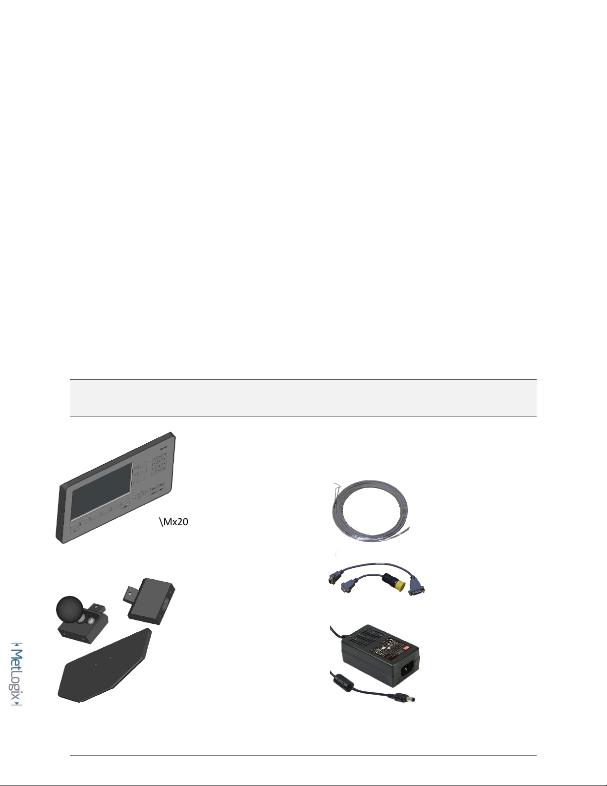
1.1 Shipping Contents
The following components are part of your Mx200 digital Readout kit:
-Mx200 Device
-Machine mounting option(Ball, Block, or Stand)
-Power supply module and Line Cord(US 2-LINE)
-Fiber optic accessories(optional)
-Encoder adapter cables(optional)
Note: It may be helpful to save the Mx200 packaging in the event the device needs to be returned to the
manufacturer for repair or requires transport to a new location.
\Mx200 Device \Fiber Optic Accessories
\Adapter Cables
\Mounting Option \Power Supply

4
1.2 Mx200 Specifications
Display: 7" Color 1024 X 600 LCD, with an LED backlit capacitive touch screen.
Power: Power supply(included): 100-240VAC, 50/60Hz, 3.0A. Power Input to Mx200: 12V.
Agency Approvals: CE
DRO Dimensions: 286mm wide x 51mm deep x 162 mm high
DRO Baseplate Dimensions: 120mm wide x 125mm deep x 9.5mm high
Mounting Options:
OEM mount: Two Riser Blocks providing up to 4 distinct viewing angles, using (2) M6 threaded holes,
spaced 38mm.
RAM ball mount: One Riser Block with 1.5” RAM Ball.
Base plate: Base Plate with two Riser Blocks providing up to 4 distinct viewing angles from the base.
1.3 Hardware Installation and Connections
The following section describes how to connect;
Mounting hardware(A)
Power Connection(B)
Encoder Connections(C)
Optical Edge Cabling(D)

5
A. Mounting hardware installation:
Note: It is important that the Mx200 device is operated from a secure and rigid mounting location.
While the supplied Metlogix mounting hardware may serve as an adapter piece toward that installation,
it is the installation technicians’ responsibility to ensure complete and safe installation of the device.
•Select the appropriate mounting method from the 3 options below.
OEM Mount Installation:
Using a 3MM Allen wrench and the supplied M6 screw, connect the riser block to the opening on the rear panel of
the Mx200. The hole spacing is 38MM with a ¼”-20 thread pattern. Screws required to connect the OEM mount to
the machine mount are not included in the Mx200 mounting kit.
Ball Mount Installation(1.5” Ball):
Using a 3MM Allen wrench and the supplied M6 screw, connect the riser block/ball mount module to the opening
on the rear panel of the Mx200.

6
Base Mount Installation:
Using a 3MM Allen wrench and the supplied M6 screw, connect the riser block to the opening on the rear panel of
the Mx200.
Using a 4MM Allen wrench and the (2) supplied M6 screws, connect the supplied stand to the riser block.
•Complete the Mx200 readout installation according to the recommended mounting
technique for the measuring system being used.
•For standard “benchtop” installations place the Mx200 readout on a flat stable surface
within reasonable operating distance from the measuring system.
B. Power Connection:
•Attach the supplied 12V(Positive Tip)power supply connector to the power input port on
the Mx200 readout.
7
•Connect the supplies 2-wire line cord cable to a stable 110/220 AC power source.
•IMPORTANT: The Mx200 digital readout is NOT designed to be powered off instantaneously by
removal of the power supplied to the unit. As such the power supply to the Mx200 should be
connected directly to a power source, and not to an intermediary power switch. To power off
the Mx200 correctly long press the power button on the front keypad and press the “Power Off”
button displayed at the right side of the main Mx200 screen.
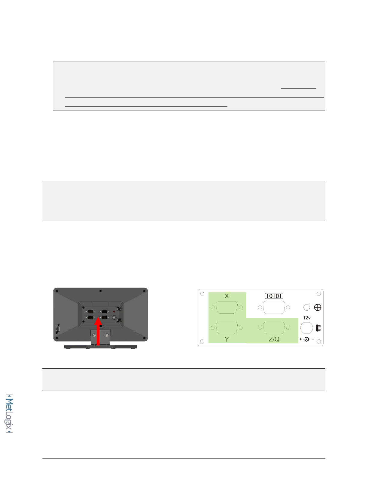
C. Encoder connections:
The Mx200 is designed to accept input from 1, 2, or 3 analog or TTL encoders. These encoders are
typically arranged according to the major axis of the measuring system in which they are mounted; X, Y,
and Z(or Q Rotary/Protractor).
IMPORTANT: All Mx200 readouts are designed to accept either TTL or Analog input from the connected
encoder. It is however critical that the correct signals be connected between the encoder and the
Mx200 to avoid damage to the MX200 and/or the encoder. Please ensure that the encoder connections
to the Mx200 have been verified as compatible by an authorized Metlogix OEM prior to installation.
•Ensure that the Mx200 is powered off prior to connecting any encoders.
•Locate encoder terminations from the measuring system and connect them to the X, Y
and Z(Q) encoder inputs on the back of the Mx200 as seen below.
NOTE: Secure all encoder connections tightly to the standoffs at the input connector to ensure complete
communication between the encoder and the Mx200.

8
D. Optical Edge Cables
Optical Comparator Systems can be equipped with or without Optical Edge Sensor capability. The Mx200
is available either with or without the required electronics to support these sensors. This can be
determined by inspecting the rear panel of the readout chassis and checking whether the (2) fiber optic
terminals are present.
NOTE: Please contact your Metlogix OEM or representative in the event you require optical edge
support but your Mx200 Readout is not equipped with the required optical edge interface.
•The Mx200 is equipped with (2) optical inputs for receiving light levels from the Optical
Comparator. Connect the Screen and Reference channel from the optical comparator to the
Mx200 Optical Inputs.
Reference Channel: The reference channel should be connected from the Comparators’ lamp housing
light source to the lower connector on the back of the readout.
Screen Channel: The screen channel should be connected from the fiber optic termination at the
Comparators’ measuring screen to the upper connector on the back of the readout.
Screen Sensor
Reference Sensor

9
A. USB and RS232 Port Connections
•The Mx200 is equipped with both a USB port and a 9 pin general purpose IO port to support
data transfer to external storage drives, and PC systems(RS232). These connections will be
described later in this document within the setup sections for Printing, and Data and Settings
transfer to USB.

10
2Mx200 Software Setup
The following section will describe the basic setup parameters for configuring the Mx200. Not all setup
screen items will be addressed in this section. Additional setup screen settings and procedures will be
described in Section 4, “Additional Setup Screens”.
QUICK START: Follow the Green Ribbons through this document for the steps to Quick Start Basic
Setup of the Mx200 readout. While these steps can help quickly achieve initial machine setup, the
additional settings and features described below can always be configured alongside these basic
setup steps.
2.1 “Power On” the Mx200 readout.
Press the “Power Button” located in the bottom left corner of the Mx200 keypad.
Allow Mx200 boot sequence to complete. Once the Mx200’s main DRO view is displayed you can
continue with the setup procedure.
2.2 Navigating the Mx200 with Keypad and Touchscreen Controls
The Mx200 User Interface can be navigated by touchscreen control, by keypad button control, or a
combination of both. This dual input mode support applies to both the setup screen menu’s as well as
the main measuring modes of the readout

11
Description of keypad button functions can be seen below;
Keys Function
Number Pad Enter numeric digits, decimal points, and sign(+/-)into the current field.
Command Keys
Enter - Select data entry field or setup menu item.
Finish -
Confirm selected function or setup menu item.
Cancel -
Navigate up one level from current setting menu.
Quit –
Exit the current setting screen back to the top level settings screen.
Arrow Keys Navigate the settings menu screens. The left and right arrows go in a level, or
out a level. The up and down arrows move the current selection up/down.
Power Key Single Press to Power On. When On, Single Press for Screen Off, Long Press
for Power Off.
Soft Keys(1-6) Executes the softkey button commands/selection displayed above the key.
DRO Keys Execute X/Y/Z/Q zerroing funciton. Select functions as vertical softkeys.
Menu Button Displays or advances the Softkey Menu. Long press to enter Mx200 Setup.

12
ENTERING SETUP: Enter the Mx200 Information and Setup Screens by pressing either the touchscreen
“Mx” button in the top left corner of the screen, or by pressing the “Menu Button” and then choosing
the “Mx” softkey button.
Once in the Information screen, the first menu item called “Setup” will grant access to the setup menu
items. The remaining items listed provide information about the Mx200 readout itself, including;
Menu Item Description
Setup Press to access the main Setup Menu.
13
Language Press to select desired display language.
Product Displays the Product Description.
Software Version Displays the Mx100/Mx200 software version.
Release Date Displays the Release Date of the Mx200 software currently running.
Copyright Displays Metlogix Copywrite Information.
Options Displays the currently enabled software/hardware options in the system.
Hardware version Displays version numbers for installed hardware code. App, Boot, FPGA, MB,
and Edge.
Serial Number Displays the serial number of the Mx200 unit in the format[XXXX-XXXX-XXXX].
Exit Settings Press to Exit the Mx200 Readout Application.
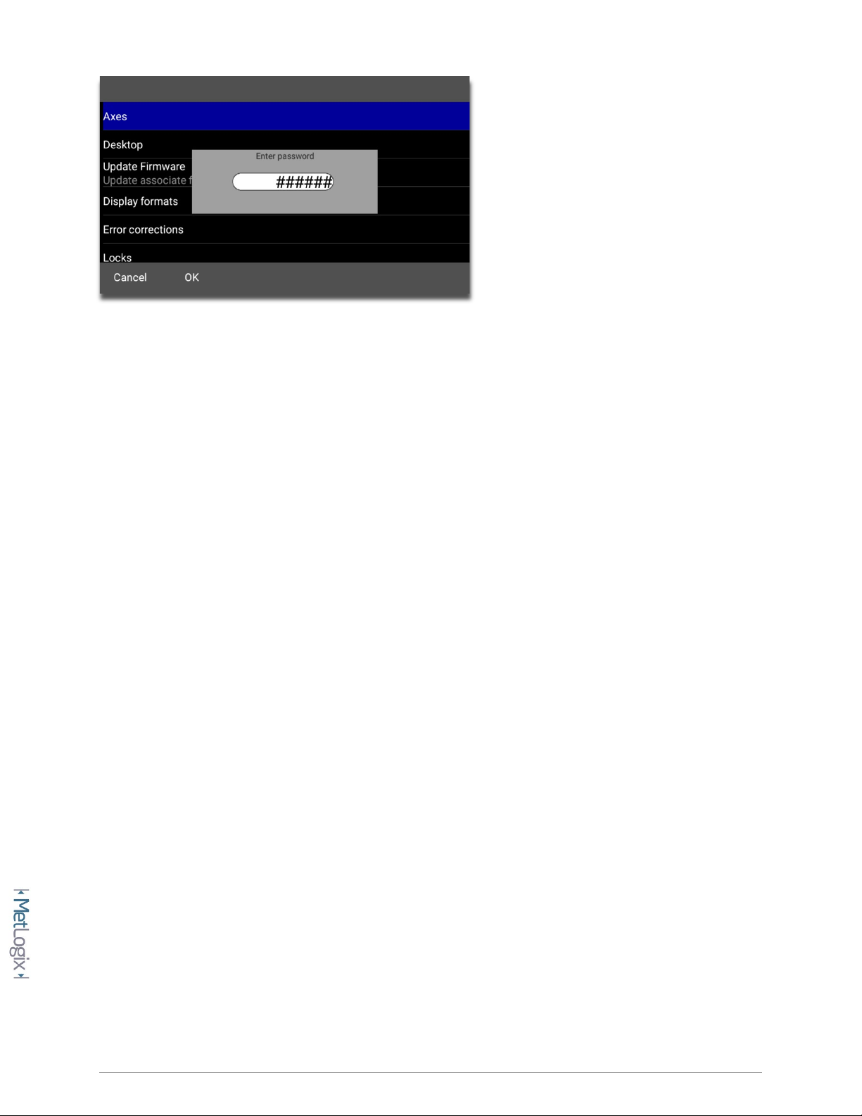
2.3 Supervisor Password Protection
IMPORTANT: Many of the settings configured in the Mx200 require password authentication in order to
modify them. In general, settings relating to the initial configuration and calibration of the readout will
be password protected. Settings that behave more like User Preferences are typically not password
protected.
Settings in the setup menu that appear with a blue “lock” icon require password entry
prior to modification. Most important machine configuration settings fall into this category.
Use the procedure below to enter the Supervisor Password and unlock the system setup
screens.
14
To enter the Mx200 password;
•Navigate to the Setup Menu and Scroll to the Password menu item.
•Press Enter and then key in “XXXXXX” using the numeric keypad.
•Press “Finish” to confirm the entered password.
•A small message should appear briefly indicating “supervisor mode”.
•To Remove the password, simply highlight the “Password” settings item and press the
“Right Arrow” key. A small message should appear indicating “user mode”.
2.4 The Setup Menu
Most setup parameters in the Mx200 are configured using screens and data entry fields accessed via the
setup menu items. Highlighting a setup menu items and pressing “Enter” grants access to that menu
items’ submenu or displays a numeric entry field(or softkey option) for modification of that particular
parameter.
The Mx200 setup menu is easily navigated using the following step;
•Press the MENU key(Mx Button).
•Highlight the Setup Menu item and press “Enter”.
•Scroll to the desired setup screen and press “Enter”.
•Highlight the desired setup parameter and press “Enter”.
•Use the keypad for numeric entry, or the softkeys to select setting for that parameter.
•Press the “Finish” key until the Setup Menu is fully exited.
15
2.5 System Settings Import/Export
The Mx200 readout has the ability to Import or Export a System Settings file from an attached USB drive.
This allows for quick and convenient loading of previously configured setup parameters to an un-
configured Mx200 readout. This also allows backups of existing parameter sets to be stored for use on
another device, or as a settings backup for the current device.
To Import or Export an Mx200 settings file from the USB port;
•Put a USB storage device into the USB port of the device. If Importing a settings file, ensure the
Mx200 settings file is at the root of the USB device.
•Press the MENU key(Mx Button).
•Highlight the Setup Menu item and press “Enter”.
•Scroll to the “System” setup screen and press “Enter”.
•Select the “Import Settings” softkey to Load a settings file from USB, or the “Export Settings”
softkey to store your current settings to the USB device
•Confirm your selection by Pressing the OK or Cancel softkey
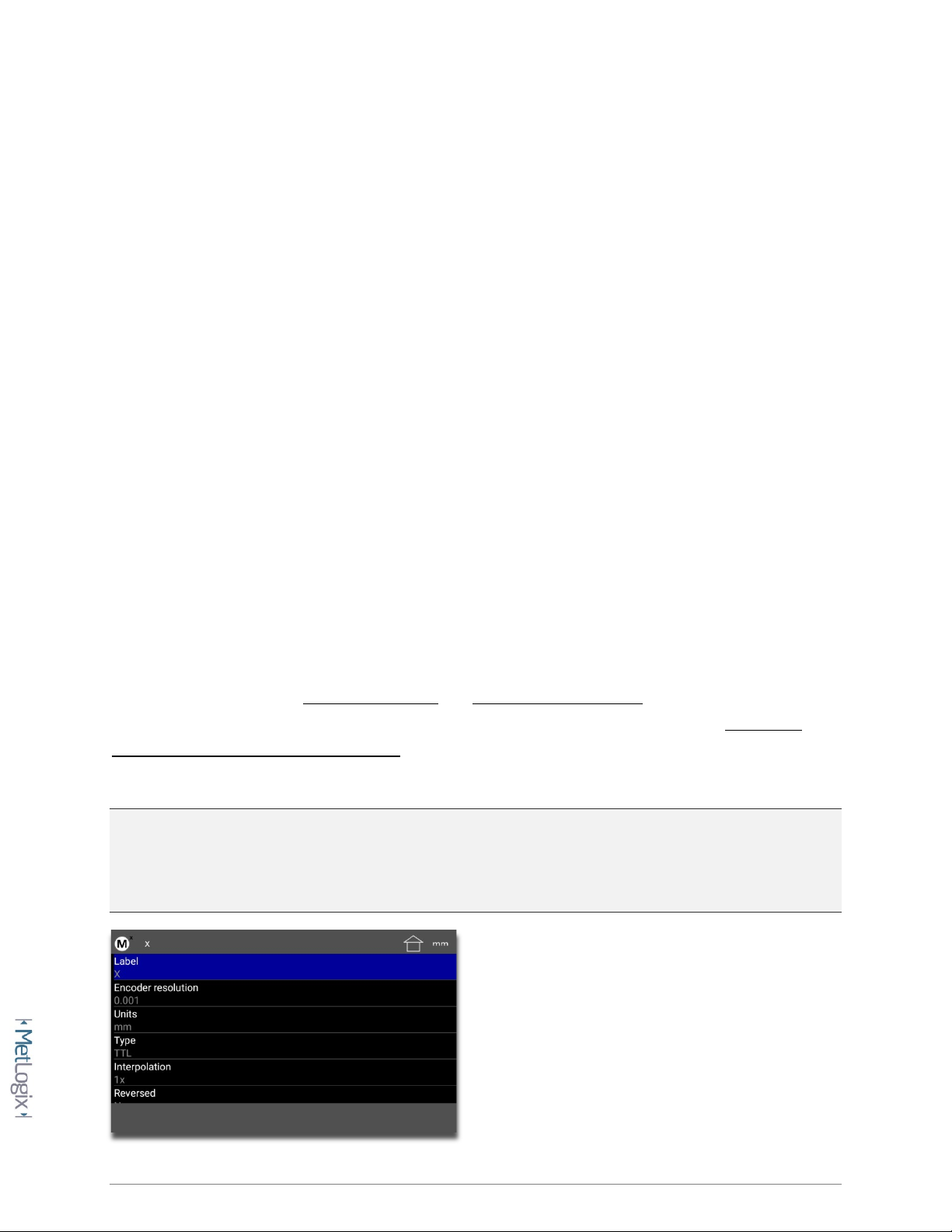
2.6 Encoder Settings
Proper configuration of the encoders in the Mx200 setup is critical for achieving accurate measuring
results from your machine. Encoder Resolution and Encoder Count Direction are the two most
important settings for achieving this accuracy. Additionally, systems requiring advanced Stage Error
Correction methods such as SLEC or NLEC will require that Reference Marks also be configured, to
ensure reliable identification of the machine coordinate zero position each time the machine is used.
NOTE: All settings described below apply to the X, Y, and Z axis setup in the Mx200. The descriptions
below may reference a particular axis but are intended to apply to each axis, X, Y, or Z. The Q(Rotary)
Axis Encoder Resolution contains an additional teach function which will be referenced separately
below.

16
Specify the signal type, encoder resolution, and direction for the encoder being configured. Verify
that the encoder displacement and direction of travel are correct using some know standard of
size and observing the major directions for part coordinates relative to the measuring image of
the system.
(X)Axes Menu Description
Label Press Enter to specify a new single character Axes Label for the selected axis.
Encoder Resolution Press Enter to display the encoder resolution entry field for the selected axis.
Enter the desired encoder resolution and press “OK” to confirm.
Units Select the IN or MM softkey to specify the Unit type for the entered encoder
resolution(specified above).
(Signal)Type
Select the softkey for the encoder type you are interfacing to the Mx200.
-TTL/1VPP/11uA/Nikon/Mitutoyo
Interpolation
Select the softkey that corresponds to the desired Interpolation Factor for
your Analog encoder. Consult the encoder specification for information on
what Resolution and Interpolation combination to use. The Mx200 supports
1X, 5X, 10X and 16X Interpolations Settings.
Reversed Select the Yes or No softkey to invert the counting direction of your encoder.
To reverse the direction from “current”, simply invert the Yes/No settings.
Startup Zero
Select the desired Startup Zeroing method based on the encoder reference
mark technology and machine configuration requirements for the
installation.
-None/Hardstop/One Ref/2 Ref(Distance Encoded)
Ref Mark Direction
Select the Positive or Negative Pulse softkey to invert the reference mark
active state for detection. To reverse the direction from “current”, simply
invert the Positive/Negative settings.

17
Ref Mark Source Only relavent when “Distance Encoded(2Ref)” startup zeroing method is
configured. Specifies whether the Standard or Acurite Algorithm is used.
Ref Mark is Angular Select the Yes or No softkey to specify a ref mark configuration for rotary
encoded axes. Set to “No” for typical linear encoders.
Ref Mark Pitch Press Enter to set the Reference Mark Pitch as indicated by the specification
for your encoders.
Ref Mark Fixed
Increment
Press Enter to set the Reference Mark Fixed Increment as indicated by the
specification for your encoders.
Machine Zero Offset
Press Enter to display the Use Stage Position softkey or dialog option. Press
Enter to calculate the offset(in counts) between the startup zero postion and
the current stage position.
Report Scale Errors Select the “Yes” or “No” softkey to enable or disable scale error reporting.
To teach Q Axis Rotary Encoder Resolution:
•Access Setup and enter the Supervisor Password.
•Navigate to the Axes setup screen.
•Select the Q Axis menu item.
•Select the Encoder Resolution menu item.
•Press the Softkey labeled "Teach".
•Follow the on-screen prompts to teach Q.
A NOTE ABOUT STAGE CORRECTION AND REFERENCE MARKS: The SLEC and NLEC stage calibration
functions require that a repeatable startup zero position be established prior to calibration and each
time the Mx200 readout is started. This position can be established by configuring either Single, or Dual
Reference marks in the Encoder Setup Screen. When configured the operator will be prompted to cross
the reference marks for each enabled axis at startup.

18
Configure Machine Zero Offset and Verify Reference Mark Startup Position
•Configure and verify the correct encoder resolution and count direction for all axes.
•Set the Reference Mark type correctly for each encoder being configured.
•At the Main Mx200 Settings screen press the “Set Home Position” button located at softkey 1.
Pic
•Cross the reference marks for each enabled axis, as prompted.
•Position the stage at the desired startup zero position in each axis being configured. Place some
artifact within the measuring view and align it with the center crosshair position.
•Enter Setup, Axis Setup, Choose X Axis, and then select the Menu item called “Machine zero
offset”
•Press the “Use Current Position” button to set the offset(in counts) from the detected startup
encoder position to the current stage position.
•Repeat the previous (2) steps for each axis configured for reference marks.
•Restart the Mx200 and cross reference marks at startup. Position the crosshair at you
comparison artifact location and verify that the stage position reports zero in the readout for
each enabled axis.
•Drive to a new stage location and repeat the step above, again verifying machine zero at
startup.
2.7 Optical Edge Sensor Setup and Calibration
Note: Systems not equipped with an Optical Edge Sensor support can skip this section and proceed to
section 2.8. Systems equipped with Optical Edge support must have the Factory Option enabled prior to
proceeding. Verify using the following setup screen sequence;
Mx Button-->Setup-->Enter Password-->Factory Options-->Verify the Optical Edge item is set to “Yes”
Verify that the Screen and Reference Fiber Optic cables are mounted on the measuring machine
according to the manufacturer specification and connected to the correct fiber optic inputs on the
Mx200 readout. See section 1.3 D for more information. Perform the reference fiber adjustment and
optical edge sensor calibration steps below.

19
Adjusting reference fiber positioning
•Access the Optical Edge setup screen at;
Mx Button-->Setup-->Optical Edge
•Press soft key 2 to access the light level “Install” screen.
•Follow the instructions in the prompt, adjusting the position of the reference fiber in the
machine lamphouse until the Screen Sensor Level and Reference Sensor Level are “nearly”
equal. These two values do not need to be exactly the same but should be close.
Important: Both the Screen Sensor Level and Reference Sensor Level should be below a value of
“1000”. If the Reference Sensor Level is at 1000 you made need to position the lamphouse fiber
pointing further away from the light source or add an additional attenuation device at the fiber
optic termination.
Calibrating the Optical Edge Sensor
•Select the Optical Edge teach button from the Probe Menu(softkey 4).

20
•Follow the instructions displayed in the teach dialog, positioning your sensor in the light, the
dark, and finally in the light again.
•Once the teach is complete press the Done button to finish the edge sensor calibration
procedure.
The system should not be prepared to enter edge positions with the Auto Enter and Manual Edge probe
mode.
Adding Additional Magnifications
In some cases more than one lens(magnification) will be used with a given measuring system. Each one
of these lenses can be calibrated independently for the storage and recall of taught edge values, lens to
crosshair offsets, and distance calibration(edge correction).
New magnifications are added and configured via the Optical Edge setup screen
Mx Button-->Setup-->Optical Edge
Add a new magnification by pressing “+” button(softkey 1).
Screenshot
Name the new magnification and press OK. You should now be viewing the settings for the new
magnification.
Mag Menu Item Description
Name Displays the name assigned to the current magnification. Press to rename
the magnification.
(X/Y)Edge to Xhair
Offset
Press to Enter the X and Y offset between the current optical edge sensor
position and the current position of the screen crosshair.
Other manuals for Mx200
1
This manual suits for next models
1
Table of contents


