Metos BH/IN 2500 User manual

INDUCTION COOKERS
Install-Line
BH/IN 2500
SH/IN 3500
SH/IN 5000
SH/WO/IN 3500
SH/WO/IN 5000
SH/WO/IN 8000
Installation and Operation Manual

-1-
Content
1Generalremarks.........................................................................................................2
1.1 Descriptionofdangersigns.......................................................................................2
1.2 Purposeofinductioncookers....................................................................................3
2Descriptionofproducts...............................................................................................4
2.1 Scopeofsupply........................................................................................................4
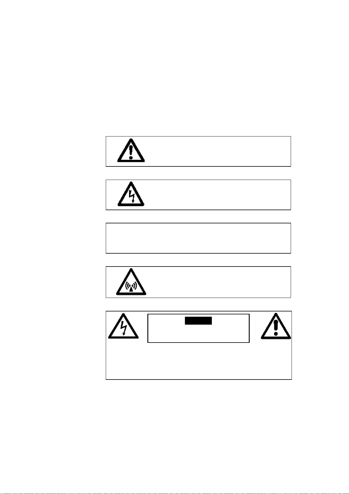
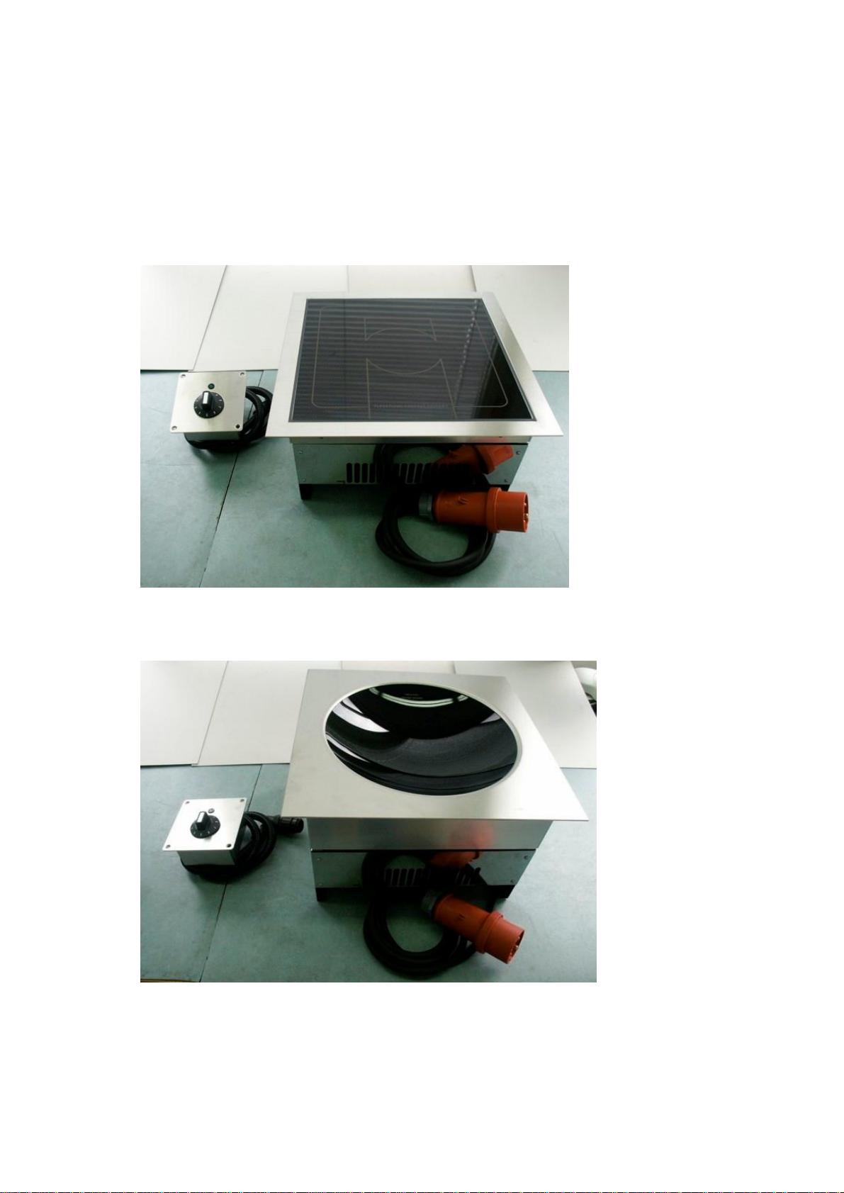
2.2 Products...................................................................................................................4
2.3 Install-unitsataglance.............................................................................................5
2.4 Technicalspecifications............................................................................................6
3Installation...................................................................................................................8
3.1 Scopeofdelivery......................................................................................................8
3.2 Requirementsofinstallation.....................................................................................8
3.3 Definitionofinterfaces.............................................................................................8
3.4 Installationclipping BH/IN2500..............................................................................9
3.5 Installationclipping SH/IN3500 andSH/IN5000..................................................10
3.6 Installationclipping SH/WO/IN3500, SH/WO/IN5000 andSH/WO/IN8000.......11
3.7 Advice forinstallation............................................................................................11
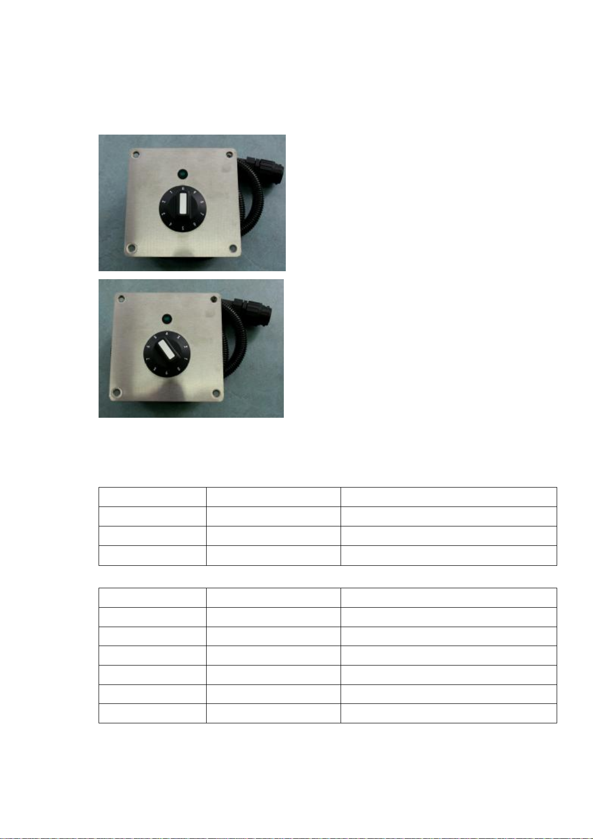
3.8 Installationoperatingunit.......................................................................................12
3.9 Electricalinstallation..............................................................................................13
4Operatingtest............................................................................................................14
5Operation...................................................................................................................15
5.1 Cookingprocess.....................................................................................................15
5.2 Comfort..................................................................................................................15
6Safetyinstructions.....................................................................................................16
6.1 Riskintheeventofnon-observanceofthesafetyinformation................................16
6.2 Safetyconsciouswork............................................................................................16
6.3 Safetyinformationfortheoperator/operatingpersonnel..........................................16
6.4 Unauthorizedreconstructionanduseofspareparts.................................................17
6.5 Improperoperatingmethods...................................................................................17
6.6 Pandetection..........................................................................................................17
6.7 Controloftheheatingarea......................................................................................17
7Outofoperation........................................................................................................18
8Faultfinding/Rectification........................................................................................19
8.1 Malfunctionwitherrorcode...................................................................................19
8.2 Malfunctionwithouterrorcode..............................................................................20
9Cleaning.....................................................................................................................22
10 Support......................................................................................................................23
11 Wastedisposalconcept.............................................................................................24

-2-
1Generalremarks
Theseinstructionsforusecontaininformationwhichisfundamentallyimportantandmustbe
takenintoaccountduringassembly,operationandmaintenance.Theymustthereforeberead
verycarefullybeforeinstallationandoperationbytheresponsiblespecialiststaffandthe
operator(s).Theymustalwaysbeavailableforconsultationattheplace ofoperation.
1.1 Descriptionofdanger signs
Thissymbolidentifiesthesafetyinformation
whichmaycausedanger(personalinjury)for
peopleatnon-observance ofproperoperation.
Thisdangerousvoltagewarning symbol
indicatesariskofelectricshockandhazards
fromdangerousvoltage.
CAUTION Indicatesahazardorunsafepracticewhich
couldresultinminorpersonalinjuryor
propertydamage.
Electromagneticfield
Toreduce theriskoffireorelectric
shock, do notremoveoropencover.
Nouserserviablepartsinside.
Referservicing toqualifiedpersonnel.
Informationsignsmounteddirectlyonthecookermustbeobservedatalltimesandkeptina
fullylegiblecondition.
Warning
Riskoffireorelectricshock
Donotopen

-3-
1.2 Purposeofinductioncookers
Theinductioncookers„Install-Line“areespeciallysuitableasbuilt-incookersinclosed
countersforthepreparationofmeals.Thecookerscanbeusedforcooking,keepingwarm,
flambéing,roasting,etc.offood.Thecookingorfinishing process withthese„Install-Line“
inductionappliancesmustonlybecarriedoutwithrecommendedtypesandsizesofpans.Do
notuseNO NAME panmaterialbutonlypansappropriateforinductioncooking!

-4-
2Descriptionofproducts
2.1 Scopeofsupply
•Generatorwithbuilt-inframeincluding glasstop
•Operatingunit
2.2 Products
Wedisposeseveralbasictypeswithdifferentperformancesandmeasurements.Builtina
robustmethodofconstruction,theyarecompactandpowerfulwitharevolutionary
technologyinacompletecaseofCrNi-steel.Equippedwithcontinuoscontrol,theyallow
efficientcooking.
•Simpleoperationwithrotaryswitchwithintegratedmainsswitch
•Compactmoduleinaframedesignwithaninductiongenerator,controller,coil,ventilator,
glass ceramiccookingzonewithpowerrotaryknobandLED-indicatorfixedonaCNS
plate.
•Electroniclimitationoftheconnectedload
•Compactpowerfulelectronicsenabletightconstructionandsafeoperation
•Amaximumofsafetythankstomultiplefunctionsofprotectionandchecking
•Shortcookingtime
•Compactmeasurement–lightweight
•Fulfillsthelateststandards:VDE EN60335-1;-2/36;CE-conforming
UL197;CAN/CSA/C22.2No.109

-5-
2.3 Install-units ataglance
Beforecarrying outfunctionchecks, theoperatormustknowhowtooperatethecooker.
ModelSH/IN
ModelSH/WO/IN

-6-
Controlknob
Thenumberthatpointstotheindicatoroperationmarkstheactualpositionofthecontrol
knob.
2.4 Technicalspecifications
Dimensions Dimensionglass ceramicMeasurementofmountingconstruction
BH/IN 260 x260mm 310 x310mm
SH/IN 320 x320mm 384 x384mm
SH/WO/IN ∅300mm 384 x384 mm
Electrical Voltage Power
BH/IN2500 208 /230/240 2,5kW
SH/IN3500 208 /230/240 3,5kW
SH/IN5000 208 /230/400/440 5,0kW
SH/WO/IN3500 208 /230/240 3,5kW
SH/WO/IN5000 208 /230/400/440 5,0kW
SH/WO/IN8000 400 /440 8,0kW
OFF-position:
0pointstotheindicationoperation
ON-position:
Anypositionwherenot0points totheindicatior
operation.

-7-
Operatingconditions
Max. tolerance ofsupplyvoltage +6/-10 %
Supplyfrequency 50/60 Hz
Protectionclass IPX0
Minimaldiameterofthepan(BH/INandSH/IN) 12 cm
Max. ambienttemperature Storage -20°-+70°C
Function +5°-+40°C
Max. relativehumidityofair Storage 10%-90%
Function 30%-90%

-8-
3Installation
3.1 Scopeofdelivery
Thegeneratorisdeliveredwithfirmlyfixedbuilt-inframeincludingglasstopandseparate
operatingunit.
CAUTION Pleasenotethattheunitisnotcompletely
assembled. Payattentiontotherequirements
ofinstallation.
3.2 Requirementsofinstallation
Theinductionappliance hastobebuiltinacleanand evensurface (table,counter,stove)at
hisdefiniteplace.
Makeattentionthattherequirementslistedinthischapterarefulfilled.
Install-Lineappliancesmustonlybefixedinclosedcounters.
Therearsideoftheinductionunitbelowthefanhastobeabsolutelyfree regardingdangerof
obstructionandairintake.Anoptimalairintakemustnotbereducedbytheinstallation.If
necessary,aperfectairsupplyhastobeguaranteedbyadding aflexibleairductincluding a
shackle(availableasaccessory). Makespecialattentiontotheairinletandairoutletopenings:
therehastobeadistance ofatleast30 mmbetweenobstructionslikewallsorfloors. In
additiontothatmakeattentionthattheairofairinletandairoutletdo notmix.We
recommendtoguarantee asupplyoffreshairbyfixing anairductincl.shackleorbyair
openings. Theairexitmustnottobehinderedbyanyobstructions.
3.3 Definitionofinterfaces
Pleaseobservethefollowing rules:
•Checkandensurethatthesupplyvoltageandthelinecurrentmatchesthespecifications
givenontheratingplate
•Thisinductionappliance isequippedwithmainscableandplug whichcanbeconnectedto
thesocket.Theconnectormustbeeasilyaccessibletodisconnecttheunitfromthenet.
•Whenresidualcurrentcircuitbreakersareused,theymustberatedforabreakingcurrent
of30mAormore.
•Thisinductionunitisequippedwithaninternalaircooling system.Makesurethattheair
supplyandairexhaustarenotblocked(wall,fabricetc.).

-9-
•Makesurethattheinductionunitdoesnottakeinhotambientair(concernsunitsstanding
sidebyside,oronebehind theother,orstandingnearafrying panoranoven),otherwise
anairductincl. shacklehastobeadded.
•Theinductionunitmustnotbeplacednexttoanovenoranotherheatproducingunit.
•Theairintaketemperaturemustbeunder40°C
•Theoperatingstaffhastomakesurethatinstallation,supportandinspectionisdoneby
qualifiedpersonnel.
3.4 InstallationclippingBH/IN2500
Makesurethatthesize oftheclipping inthebuilt-inzoneis290 x290 mm,thedepthofthe
clipping 200 mmandthebaseatleast340 x273mm.
310
3
1
0
260
260
min.290 x 290
min. 200
airsupply
Mounting height
Therequirement cut-outoftheworktop
280
ventilator
airsupply
airexit airexit
Netzkabel
171
1
0
3
1
,
5
Ceran-surface
1
8
6
Frontview
connection clutch
for operation device
plug-inclutch
foroperation device
280
84
1
2
8

-10-
3.5 InstallationclippingSH/IN3500 and SH/IN5000
Makesurethatthesize oftheclipping inthebuilt-inzoneis350 x350 mm, thedepthofthe
clipping 240 mmandthebaseatleast410 x353 mm.
min. 350 x350
min. 240
Airsupply
Mounting height
Therequirement cut-out ofthe worktop
Airsupply
330
183
143
1,5
Side viewoftheright
384
3
8
4
320
320
Ceran -surface
331
98
Plugtypeconnection
foroperatingdevice
Plug-infor
operatingdevice
Netcable
Front view
2
2
6
1
8
1

-11-
3.6 InstallationclippingSH/WO/IN3500, SH/WO/IN5000 and
SH/WO/IN8000
Makesurethatthesize oftheclipping inthebuilt-inzoneis365 x365 mm,thedepthofthe
clipping 300 mmandthebaseatleast410 x353 mm.
min.368x368
min. 300
Airsupply
Mounting height
Therequirementcut-out ofthe work top
384
3
8
4
Ø300
WOK-CERAN-BOWL
330
183
214
1,5
Sideviewof the right
Air supply
Ventilator
Air exit Air exit
331
297
98
Plug-inclutch
foroperationdevice
Connectionclutch
foroperationdevice
Netcablel
Front view
363,5
2
5
2
3.7 Advice forinstallation
Assoonasthemountingdevicesaccordingtotheabovementionedstepsarefinished,you
maycontinuewithinstallation.Putthecompletelypre-fixedinductionunitintotheclipping.
Stickthemountingconstructionontheworkingarea bymeansofsilicon.

-12-
3.8 Installationoperatingunit
Thisunitissuppliedcompletelywithanoperatingunit. Inordertofixthisonacover, takethe
clipping forthepowerswitchandtheLEDintoaccount.Theoperatorcontrolpanelhastobe
fixedverticallyontheinstallationpanel.ThecableforthepowerswitchandtheLEDhavea
lengthof100 cm.
104
120
120
1
0
4
57
9
3
2
0
14
19
44
106
120
93
2x ø5
120
60
28
4x countersunk
ø8 x ø4,5
104
8
120
38
50,5
104
8
ø8,5
ø10,2
4x R5

-13-
3.9 Electricalinstallation
CAUTION Ifthevoltageiswrong,thecookercanbe
damaged.
Theinstallationoftheelectricitymustbefittedbyapprovedinstallationcontractorsin
accordance withspecificnationalandlocalinstallationinconformitywithall safety
regulations. Thewarning signsandratingplatesontheappliancesmuststrictlybefollowed.
Checkandensurethatthesupplyvoltageandthelinecurrentmatchesthespecificationsgiven
ontheratingplate.
Max. tolerance ofsupplyvoltage +6/-10 %
Supplyfrequency 50/60 Hz
•Turncontrolknobtooffposition(„0“)
•Connectoperatingunittothegenerator
•Connecttheunittothepowersocket
(Theunitisdeliveredcompletelywithmainscableandplug.)
Theinstallationisnowfinishedandanoperatingtestmustbedoneaccordingtochapter4.

-14-
4Operatingtest
Removeall objectsfromtheglassceramiczone,verifythatthisarea isneithercrackednor
broken.Donotcontinuetheusewhentheglass ceramiccookingzoneiscrackedorbroken,
immediatelyswitchitoffanddisconnectthecookerfromthepoweroutlet.
CAUTION Theglass ceramiccookingzoneiswarmedup
fromtheheatofthepan. Toavoidinjuries
(burning)donottouchthisarea.
Useapansuitableforinductioncooking,having abottomdiameterofatleast12 cm(only
BH/INandSH/IN).
•Putsomewaterinthepanandplace itinthecenteroftheheatingarea.
•TurnthecontrolknobtoanON position.Theindicatorwilllightup (green)andthewater
willbeheated.
•Takethepanawayfromtheheatingarea, theindicatorlightwill flash.
•Place thepanbackontheheatingarea,theindicatorwill lightandtheheatingprocess will
continue.
•TurnthecontrolknobintheOFF-position,theheatingprocess willstop,indicatorlight
turns out.
Theshining indicatorlightoperationmeansthatenergyisbeing transferredtothepan.
Iftheindicatoroperationremainsoff, checkthefollowing:
•Is thecookerconnectedtothepoweroutlet?
•Is thecontrolknobinON positon?
•Doyouuseasuitblepan(bottomdiameteratleast12 cm(onlyBH/INandSH/IN),pan
madeofsuitablematerial)?
•Is thepanplacedinthecenteroftheheatingarea?
Toverify,ifthepanissuitable,useapermanentmagnetandfind outifitstickstothebottom
ofthepan.Ifnot,yourpanisnotsuitableforinductioncooking.Chooseapanwhichis
recommendedforinductioncooking.
Ifinspiteofall positivecontrolsandtests, thecookerdoesn’twork,refertotheFaultFinding
Section.

-15-
5Operation
5.1 Cookingprocess
Theinductioncookerisswitchedonbyturning thecontrolknob(OFF þON)anditis
immediatelyreadyforoperation.Theluminousindicatoroperationlightmeansthatenergyis
being transferredtothepan.Thepowerratingissetbyturningthecontrolknob.The
inductivepowerdependsonthepositionofthepotentiometer:
⇒position1> 1minimumpower
⇒position9> 9maximumpower(onlyBH/IN)
⇒position12 > 12 maximumpower
Duetothefollowing characteristics,theoperatormustbemoreattentivewhenusing the
inductioncookerthanitwouldberequiredwithotherappliances:
Theheatstoragecapacityofthissystemisverylow.Iftheheatinglevelischangedbyturning
thecontrolknob,thefoodisimmediatelyexposedtoadifferenttemperature.Donotput
emptypansonthecookingzone,putfirstgreaseorliquidintothepanandstartthecooking
process afterwards.Emptypansandpotsheatupveryquickly.Adjusttheheatinglevel
carefullytotherequiredcookingmode.Setandadjustthepowerbyturningthecontrolknob.
Thepanshouldalwaysremaininthecenteroftheheatingarea,otherwise,thebottomofthe
panisheatedup unequallyandthefoodinsidethepanmayburn.Whenheatingup oil or
grease, constantlycheckthepantopreventoilandgreasefromoverheatingandburning.
5.2 Comfort
Thecookertransmitsenergyonlywhenapanisplacedontheheatingarea,independentlyof
thepositionofthecontrolknob.Ifyoutakethepanawayfromtheheatingarea,power
transfertothepanstopsimmediately.Ifthepanisputbackontheheatingarea,theselected
powerwillbetransferredtothepanagain.
Afterswitching thecookertotheoffpositionthecookingprocess willstop.Exceptofthepan,
noheatisstored.

-16-
6Safetyinstructions
6.1 Riskintheeventofnon-observance ofthesafetyinformation
Dangerforpersons,fortheenvironmentandforthecookeraswellasclaimsfordamagesof
anykind canresultofnon-observance ofthesafetyinformation.Certainrisksmaybe
associatedwithnon-observance ofprecautions,including:
•Dangertopersonsthroughelectricalcauses
•Dangertopersonsthroughoverheatedpans
•Dangertopersonsthroughanoverheatedcookingplatform(ceranglass)
6.2 Safetyconscious work
Thesafetyinformationpointedoutintheseinstructionsforuse,theexistingnational
regulationforthepreventionofaccidentsaswellasanyinternalworking,operatingand
safetyregulationstipulatedbytheoperatormustbeobservedatanytime.
6.3 Safetyinformationfortheoperator/operatingpersonnel
Anyrisksfromelectricpowermustbeeliminated.Thecookinginductionunitshall onlybe
usediftheinstallationoftheelectricityisfittedbyanapprovedinstallationcontractorin
accordance withspecificnationalandlocalregulations.
•Theheatingarea iswarmedup fromtheheatofthepan.Toavoidinjuries(burning)do not
touchtheheatingarea.
•Toavoidoverheatingofpansbyevaporateofthecontent,don’theatup pansunattended.
•Switchthecontrolknoboffifyoutakethepanawayforawhile.Thiswillavoidthe
heatingprocess tocontinueautomaticallywhenapanisplacedbackontheheatingarea.
So,ifanypersonstartstousethecooker,he/shewillhavetostarttheheatingprocess by
turningthecontrolknobintheON-position.
•Donotinsertanypieceofpaper,cardboard,cloth,etc.betweenthepanandtheheating
area, as thismightinitiateafire.
•Asmetallicobjectsareheatedup veryquicklywhenplacedontheheatingarea,donot
place anyotherobjects(closedcans,aluminiumfoil,cutlery,jewelry,watchesetc.)onthe
inductioncooker.Personswithapacemakershouldconsulttheirdoctorwhethertheyare
safenearaninductioncooker.
•Aluminiumfoil andplasticvesselsmustnotbeplacedonthehotsurface.
•Thesurfacemustnotbeusedforstorage.
•Donotplace creditcards,phonecards,cassettetapes, orotherobjectssensitiveto
magnetismontheCeranglass.

-17-
•Theinductioncookerhasaninternalair-coolingsystem.Donotobstructtheairinlet-and
airoutlet-slotswithobjects(cloth). Thiswouldcauseoverheatingandthereforethecooker
wouldswitchoff.
•Avoidliquidenteringintothecooker.Donotletwaterorfoodoverflowthepan.Donot
cleanthecookerwithajetofwater.
•Iftheheatingarea (Ceranglass)iscrackedorbroken,theinductioncookermustbe
switchedoffanddisconnectedfromtheelectricconnection.Don’ttouchanypartsinside
thecooker.
•Ifthesupplycordisdamaged,itmustbereplacedbythemanufacturer, theservice agentor
asimilarlyqualifiedpersoninordertoavoidahazard.
6.4 Unauthorizedreconstructionanduseofspare parts
Reconstructionofthecookerorchangestothecookerarenotallowed.Contactthe
manufacturerifyouintendtomakeanychangesonthecooker.Toguarantee safety,justuse
genuinesparepartsandaccessoriesauthorizedbythemanufacturer.Theuseofother
componentswillvoidallwarranty.
6.5 Improper operatingmethods
Theoperatingreliabilityofthecookerscanonlybeguaranteedbycarefuluse.
6.6 Pandetection
Panshaving adiameterlessthan12 cmarenotdetected(onlyBH/INandSH/IN).Duringpan
detection,theindicatoroperationflashes.Nopoweristransferredandtheindicatorlamp
flashesifnopanoranunsuitablepanisdetected.
6.7 Controloftheheatingarea
Theheatingarea iscontrolledbyatemperaturesensor.Overheatedpans(hotoil,emptypans)
canbedetected.Energytransferwillbestopped. Theinductionunitmustbere-startedafterit
hascooleddown.

-18-
7Out ofoperation
IfthecookerisoutofoperationmakesurethatthecontrolknobisintheOFFposition.Ifyou
don’tusethecookerforalongperiod(severaldays), unplug theunit. Makesurethatnoliquid
canenterintothecooker,donotcleanthecookerwithajetofwater.

-19-
8Faultfinding/Rectification
Thecookersmayonlybeopenedbyauthorizedservice personnel.
CAUTION Donotopenthecooker,dangerouselectric
voltageinside.
Stopanyactionsiftheheatingarea (Ceranglass)iscrackedorbroken.Theinductioncooker
mustbeswitchedoffanddisconnectedfromtheelectricsupply.Don’ttouchanypartsinside
thecooker.
8.1 Malfunctionwitherrorcode
Numberofflashing
signals(Code) Possiblecause Actiontotakebyoperatoror
operatingpersonnel
E03
-...-...
Overheatedheatsink Letunitcooldown
Checkairfilterandairflow
Air-cooling systemobstructed Verifythatairinletandairoutlet
arenotobstructedwithobjects
Cleanairfilter
E04
-....-....
Overhatedcookingzone Letunitcooldown
Checkairfilterandairflow
E06
-......-......
Overheatedelectronic Letunitcooldown
Checkairfilterandairflow
Ambienttemperaturetoo high
(thecooling systemisnotableto
keepthecookerinnormal
operatingconditions 2))
Verifythatnohotairissuckedin
bythefan.
Reduce theambienttemperature.
Theairinlettemperaturemustbe
lowerthan40ºC/110ºF.
E07
-.......-.......
Emptycookingsensing element
activated Resetemptycookingprotection
byswitching theunitoff
Ambienttemperaturebeyond
operatingrange Makesurethattheoperating
conditions(especiallythe
ambienttemperature)arekept
E08
-........-........
Erroronsensingelement Contactserviceagent
Orderoferrormessage:Theindicatorlamplightsup foranintervalof0,6sec.Thenumberof
thefollowing shortflasheshastobecountedandinformsaboutthekindoferror
correspondingtotheabovementionedcodesystem.
Thecodewillrepeatuntiltheerroriscancelled.
This manual suits for next models
5
Table of contents
Other Metos Cooker manuals
Popular Cooker manuals by other brands

DS Produkte
DS Produkte CK-S93120 instruction manual

Baumatic
Baumatic PROFESSIONAL Series instruction manual

Indesit
Indesit IT50C1 operating instructions

Fisher & Paykel
Fisher & Paykel OR30SDPWIX Installation instructions and user guide

Electrolux
Electrolux EVE611SA user manual

Euromaid
Euromaid EG90S user manual