metran MK3075 Service manual

METRAN
MULTI-FUNCTION
AIR TO WATER HEAT PUMP
MULTI-FUNCTION
AIR TO WATER HEAT PUMP
Installation & instruction manual
CODE:MK3075/MK3076/MK3071

Multi-Function Heat Pump
Contents
I. Introduction
II. Specification
III. Installation
IV. Function diagram of the remote controller
V. Maintenance and repair
VI. Wiring diagram
VII. Engineering installation diagram
-------------------------------------------------------------------------------------
1.User Guide------------------------------------------------------------------------------------
2.Special warning------------------------------------------------------------------------------
3.Note---------------------------------------------------------------------------------------------
4.Work principle and function introduction-----------------------------------------------
----------------------------------------------------------------------------------
---------------------------------------------------------------------------
--------------------------------------------------------------
3.Product appearance and installation dimension--------------------------------------
------------------------------------------------------------------------------------
1.Outdoor unit installation position---------------------------------------------------------
2.Outdoor unit installation ----------------------------------------------------------
3.Installation options--------------------------------------------------------------------------
4.Install location select------------------------------------------------------------------------
5.The unit and water tank installation------------------------------------------------------
6 -----------------------------------------------------------
.Terminal equipments pipe connection--------------------------------------------------
8.Installation of the temp detector----------------------------------------------------------
9.Electrical wiring------------------------------------------------------------------------------
10. Electrical Wire selection------------------------------------------------------------------
11.Trial run----------------------------------------------------------------------------------------
------------------------------------------
1.Remote controller interface displays ---------------------------------------------------
----------------------------------------------------------------------
-------------------------------------------------------
-----------------------------------------------------------------
-----------------------------------------------------------
---------------------------------------------------
---------------------------------------------------------------------------
------------------------------
9.Parameter Table-----------------------------------------------------------------------------
-------------------------------------------------------------------
1.Care and maintenance---------------------------------------------------------------------
2.Malfunction Indicating Table.-------------------------------------------------------------
3.Determine and solve malfunction--------------------------------------------------------
-----------------------------------------------------------------------------
1.Double system type electrical box of internal structure----------------------------
2.MK3071 PCB Power sequence, current protection board-------------------------
3. MK3075 PCB input and output port definition----------------------------------------
4. Wiring diagram------------------------------------------------------------------------------
----------------------------------------------------
1.System application connection diagram-----------------------------------------------
2.System application connection diagram-----------------------------------------------
3. Auxiliary heat source connection--------------------------------------------------------
-------------------------------------------------------------
1.Type naming rules
2. onolithic
Notice
.Terminal equipment installation
7
2.Operation and display
3.System State parameter checking
4.System parameter setting
5.The maintenance time inquires
6.Date/ time/ timing on and off settings
7.Fault code display
8.Lock button/ Fahrenheit and Celsius change
4.Remote controller connection
M type performance
1
1
1
1
2
3
3
3
6
8
8
8
9
9
9
10
10
11
11
12
14
15
15
15
17
18
20
20
20
21
21
22
22
23
24
25
25
25
26
27
28
28
29
30
31

1
Multi-Function Heat Pump
I. Introduction
1.1.This manual contains the necessary information of correct installation, commissioning, use
and maintenance of machinery.
1.2.In order to use this product better and more safety, please read this instruction carefully before
install and use, and focus on the installation, use and maintenance of all considerations, taking
into safekeeping for when required.
1.3.Heat pump is a highly specialized appliances, improper installation may cause damage or
danger, so the corresponding installation and maintenance need professionals, users please
contact our company special, commissioned local installation repair services department,
carefully read the installation section, and follow the prompts to install.
1. User Guide
2. Special warning
2.1.Please ask a qualified professional installation company responsible for installing heat
pumps. Installation people should have relevant professional knowledge, when self-
installation, the wrong action will result in fire, electric shock, injury, leakage, and so on.
2.2.When installation, please check the distribution power capacity, switches, sockets whether
according to our heat pump power supply requirements, details please refer to unit nameplate
or technical data sheet on the installation instructions.
2.3.When power connect, the unit must be a reliable ground connection, confirm that the ground
wire is effective. If the ground is imperfect, may result in personal injury.
2.4.Heat pump before testing, hot water side and air-conditioning side of the water system must
be full of water, drain pipes before switch on, test the hot water side and air-conditoning side
water system water pump independently, when normal, turn off the water pump exit test
status, allowed to select the operating mode into the normal state of the unit test run.
2.5.The water above 52 may cause skin burns, tank hot water need mixed with cold water
before use.
2.6.Insert any tool within the heat pump is strictly prohibited, in order not to hit the fan result in unit
damaged or an accident.
2.7.When installation, be sure to install filter in the heat pump inlet, make sure unit inlet water was
clean enough.
2.8.The units have been set parameters well in the factory, non-professionals against
arbitrary adjustments.
2.9.When the unit needs to be moved or re-installation, Please ask a qualified professional
installation company for help.
2.10.Any self-modification or repair is forbidden, if repair not properly, may result in fire, electric
shock, injury and leakage incidents, you should ask agent or professional to repair.
3.Note
3.1.Please confirm that the drainage pipe is smooth outlet, improper piping installation will result
in water leakage, or wet the furniture.
3.2.Confirm whether already install the leakage protection switch, or else may result in electric
shock.
3.3.Prohibiting installed in the position of combustible gas leaks.
3.4.Ensure the installation base, lifting is solid and reliable enough.

Multi-Function Heat Pump
3.5.Please correct connect the cable, if the cable connection error, it may damage the electrical
components.
3.6.Before installation, you should not expose the unit in water or other moisture, it may cause
short-circuit the electrical components.
3.7 If unit in the room leaks refrigerant in the installation process, then please immediately open the
room ventilation.
3.8.The unit heat exchanger air inlet and outlet position can not be any things obstruction in and
out of wind.
3.9.The unit wire controller must be fixed at a convenient operation, dry environment, not to
rain water and the out of children , do not install in the bathroom, so as not to affect the
unit work by wet.
3.10.When the installation is completed, confirm that there is no leakage of refrigerant.
reach
4. Work principle and function introduction
Units under the reverse Carnot cycle principle, take a small amount of electricity as driving force
and refrigerant as carrier, an endless absorption the air and water low-grade thermal energy which
is difficult to use(-15-43 ), change into available high-grade heat, achieve low temperature heat
transfer to high temperature heat; then high-grade heat energy released into the water system to
supply domestic hot water (up to 60 ), through the hot water supply pipeline transport to users to
meet the demand for domestic hot water and heating.At the same time, It also can produce more
than 7 water through the pipes transport to user terminal equipment to meet the cooling
needs.Users can choose the heat pump operating mode and temperature settings, select: cooling,
heating, hot water, cooling + hot water supply, heating + hot water supply. Mode selection and
temperature set finish, start the unit, enter into automatic operation.
The highest COP up to 7.5 or more when heat pump running.
2
Compressor
Appliance
side
Appliance
side
Cold/hot
water tank
heat exchange heat exchange
Air heat exchange
hot water
tank
expansion valve

Multi-Function Air To Water Heat Pump
2. M type performanceonolithic
2.1.Horizontal fan direction type
Note:(1)Cooling:Outdoor air trmp:35 /24 ,Outlet water temp:7 ,Inlet water temp:12 ,Heating:Outdoor air temp:7 /6 ,Outlet water temp:45 ,
Input water temp:40 .
(2)Using in ambient temperature: -15 ~45 .
Model
Rated Output Water
Rated Input Power
Rated Input Current
M
Power Supply
Compressor
Compressor Qty
Fan Qty
Noise
Water Connection
Water Flow Volume
Water Connection
Water Flow Volume
Refrigerant Gas Type
Main Unit Net Dimensions(L/M/H
Main Unit Shipping Dimensions L/M/H
Net Weight
Shipping Weight
inmum circuit ampacity
Max.fuse
MACHRW
L/h
kW
BTU/h
kW
BTU/h
kW
A
A
A
V/PH/Hz
dB(A)
inch
m/h
inch
m/h
mm
mm
kg
kg
3
3
Rated Heating Capacity
Rated Cooling Capacity
The figure represents the horse power of unit
eg:010 means 1 horse power
A: Horizontal fan direction
B: Upward fan direction
Design alternative serial number
MA FP -***- A (**)
Energy exchange medium
A: Air
MW: Water
M
FP: Fan coil
1.2.Split outdoor unit type naming rules
II. Specification
1. Type naming rules
MA CHR W - *** - Z A / P S (**)
Source medium
MA: Air source
MW: Ground source
Function of the unit
C: Cooling
R: Heating
CH: Cooling and hot water
CR: cooling and heating
CHR: C heating and hot waterooling
Energy exchange medium
A: Air
W: Water
Z: Integrated type
W: Split type(indoor unit )
P: With built in pump,
(without built in pump )omitted
S: 3phase(single phase )omitted
A: Horizontal fan direction
B: Upward fan direction
Design alternative serial number
The figure represents the horse power of unit
eg:010 means 1 horse power
1.1.All in one unit type naming rules, Split indoor unit type naming rules
Hot water side
Air condition side
R410A
030ZA/(P)
205
7.5
25600
9.0
30800
2.70
12.3
20
30
220/1/50
Rotary
1
1
55
1
2-3
1
3-4
1115/470/945
1205/525/975
112
132
035ZA/(P)
230
9.0
30800
10.5
35900
3.10
14.1
20
35
220/1/50
Rotary
1
1
55
1
2-3
1
3-4
1115/470/945
1205/525/975
115
135
040ZA/(P)
270
10.0
34200
12.0
41000
3.60
16.4
25
40
220/1/50
Scroll
1
1
55
1
4-5
1
3-4
1115/470/945
1205/525/975
125
145
050ZA/(P)S
380
12.5
42700
15.0
51200
4.50
7.9
15
20
380/3/50
Scroll
1
2
57
1
4-5
1
3-4
1115/470/1250
1205/525/1280
150
170
040ZA/(P)S
270
10.0
34200
12.0
41000
3.60
6.3
10
15
380/3/50
Scroll
1
1
55
1
4-5
1
3-4
1115/470/945
1205/525/975
125
145
045ZA/(P)S
355
11.5
39300
13.5
46100
4.00
7.0
10
20
380/3/50
Scroll
1
1
55
1
4-5
1
3-4
1115/470/945
1205/525/975
135
155
060ZA/(P)S
445
15.0
51200
18.0
61500
5.30
9.3
15
25
380/3/50
Scroll
1
2
57
1
5-6
1
4-5
1115/470/1250
1205/525/1280
155
175
3

Multi-Function Air To Water Heat Pump
2.2.Upward fan direction type
Rated Heating Capacity
Rated Cooling Capacity
Hot water side
Air condition side
Model
Rated Output Water
Rated Input Power
Rated Input Current
Minmum circuit ampacity
Max.fuse
Power Supply
Compressor
Compressor Qty
Fan Qty
Noise
Water Connection
Water Flow Volume
Water Connection
Water Flow Volume
Refrigerant Gas Type
Main Unit Net Dimensions(L/M/H
Main Unit Shipping Dimensions L/M/H
Net Weight
Shipping Weight
MACHRW
L/h
kW
BTU/h
kW
BTU/h
kW
A
A
A
V/PH/Hz
dB(A)
inch
m/h
inch
m/h
mm
mm
kg
kg
3
3
R410A
300ZB/(P)S
2030
75.0
255900
90.0
307100
26.50
46.5
65
110
380/3/50
Scroll
4
3
62
2
20-25
3
15-20
2180/1070/2000
2500/1270/2200
1100
1160
250ZB/(P)S
1760
62.5
213300
75.0
255900
22.10
38.8
55
90
380/3/50
Scroll
4
3
62
2
13-15
3
15-20
2180/1070/2000
2500/1270/2200
950
1010
200ZB/(P)S
1320
50.0
170600
60.0
204800
17.70
31.1
45
75
380/3/50
Scroll
3
3
62
2
13-15
2
10-12
2180/1070/2000
2500/1270/2200
850
910
120ZB/(P)S
885
30.0
102400
36.0
122900
10.60
18.6
25
45
380/3/50
Scroll
2
2
58
1-1/4
7-8
1-1/4
6-7
1450/730/1260
1545/780/1310
300
325
100ZB/(P)S
755
25.0
85300
30.0
102400
8.90
15.6
25
40
380/3/50
Scroll
2
2
58
1-1/4
7-8
1-1/4
6-7
1450/730/1260
1545/780/1310
265
290
Rated Heating Capacity
Rated Cooling Capacity
Hot water side
Air condition side
Model
Rated Output Water
Rated Input Power
Rated Input Current
Minmum circuit ampacity
Max.fuse
Power Supply
Compressor
Compressor Qty
Fan Qty
Noise
Water Connection
Water Flow Volume
Water Connection
Water Flow Volume
Refrigerant Gas Type
Main Unit Net Dimensions(L/M/H
Main Unit Shipping Dimensions L/M/H
Net Weight
Shipping Weight
MACHRW
L/h
kW
BTU/h
kW
BTU/h
kW
A
A
A
V/PH/Hz
dB(A)
inch
m/h
inch
m/h
mm
mm
kg
kg
3
3
R410A
030ZB/(P)
205
7.5
25600
9.0
30800
2.70
12.3
20
30
220/1/50
Rotary
1
1
55
1
2-3
1
2-3
760/704/770
785/770/870
93
108
040ZB/(P)S
270
10.0
34200
12.0
41000
3.60
6.3
10
15
380/3/50
Scroll
1
1
55
1
4-5
1
3-4
860/806/970
890/870/1070
108
123
050ZB/(P)S
380
12.5
42700
15.0
51200
4.50
7.9
15
20
380/3/50
Scroll
1
1
55
1
4-5
1
3-4
860/806/970
890/870/1070
135
150
080ZB/(P)S
540
20.0
68300
24.0
81900
7.10
12.5
20
30
380/3/50
Scroll
2
2
58
1-1/4
7-8
1-1/4
6-7
1450/730/1060
1545/780/1110
250
275
060ZB/(P)S
445
15.0
51200
18.0
61500
5.30
9.3
15
25
380/3/50
Scroll
1
1
55
1
5-6
1
4-5
860/806/970
890/870/1070
150
165
Note:(1)Cooling:Outdoor air trmp:35 /24 ,Outlet water temp:7 ,Inlet water temp:12 ,Heating:Outdoor air temp:7 /6 ,Outlet water temp:45 ,
Input water temp:40 .
(2)Using in ambient temperature: -15 ~45 .
4

Multi-Function Air To Water Heat Pump
2.3.Split type performance
Note:(1)Cooling:Outdoor air trmp:35 /24 ,Outlet water temp:7 ,Inlet water temp:12 ,Heating:Outdoor air temp:7 /6 ,Outlet water temp:45 ,
Input water temp:40 .
(2)Using in ambient temperature: -15 ~45 .
2.4.Pressure-bearing tank performance parameters
100
100
G1
0.7
470 1060
550/550/1150
25/30
MX
L
inch
Mpa
mm
mm
kg
150
150
G1
0.7
470 1500
550/550/1600
30/35
200
200
G1
0.7
520 1500
590/590/1600
35/40
250
250
G1
0.7
600 1320
635/635/1420
45/50
300
300
G1-1/4
0.7
600 1540
53/60
635/635/1660
400
400
0.7
700 1500
775/775/1620
65/75
G1-1/4
500
500
0.7
700 1800
775/775/1920
73/83
G1-1/4
R410A
Rated Heating Capacity
Rated Heating Capacity
MACHRW(S)
MAFP
MAFP
Indoor Unit Model
Outdoor Unit (Side Fan)Model
Outdoor Unit (Top Fan)Model
Rated Output Water
Rated Input Power
Rated Input Current
Minmum circuit ampacity
Max.fuse
Power Supply
Compressor
Compressor Qty
Fan Qty horizontal / vertical
Noise
Refrigerant Liquid Pipe
Refrigerant Gas Pipe
Water Connection
Water Flow Volume
Refrigerant Gas Type
Indoor Unit Net Dimensions(L/M/H
Indoor Unit Shipping Dimensions L/M/H
Out door (Side Fan)Unit Net Dimensions(L/M/H
Out door (Side Fan)Shipping Dimensions L/M/H
Out door (top Fan)Net Dimensions(L/M/H
Out door (top Fan) Shipping Dimensions L/M/H
Indoor Unit Net/Shipping Weight
Out door (Side Fan)Unit Net/Shipping Weight
Out door (Top Fan)Net/Shipping Weight
L/h
kW
BTU/h
kW
BTU/h
kW
A
A
A
V/PH/Hz
dB(A)
inch
inch
inch
m/h
mm
mm
mm
mm
mm
mm
kg
kg
kg
3
Hot water side / Air condition side
030W/(P)
030A
030B
205
7.5
25600
9.0
30800
2.70
12.3
20
30
220/1/50
Rotary
1
1/1
50
3/8
1/2
1
2-3
600/630/785
710/750/915
885/470/700
980/525/725
660/660/860
750/700/960
55/70
40/45
45/57
035W/(P)
035A
035B
230
9.0
30800
10.5
35900
3.10
14.1
20
35
220/1/50
Rotary
1
1/1
50
3/8
1/2
1
2-3
600/630/785
710/750/915
885/470/700
980/525/725
660/660/860
750/700/960
58/73
40/45
45/57
040W/(P)
040A
040B
270
10.0
34200
12.0
41000
3.60
16.4
25
40
220/1/50
Scroll
1
1/1
54
1/2
5/8
1
3-4
600/630/785
710/750/915
885/470/945
980/525/975
660/660/860
750/700/960
100/115
60/65
50/65
040W/(P)S
040A
040B
270
10.0
34200
12.0
41000
3.60
6.3
10
15
380/3/50
Scroll
1
1/1
54
1/2
5/8
1
3-4
600/630/785
710/750/915
885/470/945
980/525/975
660/660/860
750/700/960
100/115
60/65
50/65
045W/(P)S
045A
045B
355
11.5
39300
13.5
46100
4.00
7.0
10
20
380/3/50
Scroll
1
1/1
54
1/2
5/8
1
3-4
600/630/785
710/750/915
885/470/945
980/525/975
660/660/860
750/700/960
105/120
60/65
50/65
050W/(P)S
050A
050B
380
12.5
42700
15.0
51200
4.50
7.9
15
20
380/3/50
Scroll
1
2/1
54
1/2
3/4
1
3-4
600/630/785
710/750/915
885/470/1250
980/525/1280
660/660/960
750/700/1060
110/125
70/75
60/75
060W/(P)S
060A
060B
445
15.0
51200
18.0
61500
5.30
9.3
15
25
380/3/50
Scroll
1
2/1
54
1/2
3/4
1
4-5
600/630/785
710/750/915
885/470/1250
980/525/1280
660/660/960
750/700/1060
115/130
70/75
60/75
20
20
G1
0.7
470 250
550/550/350
10/15
MH
L
inch
Mpa
mm
mm
kg
30
30
G1
0.7
470 380
550/550/480
12/17
50
50
G1
0.7
470 510
/22
550/550/610
15
80
80
0.7
G1-1/4
470 850
550/550/950
20/27
100
100
0.7
25/30
G1-1/4
470 1060
550/550/1150
120
120
0.7
28/33
G1-1/2
470 1300
550/550/1450
150
150
0.7
30/35
G1-1/2
470 1500
550/550/1600
Model
Water volume
WaterOutlet/Water Inlet
Max.Working Pressure Tank
Net Dimensions( xH
Shipping Dimensions L/M/H
Net/Shipping Weight
2.5.Buffer tank performance parameters
Model
Water volume
WaterOutlet/Water Inlet
Max.Working Pressure Tank
Net Dimensions( xH
Shipping Dimensions L/M/H
Net/Shipping Weight
5

Multi-Function Air To Water Heat Pump
2.6 Hot water tank and buffer tank options
1.1.If the unit without a tank when leave factory, please select tanks as follow requirements
(heater in the tank, if need the tank water temperature over 60 degrees, heaters required to
be installed, need not to install if not required).
1.2.This heat pump water heater can be equipped with tank-type water heater (Figure 1) and
closed-type water heater (Figure 2).
A. Select the tank-type water heaters:
1) The tank-type water heater should be able to withstand the rated pressure of 0.03MPa.
2) If the devices capacity more than 15L, and can not be empty by a outlet which install in the
pipe, it should be equipped with a kind of emission devices, which with tools to make it work.
(Emission devices can be combined with pressure relief devices)
3) The unit without water level control output, need external water tank level control equipment.
B. Select the closed water heaters:
1) If not installed pressure relief device inside the water tank, so must be fitted with pressure
relief devices (when installed refer to the "Third, installation, 3, pipe connection"), the
parameter value is 0.7MPa.
2) The water can drain from the pressure relief device in the
outlet pipe which should keep connected with the atmosphere.
3) The pressure relief device to periodically work to remove the
calcium carbonate deposition, and sure that device is not plugged.
4) Heat pump water heater installation is complete, the water
tank empty refer to the "three, installation, 5, trial run."
5) Design an enclosed heater which directly connect to water,
the rated pressure should be at least 0.6MPa.
6) If the devices capacity more than 15L, and can not be empty
by a outlet which install in the pipe, it should be equipped with
a kind of emission devices, which with tools to make it work.
(Emission devices can be combined with pressure relief devices)
Outlet
3. Product appearance and installation dimension
3.1.Installation dimensions of integrated type unit
450
820
806
970
A
B
C
D
Size
Units: mm
MACHRW
030ZB/(P)~035ZB/(P) 040ZB/(P)(S)~060ZB/(P)S
450
720
704
770
B
A
C
D
440
755
1115
1250
A
B
C
D
Size
Units: mm
MACHRW
440
755
1115
945
030ZA/(P) ~045ZA/(P)(S)
050ZA/(P)S~060ZA/(P)S
A
B
C
D
D
6
Inlet
Outlet Inlet
Figure 2
Figure 1
Outlet
Inlet
Tank
Ball valve Vent
Overflow
Water
level
Heaters

Size
Units: mm
MODEL
AB
MH20
MH30
MH50
MH80
MH100
MH120
MH150
470
470
470
470
470
470
470
250
380
510
850
1060
1300
1500
Size
Units: mm
MODEL
AB
MX100
MX150
MX200
MX250
MX300
MX400
MX500
470
470
520
600
600
700
700
1060
1500
1500
1320
1540
1500
1800
708
750
1450
1060
A
B
C
D
Size
080ZB/(P)S
Units: mm
MACHRW
100ZB/(P)S~120ZB/(P)S
708
750
1450
1260
D
B
C
A
A
C
B
2000
1070
2180
A
B
C
Size
Units: mm
MACHRW
200ZB/(P)S~300ZB/(P)S
Multi-Function Air To Water Heat Pump
4.2 Installation dimensions of split type unit
665
390
600
785
A
B
C
D
Size
030W/(P)(S)~060W/(P)S
Units: mm
MACHRW
D
C
A
B
440
525
885
945
A
B
C
D
Size
030A~035A
Units: mm
MAFP
440
525
885
1250
040A~045A 050A~060A
440
525
885
700
D
A
B
C
D
300
685
660
860
A
B
C
D
Size
Units: mm
300
685
660
960
A
B
C
D
MAFP
030B~045B 050B~060B
2.4. ressure-bearing tankInstallation dimensions of p
LR
LR
A
B
Temperature-
detection
Heating
cycle inlet 1
2.5. uffer tankInstallation dimensions of b
LR
LR
A
B
7
Heating
cycle outlet 1
Drain
Hot wate
cycle inlet
Hot wate
cycle outlet
Heating
cycle inlet 2
Heating
cycle outlet 2
Cold inlet
Cycle outlet 1
Temperature-
detection
Cycle inlet 1
Drain
Cycle outlet 2
Cycle inlet 2
Cold inlet

1. Outdoor unit installation position
2. Outdoor unit installation Notice
To avoid ventilation short, the outdoor unit discharged air should not return when installation.
Please keep enough space around the outdoor unit for repair. Right and wrong means as below:
2.1.To get enough air for ventilation of the unit, the installation position should be with good
ventilation.
2.2.The installation position can hold the outdoor unit without noise and shake.
2.3.No sunlight to the unit. Set an awning if necessary.
2.4.The water from rain and defrosting can be discharged in the installation position.
2.5.The unit will not be covered by snow in the installation position.
2.6.The discharged air will not face strong air in the installation position.
2.7.Be sure the noise caused by the unit ventilation and operation will not affect the neighbor.
2.8.The installation position will not be affected by garbage, oil and mist.
2.9.The outdoor unit will be damaged under the condition with oil, salt and sulfide air.
Wrong Right
MACON
III. Installation Notice
Multi-Function Air To Water Heat Pump
8

300mm
200mm
1500mm
600mm
Air outlet
500mm
200mm
600mm
Bolt
fix
500mm
200mm
600mm
700mm
400mm
600mm
1000mm
700mm
400mm
400mm
1000mm
2000mm
Multi-Function Air To Water Heat Pump
3. Installation options
3
A Side fan type installation space requirements:
.1. The unit can be installed in the balcony, roof, floor or any other convenient place and reliable
load-bearing.
3.2.Airiness place.
3.3.No heat radiation or other heat source place
3.4.Should be set up shed against the snow in winter.
3.5.Barrier-free at the air inlet or outlet place.
3.6.Outlet against strong winds blowing place.
3.7.There should be drainage channels around the machine in order to rule out the condensate.
3.8.Control Panel, do not install in the bathroom, so as not to affect the unit work by wet.
3.9. Should leave enough space around the machine. As shown below.
B Top fan type installation space requirements:
4.hot water tank(water tank)and buffer tank(water tank) install location select
4.1.The water tank can be installed in the outdoor with heat pump outdoor unit, such as balconies,
roofs, floors, also can be installed in the room.
4.2.Water tank must be standing install, the installation place is a solid foundation, must be bear
the weight of the tank when full of water.
4.3.Around the water tank , as well as water pipes and hot water pipes should install a valve.
4.4.Do not install the water tank, where exist pollute and corrosive gases.
5.The unit and water tank installation
5.1.Unit install base is concrete structures, also can be made of steel angle brackets, plus vibration
rubber pad placed on the ground or roof, to ensure the unit horizontally.
5.2.Installed base design should in accordance with units and water tanks installed size
And operational quality.
5.3.Directly use expansion bolts to fix unit and water tank to the concrete base.
5.4.Around the unit and tank should be drain or outlet.
9
Air intlet
Bolt
fix
Unit
Unit
Unit
Bolt
fix

Multi-Function Air To Water Heat Pump
6.Installation of terminal equipment
6.1.Indoor terminal equipment installation (such as: fan coil, radiator heater or floor heating), the
equipment should be installed in accordance with relevant regulatory requirements.
6.2.In accordance with the requirements of engineering design drawings, installation and
construction.
6.3.Use a soft connector to connect the unit and fan coil inlet and outlet pipes; install fan coil
condensate drain pipe, connect the condensate drain interface, and to ensure smooth drainage
of condensate water.
7. The unit and hot water tank, buffer tank and terminal equipments pipe connection
(Refer to installation diagram)
7.1.Pipe material selection, can be stainless steel pipe, copper pipe, aluminum water pipe, hot
water PPR pipes and so on, according with national health and safety standards, heat-
resistant, rust-proof, no scaling pipe.
7.2.The choice of pipe sizes can be used the one which is matches the heat pump inlet and outlet
main pipe, and, respectively connect to heat pump inlet and outlet, and follow the proper
construction of plumbing standards.
7.3.Water tank outlet pipe and overflow pipe installed in the gutter or outlet position as far as
possible, where convenient to drainage.
7.4.The unit and the junction to the tank must be installed valve or demolition loose joint, for
maintenance use.
7.5.Water pipes are arranged reasonably to minimize bending and reduce the pressure loss of
water system
7.6.The unit air-conditioning side and the hot water side circle inlet must be installed a above 50
mesh water filter to reduce the water system resistance loss.
7.7.The unit air-conditioning side and the hot water side which connect to running water must be
installed a one-way valve, filter and pressure relief devices (pressure relief devices used on
the closed water tank, water tank accessories in general, the parameter value 0.7MPa), in
accordance with the flow and valve arrow direction, to avoid flow be obstructed.
7.8.The unit hot water side circle outlet connect to tank circle inlet, and the host hot water side
circle inlet connect to tank circle outlet,tank hot water supply connect to hot water pipe.
7.9.Air-conditioning side buffer tank in series installed on the outlet of the main pipe.
7.10. After hot water side and air-conditioning side water system pipes, circulated pipes, hot water
supply pipes connected, it must be pipe connection rigorous testing , plus 0.7Mpa pressure
testing 24 hours, system pipes connector no leakage and clean and sewage pipes, to ensure
that the system clean, no debris. No leakage after the test, then pack the pipe and valve with
insulation (including the replenishment pipes and valves).
7.11.In order to discharge the water system air clean, avoid air trapping in the pipeline, the water
supply return pipe highest point should be set up a automatically exhaust valve.
7.12.The water system expansion tank, automatic water valve and stop valve should be installed
indoors, to prevent water pipes and valves crack when not use in the winter.
7.13.The metal pipe must be used above 50mm thickness of glass fiber or high-density fire
retardant PE for thermal insulation and moisture, PPR water pipe can be used 30mm
thickness of glass fiber or high-density fire retardant PE for thermal insulation and moisture to
prevent cold, heat loss and condensation.
10

Multi-Function Air To Water Heat Pump
7.14.The unit water inlet and outlet must install a thermometer, water pressure gage, to facilitate
inspection when operate.
1) Tubing pipeline should be separate test pressure, must not test with hot water unit or tanks.
2) The water system working pressure: 0.2-0 .7 Mpa.
3) The water system operating temperature: 5-75 .
4) Water can drain from the pressure relief device drainage pipe, and the piope keep open to
atmosphere.
5) The pressure relief device regularly move to remove the calcium carbonate, and prove that
the device is not plugged.
6) Installation of one-way valves, filters and pressure relief device, valve body arrow as same
as flow direction .
7) The pressure relief device discharge pipe should be installed in the frost-free environment in
A continuous down way.
Note:
9.Electrical wiring
9.1. should use dedicated power supply, power supply voltage line corresponding
with rated voltage.
9.2.The unit power cable must use copper cable, the cable diameter must ensure that
the unit's maximum starting current requirements.
9.3. power supply circuit must have a grounding wire, which should connect with
a reliable external ground wire, and the external ground wire is effective.
The unit
The unit
8. Installation of the temp detector
The head
of sensor
The heat
conduction
silica gel
Detector
Tank
The first step The second step The third step The fourth step
Tank Tank Tank
The heat
conduction
silica gel
Detector
The head
of sensor
< 5 pin
< 5 pin
The head
of sensor
Detector Detector
The head
of sensor
The heat
conduction
silica gel
< 5 pin
8.1.The first step Daub the heat conduction silica gel spreads in the front of sensor, and insert
into the detector.
8.2.The second step use < 5 pin to push the detector into the end of the detector against the
end of the sensor, and marks on level of the pin and the detector.
8.3.The third step putout the pin the position of mark to be at the same level with the inlet of
detector check whether the sensor is inserted to the pipe terminal.
8.4.The fourth step the inlet of the detector is sealed with the glass silica gel, and keep the inlet
of the detector upwards and uprightness about an hour
11

Multi-Function Air To Water Heat Pump
9.4.Wiring construction must be installed by professional technicians refer to circuit diagram.
9.5.Power lines and signal line layout should be neat, rational, strong and weak lines separate
and can not interfere with each other, while not contacted with the connecting pipe and the
valve body.
9.6.When power lines and control lines parallel, the wires were placed in each tube, also
leave appropriate distance between the lines.
9.7.Unit electric wire connection: take the unit power line, remote control three core lines,
electric heater power line, solar circulated water pump control power line, water tank
temperature sensing line, solar collector temperature sensor line, terminal equipments
connect to unit lines, through the unit wiring hole set into the electrical box, connect to the
appropriate terminals according to wiring diagram, and fix it by the pressure line of board in the
electrical box.
9.8.Unit control panel Code MK3075, Fuse specifications: 10A/250V
10. Electrical Wire Selection
10.1.Voltage drop occur may due to the large current draw during compressor starting, and may
be result in the compressor is difficult to stat. So we recommend selecting the wire
specification from the table below.
10.2.Size Table of Electrical Wire
within 5m
2.0
3.5
5.5
8.0
Within 10m
2.0
3.5
5.5
8.0
14.0
Within 15m
2.0
3.5
5.5
8.0
14.0
22.0
Within 20m
3.5
5.5
8.0
14.0
22.0
30.0
Within 30m
5.5
8.0
14.0
22.0
30.0
38.0
50.0
Within 50m
8.0
14.0
22.0
30.0
38.0
50.0
60.0
80.0
Within 1m
2.0
3.5
5.5
8.0
14.0
Starting current
(A)
Below 20
30
40
50
60
70
80
90
100
110
120
140
160
180
200
220
240
Below
Below
Below
Below
Below
Below
Below
Below
Below
Below
Below
Below
Below
Below
Below
Below
Markor Mark (Heat resistance temperature above 60 )
The wiring specifications (mm2)
Mark (Heat resistance
temperature above 120 )
Power supply
PCB
Unit
12
Compressor
COM
Power supply installation condition: The touching space of breaker should be more than 3mm,
use copper wire only.
12

Multi-Function Air To Water Heat Pump
10.3 Caution of Ground
The internal motor protector does not protect the compressor against all possible
conditions.Please be sure that the system utilizes the ground connection when installed in the
field.
10.4 Warning:
To avoid fire, electric shock and other accidents, keep in mind about these tips:
10.4.1.Only use power supply voltage indicated on the label, if you do not know the family of
voltage, contact the dealer or local power company.
10.4.2.When you use the unit by the maximum current please view the specifications, so make sure
your home's power supply (current, voltage and cable) to meet the machine's normal load
Requirements.
10.4.3.To protect the power lines. Power lines should be fixed, so that people will not be trip over or
the lines damaged by other things. Paying particular attention to plugs, which should be easily
plug into the socket, careful the plug position.
10.4.4.Do not overload wall plugs or extension the cable. Line overload can cause fire or electric
shock.
10.4.5.To ensure your safety, you must plug the power lines into the socket with a grounded
three-phase, and check to ensure your socket is accurate and reliable grounding.
030Z(W)A(B)
035Z(W)A(B)
040Z(W)A(B)
040Z(W)A(B)/S
045Z(W)A(B)/S
050Z(W)A(B)/S
060Z(W)A(B)/S
080ZB/S
100ZB/S
120ZB/S
200ZB/S
300ZB/S
220V/1PH/50Hz
2.5mm2
mm2
380V/3PH/50Hz
2.5mm2
mm2
4.0mm2
mm2
2.5mm2
mm22.5mm2
mm2
2.5mm2
mm22.5mm2
mm2
4.0mm2
mm22.5mm2
mm2
2.5mm2
mm22.5mm2
mm22.5mm2
mm2
2.5mm2
mm22.5mm2
mm22.5mm2
mm2
2.5mm2
mm22.5mm2
mm22.5mm2
mm2
2.5mm2
mm22.5mm2
mm22.5mm2
mm2
4.0mm2
mm24.0mm2
mm2
6.0mm2
mm24.0mm2
mm24.0mm2
mm2
6.0mm2
mm24.0mm2
mm24.0mm2
mm2
4.0mm2
mm24.0mm2
mm2
10.0mm2
mm2
4.0mm2
mm24.0mm2
mm2
16.0mm2
mm2
4.0mm2
mm2
0.5mm2
mm2
0.5mm2
mm2
0.5mm2
mm2
0.5mm2
mm2
0.5mm2
mm2
0.5mm2
mm2
0.5mm2
mm2
0.5mm2
mm2
0.5mm2
mm2
0.5mm2
mm2
0.5mm2
mm2
0.5mm2
mm2
0.5mm2
mm2
0.5mm2
mm2
0.5mm2
mm2
0.5mm2
mm2
0.5mm2
mm2
0.5mm2
mm2
0.5mm2
mm2
0.5mm2
mm2
0.5mm2
mm2
0.5mm2
mm2
0.5mm2
mm2
0.5mm2
mm2
15
15
15
15
15
15
15
15
15
15
15
15
50
50
50
50
50
50
50
50
50
50
50
50
RSTNLN
13
Host PowerMode Phase line Zero line Ground line Max.line
length (m) Signal line Tem. sensor
assistance line
Max.line
length (m)
Phase line
Zero line
Ground line
Phase line 1
Phase line 2
Phase line 3
Zero line
Ground line
Note:
1. used PVC insulated copper wire for above wiring
2. for installation requires, the line is longer than the maximum line length, please contact the
company
10.5.Power wiring as follows (single unit):
MACON

11.Trial run
11
Note:
.1.Check the hot water side, air-conditioning side and solar side of the water system piping and
all accessories are installed correctly, heat pumps, water tanks, terminal equipment piping
connections are correct. The fill water supply of hot water side, air-conditioning side and solar
side are normal, the replenishment port whether installed pressure relief valve, ony-way valve,
filter and other accessories.
11.2.Open the unit hot water side, air-conditioning and solar side hydrating valve, circular inlet and
outlet water valve, main pipe backwater valve, floor branch pipe valve, terminal
equipment inlet and outlet valve, fill the hot water side water tank, air-conditioning side
water tank and solar collector system with water. Check the valves should be open if all
open, the valves should be closed if all closed, pipe insulation if complete.
11.3.Open the exhaust valve, hot water valve, drain the pipe air, confirm pipe clean, close the
exhaust valve, hot water valve.
11.4.Check the power supply if required with the unit power supply on the nameplate, power supply
voltage if normal.
11.5.Check all power supply and control wires are all connected in place, whether connect
correctly according to the cable wiring diagram, all the terminals are tightened and check the
reliability of ground connection.
11.6.Test Hot water side, air-conditioning side, solar side water to test, first of all,
heat pump units connected to power supply, operating the remote controller (refer to
the remote controller operation), start the hot water side, air-conditioning side, solar side
circulating pump, opened the exhaust valve again to drain the pipe air, observe and listen
water pump operation, the circulating water flow whether normal. Until the hot water side, air-
conditioning side, and solar side circulating water system work completely normal, close the
hot water side, air conditioning and solar side circulating pump.
11.7.When a full inspection of the entire system to install correctly and meet the requirements, may
carry out the whole test run.
11.8.Operate the unit controller, select the heat pump working mode and setting
temperature, back to controller main interface, press to start the heat pump.
11.9.First water pump operate 30s, the compressor starts. To determine unit operation if have
different sound through hearing, if is, shunt down power immediately and check, only continue
running if there is no different sound, at the same time pay attention to system high and low
pressure if normal.
11.10.Check again whether the unit input power and current normal, if not, then shut down to check.
11.11.View the unit control operation status display, check and record the unit's output and input
status, the value of each point temperature indicated if normal.
11.12.Operate the unit controller, change the heat pump working mode, check and record the
unit's output and input status, the value of each point temperature indicated if normal. Unit put
into normal run only after checking all the working modes are normal.
1 unit the first time power on without three minutes delay protection, other times there is three
minutes delay protection.
2 must clean the pipe air when first the unit boot.
system
Multi-Function Air To Water Heat Pump
14

1. Remote controller interface displays as below
IV. Function diagram of the unit controller
Prg
Ese
UNIT
ON/OFF
SET
BACK
UP
DOWN
ENTER
Press this button to control the unit's
ON or OFF
Press this button to enter the main menu
interface
Press this button to return to the previous
screen
Press this button and enter the next parameters
interface or enter parameters modification state,
and confirm the modification
Modification parameter values or turn to
next page
Modify theparameter values or turn to
next page
Power off (Standby display status)
2.1 . Power on(off)/mode display status
Power on: Under the standby status,press for 3 second,after hear beep means
power on,operation pannel display the corresponding mode.
Power off: Under the standby status,press for 3 second,after hear beep means
power off,operation pannel display the corresponding off status.
Multi-Function Air To Water Heat Pump
Prg
Ese
MODE
A.C. water Inlet
Hot water tank
Solar Collector
Ambient temp.
2011-04-08 11:25
Off
12
25
25
30
Prg
Ese
Welcometouse
Prg
Ese
MODE
A.C. water Inlet
Hot water tank
Solar Collector
Ambient temp.
2011-04-08 11:25
Off
12
25
25
30
Under the main interface,press: enter into parameter setting interface,choose
"main menu ",press button,choose "Mode select",press into the mode setting,
press to view and choose,press again to go into the modify parameter interface,
the corresponding parameter value is flashing,press to modify the value,press
eturn to the previous menu.
(E.g)
Prg
Ese
Prg
Ese
MODE
A.C. water Inlet
Hot water tank
Solar Collector
Ambient temp.
2011-04-08 11:25
Cooling
Hot water
12
25
25
30
Power on(Corresponding mode)
2.2 Mode of operation
2. Operation and display
Press button
Prg
Prg
Ese
Main menu
Maintenance
Clock
Prg
Ese
Mode select
Unit status
Press button
Prg
Ese
Mode Heating
Hot water
A.C.heat temp. 38
Hot water temp. 55
A.C.aux.heat on
H.W.aux.heat on
Press button again
Prg
Ese
Mode Heating
Hot water
A.C.heat temp. 38
Hot water temp. 55
A.C.aux.heat on
H.W.aux.heat on
Press button you can
change the running mode
Press button you can
change the set heating temp.
Press button you can
change the set hot water temp.
Press button you can turn on/off
air condition auxiliary electric heater
Press button you can turn on/off
hot water auxiliary electric heater
15

Prg
Ese
Mode
A.C.heat temp.
A.C.aux. heat
Heating
35
On
Prg
Ese
Mode
Hot water temp.
H.W. aux. Heat
Hot water
55
on
Multi-Function Air To Water Heat Pump
2.3 Mode introduction
Prg
Ese
Mode Heating
Hot water
A.C.heat temp. 38
Hot water temp. 55
A.C.aux.heat on
H.W.aux.heat on
There are eight selection modes, the following is the mode of display and introduction
Prg
Ese
3.1 Aux.start delay
3.2 Ambient temp.set
30M
15
Prg
Ese
4.1 Ambient low
4.2 Power remember
4.3 System number
4.4 Priority
4.5 A.C. pump
4.6H.W.pump
4.7 E.H.A.C. Pump
4.8 E.H.H.W. Pump
-15
On
2
H.W.
Special
Normal
Special
Special
Heating+Hot water mode
1.This mode is running according to 4.4 parameters setting, giving priority to meet the
demand for hot water, or air-conditioning heating needs.
2.When open the air condition or hot water auxiliary electric heater, the auxiliary electric
heater control by parameter 3.1 and 3.2.
he auxiliary electric heater start ambient temperature(When the
ambient temperature is below the set temperature, the electric heating allows the
output .
When the unit while meeting the parameters of 3.1and3.2 .The auxiliary heating output.
Parameter 3.1: Auxiliary electric heater start delay time (the time to delay after unit
power on, the electric heater allows to output).
Parameter 3.2:T
Prg
Ese
4.1 Ambient low
4.2 Power remember
4.3 System number
4.4 Priority
4.5 A.C. pump
4.6H.W.pump
4.7 E.H.A.C. Pump
4.8 E.H.H.W. Pump
-15
On
2
H.W.
Special
Normal
Special
Special
Prg
Ese
1.1 A.C.C & H.W.water
1.2 A.C. T
1.3 H.W T
48
2
5
Prg
Ese
Mode
A.C. cool temp.
Cooling
12
1.Parameter 1.2 under air condition side cooling and heating mode,the compressor
restart difference temperature.
2.Parameter1.3 under hot water heating mode,the compressor restart difference
temperature.
3.Parameter4.5 air condition water cycle pump working way.
Special:Air condition reaches the set temperature, the air condition pump long-term
work.
Normal:Air condition reaches the set temperature, the air condition pump stop work.
4.Parameter4.6 hot water cycle pump working way.
Special:hot water tank temp. reaches the set temperature, the hot water cycle pump
long-term work.
Normal:hot water tank temp. reaches the set temperature, the hot water cycle pump
stop work.
Cooling mode /Heating mode/ Hot water mode
12
16

Prg
Ese
A.C. water Inlet
A.C. water outlet
Hot water tank
H.W. Water outlet
Sys. 1 coil temp.
Sys. 2 coil temp.
Ambient temp.
Solar temp.
8
25
25
25
25
30
25
-1
Multi-Function Air To Water Heat Pump
Prg
Ese
Mode
A.C.heat temp.
Hot water temp.
Elec. heating
Elec. hot water
35
55
Prg
Ese
4.1 Ambient low
4.2 Power remember
4.3 System number
4.4 Priority
4.5 A.C. pump
4.6H.W.pump
4.7 E.H.A.C. Pump
4.8 E.H.H.W. Pump
-15
On
2
H.W.
Special
Normal
Special
Special
Air condition electric heating + Hot water e modelectric heating
1.Parameter4.7 when the unit running air condition electric heating mode the air condition
water cycle pump working way.
Special:the air condition water pump required output.
Normal: .
2
the air condition water pump not required output
.Parameter4.8 when the unit running hot water electric heating mode the hot water cycle
pump working way.
Special:the hot water cycle pump required output.
Normal:the hot water cycle pump not required output.
Prg
Ese
Mode
A.C.cool temp.
Hot water temp.
H.W. aux. heat
Cooling
Hot water
12
55
on
Cooling+Hot water mode
Prg
Ese
Mode
Hot water temp.
Elec. hot water
55
Prg
Ese
Mode
A.C. Heat temp.
Elec.heating
35
Air condition
electric heating mode
Hot water
electric heating mode
3.System parameter checking:State
On the main interface,press enter into parameter setting interface,choose
"Main menu " press button,choose "Unit status",press into the mode setting,press
to view the paramter, press return to the previous menu.
Prg
Ese
Prg
Ese
Main menu
Maintenance
Clock
Mode select
Unit status
Prg
Ese
Press button Press button
Unit State parameters
Display
A.C. water Inlet
A.C. water outlet
Hot water tank
H.W. Water outlet
Sys. 1 coil temp.
Sys. 2 coil temp.
Ambient temp.
Solar temp.
Discharge temp.1
Status
12
8
25
28
25
25
30
25
87
Means
Air condition water inlet temp.
Air condition water outlet temp.
Hot water tank temp.
Hot water outlet temp.
System 1 coil temp.
System 2 coil temp.
Ambient temp.
Solar collector temp.
System 1 discharge temp.
17

Multi-Function Air To Water Heat PumpMulti-Function Air To Water Heat Pump
Display
Discharge temp.2
Compressor 1
Compressor 2
Fan motor
4way-valve1
4way-valve 2
2way-valve 1
2way-valve2
A.C. pump
H.W. pump
Solar pump
A.C.aux. Heater
H.W.aux. heater
A.C. flow sw
H.W. flow sw
Sys1 HP SW
Sys1 LP SW
Sys2 HP SW
Sys2 LP SW
Heat pump WK SW
Mode select SW
Aux. heat SW
Phase PT SW
A.C. aux. TH SW
H.W aux. TH SW
87
On/Off
On/Off
On/Off
On/Off
On/Off
On/Off
Close/Open
Close/Open
Close/Open
Close/Open
Close/Open
Close/Open
Close/Open
Close/Open
Close/Open
Close/Open
Status
On/Off
On/Off
On/Off
On/Off
On/Off
On/Off
Close/Open
Close/Open
System 2 discharge temp.
On/Off
On/Off
On/Off
On/Off
On/Off
On/Off
On/Off
Air condition water cycle pump
Hot water cycle pump
Solar water cycle pump
Air condition auxiliary electric heater
Hot water auxiliary electric heater
Air condition side water flow switch
Hot water flow switch
System 1 high pressure switch
System 1 low pressure switch
System 2 high pressure switch
System 2 low pressure switch
Air condition side net switch
Mode switch( )
Forced electric heating switch
Power phase sequence protection switch
Overheating protection switch
Overheating protection switch
Means
effective for disconnect wire controller
4. :System parameter setting
Prg Prg
Ese
On the main interface,press the button enter into page2(picture1),press
for 5 second until hear the beep ,one more parameter parameter)appear, press
to view the parameter, choose Parameter and press to enter the
paremters setting interface,press to view the parameter,press to
enter the paremters setting interface press to view the parameter, press
to enter the system paremters setting interface,corresponding parameter flashing,
press to modify,press to return previous menu.
Prg
Ese
Main menu
Parameter
Maintenance
Clock
Picture1
Prg
Ese
Main menu
Maintenance
Clock
Press button for 5 second until hear the beep
Prg
18
This manual suits for next models
2
Table of contents
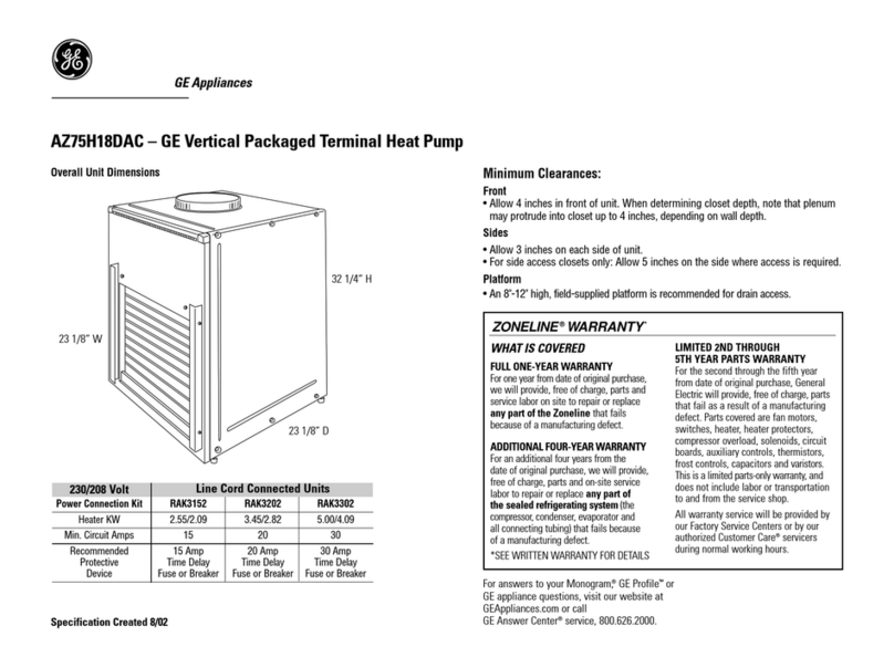
Popular Heat Pump manuals by other brands
alphainnoTec
alphainnoTec LWP operating manual

Garrison
Garrison 2498547 user manual

Viessmann
Viessmann VITOCAL 300-G PRO Type BW 2150 Installation and service instructions for contractors
Fedders
Fedders C12 Specification sheet
Mitsubishi Electric
Mitsubishi Electric SUHZ-SW VA Series installation manual

Daikin
Daikin FWXV15AVEB Service manual

Panasonic
Panasonic Secon H Series Installation and setup
Carrier
Carrier 50ZH Series Guide to operating and maintaining

Econar
Econar GeoSource 2000 GV Series Installation and operating instructions
HISEER
HISEER GSWW60 Installation, operation & maintenance manual
Trydent
Trydent E55 Installation instructions manual
Altherma
Altherma ERHQ011-016AA Technical data
