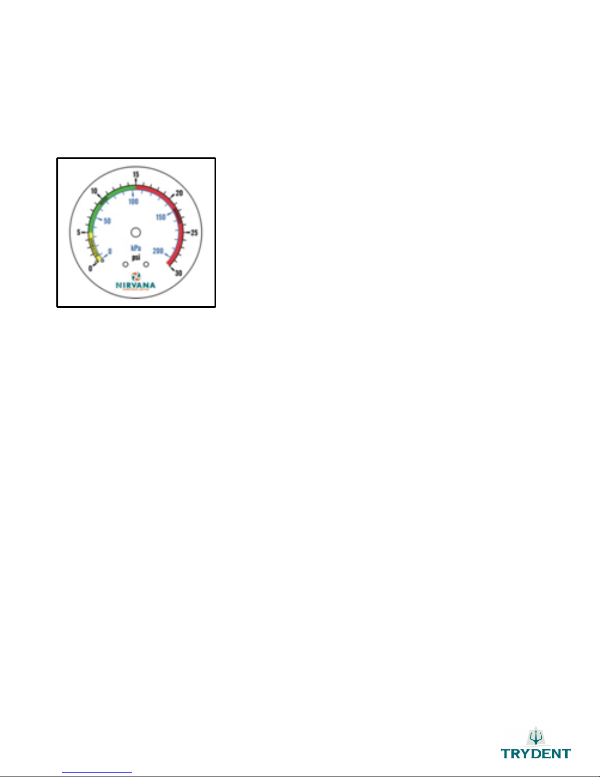
5.4 WATER PRESSURE GAUGE
The pipes connecting the different water filtration and heating components often include a large number of bypass
and/or service valves, sometimes leading to inadequate or no water pressure.
PICTURE 5
The pressure gauge should read between 5 and 15 Psi.
A high water pressure reading on the filter gauge does not necessarily mean
that enough water pressure is reaching the heat pump.
A good pressure should be held in the green section. If the pressure is in
the yellow section, you have to do a backwash. If the pressure is in red
section, you have a problem with the out water of the machine. It might
be a bad position of the bypass valve.
5.5 OPERATION OF THE HEAT PUMP
1. The swimming pool water pump must always be ON when the heat pump is in operation. If the swimming pool
water pump is equipped with a timer, make sure that the heat pump’s operating time is synchronized with the
water pump’s operating time, with priority to the pool heater. The pool heater may have to operate for longer
periods than the water pump of the swimming pool.
2. The heat pump may occasionally generate condensation in the form of mist when the relative humidity is at
higher levels.
3. The condensation formed on the heat collector may cause dripping under the heat pump.
4. The use of a bypass valve system is always recommended to facilitate maintenance.
5. When starting the heat pump, the fan will start immediately but the compressor will take between 3 and 5
minutes to start up.
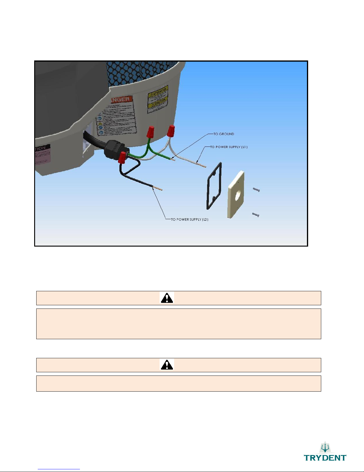
5.6 ELECTRICAL CONNECTION
The TRYDENT heat pump has been designed to enable simple, easy and safe installation. There is no need to open the
heat pump and risk making a mistake in the electrical hook-up.
All our models come with a junction box located at the base of the unit allowing quicker, simpler heat pump hook-up.
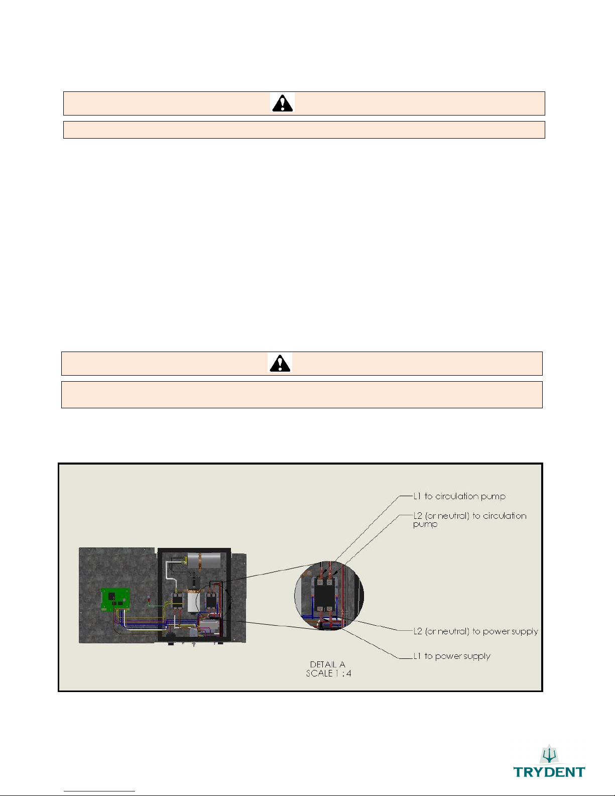
Note: You will find the heat pump’s electric plan at the end of this manual and on the inside of the electrical casing
of your unit. This one must be connected to a food of 240v single-phase current.


 Service manual")


