Nibe F2300 User guide

Installer manual
LEK
NIBE™ F2300
Air/water heat pump
IHB GB 1138-1
031741


Table of Contents
1 Important information 2
Safety information 2
2 Delivery and handling 7
Transport and storage 7
Assembly 7
Supplied components 10
Removing the side cover 11
3 The heat pump design 12
General 12
Junction box 14
4 Pipe connections 15
General 15
Pipe coupling heating medium circuit 15
Pressure drop, heating medium side 15
Docking alternatives 16
5 Electrical connections 17
General 17
Connections 18
Optional connections 20
Connecting accessories 21
6 Commissioning and adjusting 22
Preparations 22
Filling and venting the heating medium sys-
tem 22
Balance temperature 22
Stop temperature 22
Soft-starter 22
Compressor heater 22
Collar heater 22
Phase sequence control 22
Start-up and inspection 23
Readjusting, heating medium side 23
Adjustment, charge flow 24
7 Control - Introduction 25
General 25
Navigation 25
Display explanation 26
Control conditions 27
8 Control - Channels 29
Status channels 29
Temperature channels 29
Setting channels 29
9 Disturbances in comfort 31
Troubleshooting 31
10 Accessories 35
11 Technical data 36
Dimensions and setting-out coordinates 36
Sound pressure levels 37
Technical specifications 38
Electrical circuit diagram 40
Item register 44
1Table of Contents |NIBE F2300

Safety information
This manual describes installation and service procedures
for implementation by specialists.
This appliance is designed for use in a home environment
and not intended to be used by persons (including chil-
dren) with reduced physical, sensory or mental capabilit-
ies, or lack of experience and knowledge, unless they
have been given supervision or instruction concerning
use of the appliance by a person responsible for their
safety. This in accordance to applicable parts of the low-
voltage directive 2006/95/EC, LVD. The appliance is also
intended for use by experts or trained users in shops,
hotels, light industry, on farms and in similar environ-
ments. This in accordance to applicable parts of the ma-
chinery directive 2006/42/EC.
Children should be supervised to ensure that they do not
play with the appliance.
This is an original instruction manual. Translation is not
allowed without approval from NIBE.
Rights to make any design or technical modifications are
reserved.
©NIBE 2011.
Symbols
NOTE
This symbol indicates danger to machine or
person.
Caution
This symbol indicates important information
about what you should observe when maintain-
ing your installation.
TIP
This symbol indicates tips on how to facilitate
using the product.
Marking
F2300 is CE marked and fulfils IP24.
The CE marking means that NIBE ensures that the product
meets all regulations that are placed on it based on relev-
ant EU directives. The CE mark is obligatory for most
products sold in the EU, regardless where they are made.
IP24 means that the product is secure against penetration
by objects with a diameter larger than or equivalent to
12.5 mm and that the product is protected against drops
from all directions.
Safety precautions
Caution
Install the system in full accordance with this installation
manual.
Incorrect installation can cause bursts, personal injury, water leaks,
refrigerant leaks, electric shocks and fire.
Observe the measurement values before working on the
cooling system, especially when installing in small rooms, so
that the limit for the refrigerant's density is not exceeded.
Consult an expert to interpret the measurement values. If the refri-
gerant density exceeds the limit, lack of oxygen can occur in the
event of any leak, which can cause serious accidents.
Use original accessories and the stated components for the
installation.
If parts other than those stated by us are used, water leaks, electric
shocks, fire and personal injury may occur as the unit may not work
properly.
Ventilate the working area well – refrigerant leakage may
occur during service work.
If the refrigerant comes into contact with naked flames, poisonous
gas is created.
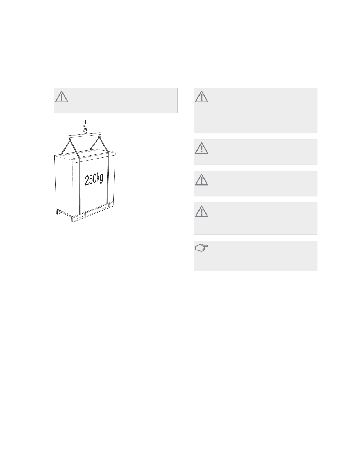
Install the unit in a location with good support.
Unsuitable installation locations can cause the unit to fall and cause
material damage and personal injury. Installation without sufficient
support can also cause vibrations and noise.
Ensure that the unit is stable when installed, so that it can
withstand earthquakes and strong winds.
Unsuitable installation locations can cause the unit to fall and cause
material damage and personal injury.
The electrical installation must be carried out by a qualified
electrician and the system must be connected as a separate
circuit.
Power supply with insufficient capacity and incorrect function can
cause electric shocks and fire.
Use the stated cables for the electrical connection, tighten
the cables securely in the terminal blocks and relieve the
wiring correctly to prevent overloading the terminal blocks.
Loose connections or cable mountings can cause abnormal heat
production or fire.
Check, after completed installation or service, that no refriger-
ant leaks from the system in gas form.
If refrigerant gas leaks into the house and comes into contact with
an aerotemp, an oven or other hot surface, poisonous gases are
produced.
Switch off the compressor before opening/breaching the re-
frigerant circuit.
If the refrigerant circuit is breached /opened whilst the compressor
is running, air can enter the process circuit. This can cause unusually
high pressure in the process circuit, which can cause bursts and
personal injury.
Switch off the power supply in the event of a service or in-
spection.
If the power supply is not shut off, there is a risk of electric shocks
and damage due to the rotating fan.
Do not run the unit with removed panels or protection.
Touching rotating equipment, hot surfaces or high voltage parts
can cause personal injury due to entrapment, burns or electric
shocks.
Cut the power before starting electrical work.
Failure to cut the power can cause electric shocks, damage and in-
correct function of the equipment.
Care
Carry out the electrical installation with care.
Do not connect the ground lead to the gas line, water line, lightning
conductor or telephone line's ground lead. Incorrect grounding can
cause unit faults such as electric shocks due to short-circuiting.
Use main switch with sufficient breaking capacity.
If the switch does not have sufficient breaking capacity, malfunctions
and fire can occur.
NIBE™ F2300Chapter 1 | Important information2
1 Important information

Always use a fuse with the correct rating in the locations
where fuses are to be used.
Connecting the unit with copper wire or other metal thread can
cause unit breakdown and fire.
Cables must be routed so that they are not damaged by
metal edges or trapped by panels.
Incorrect installation can cause electric shocks, heat generation and
fire.
Do not install the unit in close proximity to locations where
leakage of combustible gases can occur.
If leaking gases collect around the unit, fire may occur.
Do not install the unit where corrosive gas (for example ni-
trous fumes) or combustible gas or steam (for example thinner
and petroleum gases) can build up or collect, or where
volatile combustible substances are handled.
Corrosive gas can cause corrosion to the heat exchanger, breaks in
plastic parts etc. and combustible gas or steam can cause fire.
Do not use the unit where water splashes may occur, for ex-
ample in laundries.
The indoor section is not waterproof and electric shocks and fire
can therefore occur.
Do not use the unit for specialist purposes such as for storing
food, cooling precision instruments, freeze-conservation of
animals, plants or art.
This can damage the items.
Do not install and use the system close to equipment that
generates electromagnetic fields or high frequency harmonics.
Equipment such as inverters, standby sets, medical high frequency
equipment and telecommunications equipment can affect the unit
and cause malfunctions and breakdowns. The unit can also affect
medical equipment and telecommunications equipment, so that it
functions incorrectly or not at all.
Do not install the outdoor unit in the locations stated below.
- Locations where leakage of combustible gas can occur.
- Locations where carbon fibre, metal powder or other powder that
can enter the air.
- Locations where substances that can affect the unit, for example,
sulphide gas, chlorine, acid or alkaline substances can occur.
- Locations with direct exposure to oil mist or steam.
- Vehicles and ships.
- Locations where machines that generate high frequency harmonics
are used.
- Locations where cosmetic or special sprays are often used.
- Locations that can be subjected to direct salty atmospheres. In this
case, the outdoor unit must be protected against direct intakes of
salty air.
- Locations where large amounts of snow occur.
- Locations where the system is exposed to chimney smoke.
If the bottom frame of the outdoor section is corroded, or in
any other way damaged, due to long periods of operation,
it must not be used.
Using an old and damaged frame can cause the unit to fall and
cause personal injury.
If soldering near the unit, ensure that solder residue does not
damage the drip tray.
If solder residue enters the unit during soldering, small holes can
appear in the tray resulting in water leakage. To prevent damage,
keep the indoor unit in its packing or cover it.
Do not allow the drainage pipe to exit into channels where
poisonous gases, containing sulphides for example, can occur.
If the pipe exits into such a channel, any poisonous gases will flow
into the room and seriously affect the user's health and safety.
Insulate the unit's connection pipes so that the ambient air
moisture does not condense on them.
Insufficient insulation can cause condensation, which can lead to
moisture damage on the roof, floor, furniture and valuable personal
property.
Do not install the outdoor unit in a location where insects
and small animals can inhabit.
Insects and small animals can enter the electronic parts and cause
damage and fire. Instruct the user to keep the surrounding equip-
ment clean.
Take care when carrying the unit by hand.
If the unit weights more than 20 kg, it must be carried by two
people. Use gloves to minimize the risk of cuts.
Dispose of any packaging material correctly.
Any remaining packaging material can cause personal injury as it
may contain nails and wood.
Do not touch any buttons with wet hands.
This can cause electric shocks.
Do not touch any refrigerant pipes with your hands when
the system is in operation.
During operation the pipes become extremely hot or extremely cold,
depending on the method of operation. This can cause burn injuries
or frost injuries.
Do not shut off the power supply immediately after operation
has start.
Wait at least 5 minutes, otherwise there is a risk of water leakage
or breakdown.
Do not control the system with the main switch.
This can cause fire or water leakage. In addition, the fan can start
unexpectedly, which can cause personal injury.
Especially for units intended for R407C
- Do not use other refrigerants that those intended for the unit.
- Do not use charging bottles. These types of bottles change the
composition of the refrigerant, which makes the performance of
the system worse.
- When filling refrigerant, the refrigerant must always leave the
bottle in liquid form.
3Chapter 1 | Important informationNIBE™ F2300

Serial number
The serial number can be found at the top left of the rear
cover and on the foot of the product.
6HULDO QXPEHU
Caution
Always give the product's serial number when
reporting a fault.
Country specific information
Installer manual
This installer manual must be left with the customer.
NIBE™ F2300Chapter 1 | Important information4

Inspection of the installation
Current regulations require the heating installation to be inspected before it is commissioned. The inspection must be
carried out by a suitably qualified person. Fill in the page for information about installation data in the User manual.
DateSignatureNotesDescription
✔
Heating medium (page 15)
System flushed
System vented
Particle filter
Shut-off and drain valve
Charge flow set
Electricity (page 17)
Fuses property
Safety breaker
Earth circuit-breaker
Heating cable type/effect
Fuse size, heating cable (F3)
Miscellaneous
Condensation water pipe
Insulation condensation water pipe, thick-
ness (if KVR 10 is not used)
5Chapter 1 | Important informationNIBE™ F2300

Contact information
KNV Energietechnik GmbH, Gahberggasse 11, 4861 SchörflingAT
Tel: +43 (0)7662 8963-0 Fax: +43 (0)7662 8963-44
NIBE Wärmetechnik AG, Winterthurerstrasse 710, CH-8247 FlurlingenCH
Tel: (52) 647 00 30 Fax: (52) 647 00 31
Druzstevni zavody Drazice s.r.o, Drazice 69, CZ - 294 71 Benatky nad JizerouCZ
Tel: +420 326 373 801 Fax: +420 326 373 803
NIBE Systemtechnik GmbH, Am Reiherpfahl 3, 29223 CelleDE
Tel: 05141/7546-0 Fax: 05141/7546-99
Vølund Varmeteknik A/S, Member of the Nibe Group, Brogårdsvej 7, 6920 VidebækDK
Tel: 97 17 20 33 Fax: 97 17 29 33
NIBE Energy Systems OY, Juurakkotie 3, 01510 VantaaFI
Puh: 09-274 697 0 Fax: 09-274 697 40
NIBE Energy Systems Ltd, 3C Broom Business Park, Bridge Way, Chesterfield S41 9QGGB
Tel: 0845 095 1200 Fax: 0845 095 1201
NIBE Energietechniek B.V., Postbus 2, NL-4797 ZG WILLEMSTAD (NB)NL
Tel: 0168 477722 Fax: 0168 476998
ABK AS, Brobekkveien 80, 0582 Oslo, Postadresse: Postboks 64 Vollebekk, 0516 OsloNO
Tel. sentralbord: +47 02320
NIBE-BIAWAR Sp. z o. o. Aleja Jana Pawła II 57, 15-703 BIAŁYSTOKPL
Tel: 085 662 84 90 Fax: 085 662 84 14
© "EVAN" 17, per. Boynovskiy, Nizhny NovgorodRU
Tel./fax +7 831 419 57 06
NIBE AB Sweden, Box 14, Hannabadsvägen 5, SE-285 21 MarkarydSE
Tel: +46-(0)433-73 000 Fax: +46-(0)433-73 190
For countries not mention in this list, please contact Nibe
NIBE™ F2300Chapter 1 | Important information6

Transport and storage
F2300 must be transported and stored vertically.
NOTE
Ensure that the heat pump cannot fall over
during transport.
Assembly
႑Place F2300 outdoors on a solid level base that can
take the weight, preferably a concrete foundation. If
concrete slabs are used they must rest on asphalt or
shingle.
႑The concrete foundation or slabs must be positioned
so that the lower edge of the evaporator is at the level
of the average local snow depth, although a minimum
of 300 mm.
႑The F2300 should not be positioned next to sensitive
walls, for example, next to a bedroom.
႑Also ensure that the placement does not inconveni-
ence the neighbours.
႑F2300 must not be placed so that recirculation of the
outdoor air can occur. This causes lower output and
impaired efficiency.
႑Large amounts of condensation water as well as melt
water from defrosting can be produced. Condensation
water must be led off to a drain or similar (see page
8).
႑Care must be exercised so that the heat pump is not
scratched during installation.
LEK LEK
PLQ PP
Do not place F2300 directly on the lawn or other non
solid surface.
If there is a risk of roof falls, a protective roof or cover
must be erected to protect the heat pump, pipes and
wiring.
7Chapter 2 | Delivery and handlingNIBE™ F2300
2 Delivery and handling

Lift from the street to the set up location
If the base allows, the simplest thing is to use a pallet
truck to move the F2300 to the set up location.
NOTE
The centre of gravity is offset to one side (see
print on the packaging).
LEK
If F2300 must be transported across soft ground, for ex-
ample a lawn, we recommend that a crane that can lift
it to the set up location is used. When the F2300 is lifted
by crane the packaging must be untouched and the load
equally distributed with a boom, as illustrated above.
If a crane cannot be used F2300 can be transported using
an extended sack truck. F2300 must be used on the side
marked "heavy side" and two people are required to get
the F2300 up.
Lift from the pallet to final positioning
Before lifting remove the packaging and the securing
strap to the pallet.
Place lifting straps around each machine foot. Lifting from
the pallet to the base requires four persons, one for each
lifting strap.
It is not permitted to lift anything other than the machine
feet.
Scrapping
When scrapping, the product is removed in reverse order.
Lift by the bottom panel instead of a pallet!
Condensation water trough
The condensation water trough is used to collect and
lead away condensation water from the heat pump.
NOTE
It is important to the heat pump function that
condensation water is led away and that the
drain for the condensation water run off is not
positioned so that it may cause damage to the
house.
NOTE
Pipe with heating cable for draining the condens-
ation water trough are not included.
NOTE
To ensure this function the accessory KVR 10
should be used.
NOTE
The electrical installation and wiring must be
carried out under the supervision of an author-
ised electrician.
Caution
If none of the recommended alternatives is used
good lead off of condensation water must be
assured.
႑The condensation water (up to 100 litres/day) collec-
ted in the trough should be routed by pipe to an ap-
propriate drain, it is recommended that the shortest
outdoor stretch possible is used.
႑The section of the pipe that can be affected by frost
pipe must be heated by the heating cable to prevent
freezing.
႑Route the pipe downward from F2300.
႑The outlet of the condensation water pipe must be
at a depth that is frost free or alternatively indoors
(with reservation for local ordinances and regulations).
႑Use a water trap for installations where air circulation
may occur in the condensation water pipe.
႑The insulation must be tight against the bottom of
the condensation water trough.
NIBE™ F2300Chapter 2 | Delivery and handling8

Recommended alternatives
Stone caisson
LEK
Frostfritt dju
p
)URVW SURRI
GHSWK
If the house has a cellar the caisson must be positioned
so that it does not affect the house. Otherwise the caisson
can be positioned directly under the heat pump.
The outlet of the condensation water pipe must be at
frost free depth.
Drain indoors
:DWHU VHDO
The condensation water can be routed to a drain indoors
(with reservations for local rules and regulations).
Route the pipe downward from F2300.
The condensation water pipe must have a water trap to
prevent air circulation in the pipe.
Gutter drainage
LEK
Frostfritt
djup
)URVW
SURRI
GHSWK
:DWHU VHDO
The outlet of the condensation water pipe must be at
frost free depth.
Route the pipe downward from F2300.
The condensation water pipe must have a water trap to
prevent air circulation in the pipe.
9Chapter 2 | Delivery and handlingNIBE™ F2300

Installation area
The distance between F2300 and the house wall must
be at least 400 mm. Clearance above the F2300 should
be at least one metre.
400 mm
Fritt utrymme bakom
Fritt utrymme framför
Min. avstånd
vid användning
av flera F2300
600 mm
3000 mm
400 mm
Minimalt
fritt utrymme
600mm
Minimalt
fritt utrymme
0LQLPXP IUHH VSDFH
)UHH VSDFH EHKLQG
)UHH VSDFH LQ IURQW
0LQ GLVWDQFH ZKHQ XVLQJ VHYHUDO )
0LQLPXP IUHH VSDFH
Supplied components
LEK
Particle filterR322 pcs flexible pipes (R32)
NIBE™ F2300Chapter 2 | Delivery and handling10

Removing the side cover
LEK
11Chapter 2 | Delivery and handlingNIBE™ F2300

General
LEK
*4
(%
41 ;/
+6
;/
(%
3)
50 %7 %3
%7
;/
*4
(3
%7
%3
$$
41
(%
%3
41
41
41
:0
LEK
%7
(38%
;/
3)
;/
%7
;/
%7
$$
3)
%7
3)
NIBE™ F2300Chapter 3 | The heat pump design12
3 The heat pump design

Pipe connections
Connection, heating medium out of F2300,
G1 1/4” (Ø35mm)
XL 1
Connection,heating medium in to F2300,
G1 1/4” (Ø35mm)
XL 2
Service connection, high pressureXL 20
Service connection, low pressureXL 21
Connection, drip tray drainXL 40
HVAC components
4-way valveQN 2
Non-return valveRM 1
Condensation water troughWM 5
Sensors etc.
High pressure switch (29 bar)BP 1
Low pressure pressostatBP 2
High pressure switch (32 bar)BP 10
Temperature sensor, returnBT 3
Temperature sensor, condenser supply lineBT 12
Temperature sensor, hot gasBT 14
Temperature sensor, fluid pipeBT 15
Temperature sensor, evaporatorBT 16
Temperature sensor, suction gasBT 17
Temperature sensor, ambientBT 28
Electrical components
Joint card, sensorAA 100
Joint cardAA 101
Compressor heaterEB 10
Drip tray heaterEB 11
Collar heaterEB 13
FanGQ 1
Cooling components
EvaporatorEP 1
CondenserEP 2
CompressorGQ 10
Drying filterHS 1
Expansion valveQN 1
Solenoid valve, liquid injectionQN 30
Solenoid valve, gas injectionQN 31
Expansion valve, gas injectionQN 34
Miscellaneous
Type platePF 1
Serial numberPF 3
Cable gland, incoming supplyUB 1
Designations in component locations according to
standard IEC 81346-1 and 81346-2.
13Chapter 3 | The heat pump designNIBE™ F2300

Junction box
$$6 $$ $$6) ; ;
$$6
$$6
$$6
;
;
);$$
4$
4$
4$
4$
)%
LEK
)&
;
%$
$$
Electrical components
Relay card with power supply unitAA 6
Soft-start relayAA 10
Control card with displayAA 21
Plus buttonS1
Minus buttonS2
Enter buttonS3
Reset buttonS4
Display contrastSF 3
Phase sequence monitor (3-phase)BA 1
Fuse for external heating cable (250 mA)F3
Motor protectionFC2
Contactor, main contactorQA 51
Contactor, low speed fanQA 52
Contactor, high speed fanQA 53
Terminal block, incoming supplyX1
Terminal block, external supplyX2
Terminal block, charge pump, external heaterX3
Terminal block, common alarmX4
Terminal block, thermostat, compressor blockingX5
Terminal blockX6
Designations in component locations according to
standard IEC 81346-1 and 81346-2.
NIBE™ F2300Chapter 3 | The heat pump design14

General
Pipe installation must be carried out in accordance with
current norms and directives.
F2300 can only operate up to a return temperature of
about 55 °C and an outgoing temperature of about 65
°C from the heat pump.
F2300 is not equipped with external shut off valves on
the water side; these must be installed to facilitate any
future servicing. The return temperature is limited by the
return line sensor.
Water volumes
When docking with F2300 a minimum available system
volume of at least 20 litres per kW output on the heat
pump is recommended.
NOTE
The pipe work must be flushed before the heat
pump is connected, so that any contaminants
do not damage the components parts.
NOTE
The charge pump must be operational, even if
F2300 is not running, to prevent damage due
to freezing.
The charge pump can also be controlled directly from
F2300, terminal block (X3), which takes the ambient
temperature into consideration. Alternatively, the heat
pump is connected to an intermediate circuit with a heat
exchanger, pump and water with anti-freeze.
Pressure drop, heating medium
side
F2300 -14, 20
0
5
10
15
20
25
30
35
40
0 0,1 0,2 0,3 0,4 0,5 0,6 0,7 0,8 0,9 1,0 1,1
kPa
y
F
14 kW
20 kW
3UHVVXUH GURS
)ORZ
OV
N3D
L
+HDW LQVXODWLRQ
LEK
;/
;/
15Chapter 4 | Pipe connectionsNIBE™ F2300
4 Pipe connections

Docking alternatives
F2300 can be installed in several different ways, for ex-
ample with integrated or external control. The safety
equipment must be installed in accordance with current
regulations for all docking options.
See for more docking options.
When docking with F2300 a minimum available system
volume of at least 20 litres per kW output on the heat
pump is recommended.
NIBE™ F2300Chapter 4 | Pipe connections16

General
႑A heat pump must not be connected without the
permission of the electricity supplier and must be
connected under the supervision of a qualified electri-
cian.
႑If a miniature circuit breaker is used this should have
motor characteristic "C" (compressor operation). For
MCB size see "Technical Specifications".
႑F2300 does not include an omnipolar circuit breaker
on the incoming power supply. The heat pump’s
supply cable must be connected to a circuit-breaker
with at leasta3mmbreaking gap. When the building
is equipped with an earth-fault breaker the heat pump
should be equipped with a separate one. Incoming
supply must be 400 V 3NAC 50Hz via distribution
boards with fuses.
႑If an insulation test is to be carried out in the building,
disconnect the heat pump.
႑Connect control signal cable for thermostat to termin-
al (X5). Cable type: unscreened LiYY, screened LiYCY.
Cable area, at least 0.22with cable lengths less than
50m.
႑Alternatively the relevant screened signal cable is
connected from terminal (AA21:J2) to indoor module
from NIBE.
႑The routing of cables for heavy current and signals
should be made out through the cable glands on the
heat pump's right-hand side, seen from the front.
႑Charge pump for F2300 can be connected to separate
supply or to terminal block (X3).
NOTE! If F2300 is not powered and the charge pump
is connected to the terminal block (X3) there is a risk
of freezing
႑A common alarm can be connected to terminal (X4).
NOTE
Electrical installation and service must be carried
out under the supervision of a qualified electri-
cian. Electrical installation and wiring must be
carried out in accordance with the stipulations
in force.
NOTE
The live external control must be taken into
consideration when connecting.
$$ ; )
$$ ; ;
;;
$$-$$-
Accessibility, electrical connection
NOTE
The cover is opened using a Torx 20 screwdriver.
Removing electrical cabinet
Unscrew the screws and lift off the cover.
LEK
Dismantling motor junction box
Unscrew the screws and lift off the cover.
LEK
17Chapter 5 | Electrical connectionsNIBE™ F2300
5 Electrical connections

Connections NOTE
To prevent interference, unscreened communic-
ation and/or sensor to external connections
cables must not be laid closer than 20 cm to
high voltage cable when cable routing.
Power connection
LEK
LEK
,QFRPLQJ VXSSO\
&RQQHFWLRQ
Incoming supply cable is supplied and factory connected
to the terminal block -X1. Approx. 1.8 m cable is access-
ible outside the heat pump.
On installation the unions must be mounted on the rear
of the heat pump.
NIBE™ F2300Chapter 5 | Electrical connections18
Other manuals for F2300
4
Table of contents
Other Nibe Heat Pump manuals
Popular Heat Pump manuals by other brands

Kokido
Kokido K2O K880BX/EU Owner's manual & installation guide

Lennox
Lennox HPXA15-024 installation instructions

Sanyo
Sanyo SAP 122FCH Service manual

Carrier
Carrier 50CP Installation, Start-Up and Service Instructions

Aspira
Aspira ASPIRCOMFORT PRO X 460 H Installation, use and maintenance manual

Fujitsu
Fujitsu WOYA060LFCA Installation and operating manual

Dimplex
Dimplex AWP 30 HLW Installation and operating instructions

Daikin
Daikin FXFQ09PVJU Operation manual

Sanyo
Sanyo 09KH11W operating instructions

Dimplex
Dimplex SI 50TU Installation and operating instruction

Zodiac
Zodiac Z400 iQ Instructions for installation and use

Trane
Trane XL Series Weathertron Use and care