Metreco HVAC MK1 User manual

English v1-3
metreco
MANUAL
Metreco HVAC MK1

2
Declaration of Conformity
This is to certify that this equipment, designed and manufactured by Panimpex NV, Veurne-
straat 162, B-8660 De Panne, Belgium, meets the essential safety requirements of the Euro-
pean Union and is placed on the market accordingly. It has been constructed in accordance
with good engineering practice in safety matters in force in the Community and does not
endanger the safety of persons, domestic animals or property when properly installed and
maintained and used in applications for which it was made.
• Equipment Description :
• Applicable Directives :
• CE Implementation Date :
• Authorized Representative:
Metreco, electronic wireless measurement device
2014/30/EU; 2014/35/EU; 2014/68/EU; 2014/53/EU
14 September 2010
Bernard Peirs, CEO
Any questions relative to this declaration or to the safety of Metreco products should be di-
rected, in writing, to the support & quality assurance department at the above address.
Thank you for buying a Metreco!
Warnings & Dangers
-> Dangers and warnings indicated in this manual are marked with the following symbol:
IP64 : dust tight & splashingwater tight = don’t submerse or hold under tap upside down, •
can be used in the rain.
Do not open in order to prevent electrocution.•
Repair & maintenance should be done by qualied personel.•
Warranty is void if you have attempted to open the product or dismantle it.•
Don’t wet or short-circuit the battery charging contacts.•
For charging the batteries, only use the dedicated spaces in the charging station.•
Use only included AC adaptor for connecting the charging station to the mains.•
Use only included cigarette lighter plug for connecting the charging station to your 12V•
source (car etc.).
Use only a USB 2.0 compliant cable (included) with the correct plugs to connect the hand-•
held to the PC.
If irradiance occurs of an electromagnetic eld of 30 V/m at the frequencies of 325-340 •
MHz and 865-880 MHz, the wireless communication can get disturbed.
Working temperature: -30..+70 °C (for optimal battery capacity: -20..+60°C).•
Load batteries 12h before rst use.•
When stocking for longer period: keep the batteries at 50% charged.•
Contact:
www.metreco.com T +32 58 42 91 00
[email protected] F +32 58 42 14 46

3
Table of contents:
Declaration of Conformity
Warnings & Dangers
Table of contents
Metreco Concept
Working with Metreco
1. Basics
2. Conguration
3. Measuring
4. ACR
4.1. System management
• Create new ACR system
• Choose existing ACR system
• Edit current ACR system
• Remove existing ACR system
4.2. Performing measurement and Diagnosis
• Measurements
• Diagnosis
4.3. Logging & Reports
• Logging
• Measurement Report
• Intervention Report
4.4.Tests
• Pressure Decay Test
• Vacuum Decay Test
• COP Test
4.5. Customer & Systems follow-up
• Follow-up on Metreco
• Follow-up on PC
4.6. A word on ‘Sensor Placement’
4.7. How to use the hoses & connectors?
• Fill refrigerant
• Remove refrigerant
• Vacumize
5. Service & Support, Calibration and Updates
5.1. Service & Support
5.2. Calibration
5.3. Firmware updates
5.4. Extra Languages and Refrigerants
Technical data
• Metreco
• Sensors
Spare Parts

4
Metreco Concept
Thank you for choosing the Metreco Concept. This new way of working brings you
on the edge of the most recent technological possibilities in wireless developments
and gives you a huge competitive advantage.
SMART MOBILE MEASURING
Dynamic measuring with METRECO, Smart Mobile Measuring, instead of static •
measuring with traditional manifold with hoses and temperature probes.
Up to 10 sensors transmit their measurements simultaneously to the Handheld: •
no hoses - no lines.
The user positions himself where he wants/walks around and can read out the•
measurements in real time.
Intuitive/natural easy-to-use interface is operated with a capacitive touch-•
screen.
Dene your measurement/value targets - get a warning when they are o.•
Measurement - Diagnosis - Suggestions / Solutions.•
Database of serviced ACR systems available on Handheld & PC.•
Measurement reports on Handheld & PC.•
Intervention reports on Handheld & PC.•
Charge your handheld and sensor batteries in the specially designed case -•
docking station.
Extra hoses and connectors for handling refrigerant.•

5
• Scenario:
Engineer Jason services a system of a new client who claims that it ‘doesn’t cool’ any longer.
He places the sensors on the system: low pressure, high pressure and the two temperature
sensors. Jason has instantly, while walking around, access to the measurements in the ‘All
Sensors’ menu.
He creates a new client and system through the touchscreen of the Metreco. He chooses a
refrigerant and the targets for subcool, superheating and evaporator exit air temperature. He
is now looking at the ‘All Measurements’ level and has an instant idea of the measured and
calculated values. If one of the targets is o, he gets a warning with a diagnosis and a possible
cause.
The measured values can be logged, this creates automatically a Measurement report. Jason
also makes an Intervention report where he can keep track of the interventions he has done:
leak detection, lter-dryer, refrigerant adjustment, oil test, pressure test, vacuum test, etc.
Back at the oce Jason connects his Metreco handheld to his PC and makes a report for
internal use and a customer report which is sent by e-mail.
C
omp
re
s
s
o
r
F
ilter-
d
ryer
E
xpan
s
ionvalve
R
ec
ei
v
er
EVAPORATOR
CONDENSOR
HANDHELD

6
Working with Metreco
1. Basics
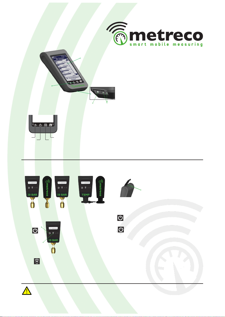
Metreco is supplied with:
- 1 Charging station - case
- 1 Low Pressure Sensor 20 Bar
- 1 High Pressure Sensor 50 Bar
- 2 Temperature sensors -50+150°C
- Metreco Handheld
- Adaptor 230V
- 12V cigarette lighter plug
- USB cable
- Space for 3 extra sensors
- Manual
- Set of hoses & connectors
- 4 Hoses (1/4”SAE-1:4”SAE: Red, Blue, 2*Yellow)
- 2 R410A adaptors (1/4”SAE Male - 5/16”SAE Female)
- 1 X-connector (4* 1/4”SAE Male)
- 2 T-connectors (1/4”SAE Female – 2* 1/4”SAE Male)
Space for 3
extra sensors
Sensors
Charging LED
Handheld
Lid with
protective foam
Storage
Socket for charging-
cable 12V & 220V
Hoses & Connectors
Batteries
Batteries have to be charged during
12hours before rst use!
- The case acts as the docking station for charg-
ing the batteries.
- Charging batteries: put the parts you want to
charge back in the case. Connect the charging-
cable to the 12V power supply in your car or the
230V(110V) AC.
Socket for chargingcable
12V & 220V
7
When your sensor has endured an overpressure of more than 2 times the max. pressure, you have
to recalibrate your sensor. (see 5. Service & Support, Calibration and Updates)
Handheld
Sensors
ON
OFF
1 Back
2 All Sensors
3 Main Menu
4 Logging
: Swipe to the right (->) 1-2-3-4 (min 1 s)
: Swipe to the left (<-) over 4-3-2-1
: back to preceding menu item
: to ‘All Sensors’
: to ‘Main Menu’
: start/stop logging
1 4
32
Touchscreen
Shortcuts
Power socketsUSB socket
Power sockets
ON
OFF
Calibration
Locate
Red LED
Green LED
: Push the button while the red LED ashes (2 s).
Flashing slows down once activated.
: Push the button for at least 2 s while the red LED
ashes quickly. Flashing stops when the sensor is O.
: Calibration (see 5.2 Calibration)
: Locate the sensor when assigning placement to sys-
tem (see ‘Step 10’ in 4.1 ACR System Management)
: ON/OFF & Data sending
: Calibration (see 5.2 Calibration)
ON / OFF
Calibration
&
Locate

8
2. Conguration
This is the list of parameters you can adapt:
- Units
- Language
- Log interval
- Date & Time
- Screen intensity
- Target Margins
- Update rmware (see 5.3.)
Units Language
Log interval
(go to ‘4.3. Logging’)
Date andTime
3. Change the congurations as desired.
2. Select ‘Congurations’.
Target margins
Screen intensity
1. Go to ’Main Menu’.
Modifying the target margins makes the Metreco more or less tolerant to target value variations
= quicker or slower reaction of the warning pop-up.
Main Menu

9
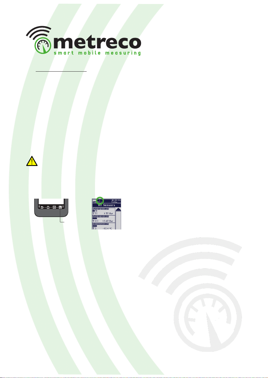
3. Measuring
In this part you learn how to quickly measure a pressure, temperature or vacuum:
1. Turn the device ON, slide to the right on the shortcut buttons (during min 1 s).
3. Place the sensors (temperature, pressure, vacuum) on the system and turn them on by
pressing at least for 2 seconds on the button.
4. Observe the measured values.
2. You will see the ‘All Sensors’ screen.
In chapter ‘4. ACR’ the following applications are treated:
- Creating a new ACR system
- Choosing an existing ACR system
- Diagnosis
- Logging
- Measurement report
- Intervention report
- Pressure Decay Test
- Vacuum Decay Test
- Follow-up on Metreco & PC
- Using the hoses & connectors
- Sensor calibration & rmware updates

10
4. ACR
In order to correctly apply the treated subjects of this chapter, we strongly advise you to
congure your handheld rst (go to ‘2. Congurations’).
4.1. ACR System management
You can dene and save ACR Systems on your Metreco.
1. Go to ‘Main Menu’.
2. Choose ‘ACR System’.
This menu gives you the possibility to:
- create a new ACR system
- choose an existing ACR system
- edit current ACR system
- remove an existing ACR system
1. Choose ‘New ACR System’ and select
‘Client’. Create a new one if needed or select
an existing one.
2. Choose ‘Name’ and complete the name
you want to give to the system
(a client can have many systems).
3. Select the refrigerant of the system.
-> This is an intelligent list. It will change the
order of your refrigerants according to the
frequency of selection of the refrigerants.
Most selected refrigerants will go on top.
•Create new ACR system
Main Menu

11
4. Determine the Superheat, Subcool and
evaporator exit air temperature target.
7. Assign the sensors, choose ‘Place sensors’
(If you haven’t physically put the sensors on the
system, put the sensors on the system).
9. Select a spot on the system. You will get
a list of available sensors eligible for this
position and whose signal is received.
10. You can also press the locate button
on the sensor. The sensor code will start
blinking on the handheld.
11. When all sensors are assigned (*), select
‘OK’ in the right bottom corner. This will give
you the ‘ACR Sytem’ again.
8. You have the possibility to assign pressure,
temperature, vacuum sensors and amperage
sensors. Or you can choose to give them a
name in generic sensors:
12. Select ‘Save System’ when all data is
correct. The system is saved. You get the
‘All Values’ menu with all the measured and
calculated values (You will get a warning if
you didn’t select or create a system.).
(*) (Sensors can only be assigned on a dened
ACR system.)
Warning ‘All Values’

12
If you have created and saved ACR systems, you can choose a system in your list of clients and
their systems. By choosing this, the placement of the sensors of your current system will be
lost.
All the necessary data is available, you don’t have to re-enter the data at each service:
4. Select the customer whose system you are
servicing.
5. Select the ACR system.
10. Observe the measured values in
‘All Values’.
• Choose existing ACR system
3. Select ‘Choose Existing ACR System’.
6. Change the data if necessary.
7. Check the targets.
8. ’Place sensors’ & ‘OK’.
9. ‘Save system’.
11. Consult Diagnosis. (see 4.2.)
12. Use the measured values in a
Measurement Report. (see 4.3.)
1. Go to ‘Main Menu’.
2. Select ‘ACR System’.
Main Menu

13
If you have created and saved ACR systems,
you can modify the data. The main idea is to
change the placement of the sensors while
servicing.
1. Repeat ‘Choose existing ACR system’ till
step 3 if you have chosen the system or till
step 5 if you still need to choose the system.
4. Change the placement of the sensors. By
selecting a placed sensor you can undo it’s
placement and assign it on a dierent spot.
(system can be saved without sensors being
placed).
5. Conrm with ‘OK’.
6. ‘Save System’.
• Edit current ACR system
Saved systems can be removed (deleted):
1. Select ‘Remove Existing ACR System’.
2. Select a client.
3. Select the system you want to remove.
4. Conrm removal of system.
• Remove existing ACR system
2. Change refrigerant if needed.
3. Change targets.
7. Continue your working procedure in ‘All
System Values’ and obeserve the measured
values while walking around.
Entire clients can only be removed on PC.

14
4.2. Performing measurement and diagnosis
• Measurements
Measurements, measured and calculated (in ‘All System Values’), can be performed from
the moment sensors are placed physically onto the ACR system. The sensors also need to be
‘placed’ on an existing system in Metreco. (‘ACR System’ - ‘Place Sensors’).
By combining dierent sensors, e.g. pressure and temperature, extra values can be
calculated.
This is the list of the dierent values that can be measured or calculated:
: Low pressure
: Saturated Evaporation temperature (refrigerant)
: Superheat
: High pressure
: Saturated Condensation temperature (refrigerant)
: Subcool
: Oil pressure
: Temperature low pressure side
: Temperature high pressure side
: Air temperature at condensor inlet
: Air temperature at condensor outlet
: Temperature Delta of air over condensor
: Air temperature at evaporator inlet
: Air temperature at evaporator outlet
: Temperature Delta of air over evaporator
: Pressure at condensor outlet
: Pressure Delta over condensor
: Pressure at lter outlet
: Pressure Delta over lter
: Pressure at evaporator inlet
: Pressure Delta over evaporator
: Vacuum pressure
(measured)
(calculated)
(calculated)
(measured)
(calculated)
(calculated)
(measured)
(measured)
(measured)
(measured)
(measured)
(calculated)
(measured)
(measured)
(calculated)
(measured)
(calculated)
(measured)
(calculated)
(measured)
(calculated)
(measured)
When saving a system, the placement of the sensors is not saved, this is a dynamic process.
(see ‘4.6. A word on Sensor Placement’)
- Values that don’t have a sensor assigned show ‘no sensor’.
- Calculated values which can’t be calculated due to missing sensor show what value they are
missing
- Values that are available are shown at the top of the list.
- LP
- Tevap
- SH
- HP
- Tcond
- SC
- POIL
- LT
- HT
- TACONDIN
- TACONDOUT
- DTAcond
- TAEVAPIN
- TAEVAPOUT
- DTAevap
- PCONDOUT
- DPcond
- PFILTOUT
- DPlt
- PEVAPIN
- DPevap
- PVAC

15
• Diagnosis
In this chapter you will learn how to use the diagnosis tool. Metreco can suggest possible
causes (*) for o-target measurements.
First of all you will need to dene targets for the following measurements:
Superheat Subcool Evaporator exit
air temperature
Check the dynamic history of every measured and calculated value and its divergence to the
dened target on your Metreco Handheld. Per sensor, the last 10 measured values are shown.
(*) This is a non-limited list that serves only as an indication. The engineer has to make his own diagnosis and has
to be in possession of the certicates mandatory by law and the knowledge to service ACR systems.
1. Select a value in ‘All Values’. 2. You will get a history of this value. If the
value has a dened target you can consult a
diagnosis (*) with possible causes.
3. By selecting ‘Plot history’ the data will be
plotted on the screen.
History Diagnosis (*)History
with target
1. Choose an ACR system (see 4.1.).
2. Dene the 3 targets and select ‘Done’.
3. From now on you will get a warning if a
value is o-target.
4. Select ‘OK’ to continue or ‘Value’ to check
the o-target value.
16
4.3. Logging & Reports
- Logging data creates a logle (.csv) and a Measurement Report
- Pressure Decay Test creates a logle (.csv) and a Pressure Decay Test Report (long & short)
- Vacuum Decay Test creates a logle (.csv) and a Vaccum Decay Test Report (long & short)
• Logging
When you apply ‘logging’, the measured values will be memorised with a standard interval of
5 seconds. This data can be used in Measurement Reports. You’re getting a list of saved data
(time & value) that you can retrieve from the Metreco on your PC via USB. This can then be
used for technical or commercial purposes (see ‘4.5. Customer & Systems follow-up’).
The standard interval between 2 loggings is 5 seconds. You can modify this interval in
the conguration menu (see ‘3. Conguration’).
1. Select ‘Logging’ to start the logging process. The logging icon ‘L’ will start blinking.
2. Select ‘Logging’ again to end the process. The logging icon ‘L’ will stop blinking.
When you end the logging process, a new Measurement report with the last logged measured
values is automatically created (see next point -> Measurement Report), all the logged values
are saved in a ‘LOG’ le (.csv).
There are over 1.000.000.000 data points...
Logging

17
• Measurement Report
- A Measurement Report is a survey of the performed measurements that you can use for tech-
nical and commercial purposes.
- A Measurement Report gives you the last logged measured values before ending the logging.
The report is saved automatically when ending the logging and can be recalled on Metreco and
downloaded on PC for later use in internal reports or reports to your customer.
5. The Measurement Report contains a
summary of:
- customer data
- system data
- placed sensors
- measurements
on Metreco
on PC (see ‘4.5. Customer & Systems follow-up’)
1. Follow the ‘Logging’ procedure as
explained in the preceding paragraph.
2. Select ‘Reports’ in the ‘Main Menu’.
3. Select Measurement Reports.
4. Select the customer, system and report.
Main Menu
18
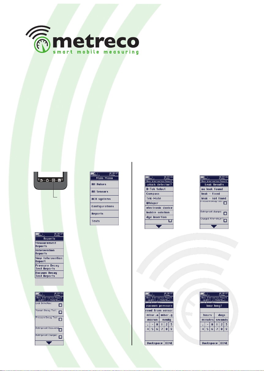
• Intervention Report
In the Intervention Report you can save data on the servicing you have done and recall the data
on Metreco or use it on your PC:
- Leak detection (leak detector & result)
- Vacuum decay test (possibility to store the vacuum sensor value)
- Pressure test with N2 or N2H2 (possibility to store the pressure sensor value)
- Refrigerant changes: recovered & charged
- Filter-dryer replaced?
- Oil test
- Refrigerant acid test & refrigerant moisture test
- Time spent on the job
- Notes
1. Select a system (see 4.1.). Intervention Reports can only be made when an ‘ACR system’ is
selected.
3. Select ‘New Intervention Report’.
4. Select ‘Leakdetector’.
2. Select ‘Main Menu’ and select ‘Reports’. 5. Select ‘Leak detector type’ and the result.
6. Select ‘Vacuum Decay Test’ .
7. Choose manual input or an existing report
(see ‘4.4. Tests’). When choosing manual in-
put, enter the measured value OR take a live
read-out from your vacuum sensor, if placed
on the installation and assigned in Metreco
(vacuum sensor not incl.).
8. Enter evacuation time.
Main Menu

19
12. Select ‘Refrigerant Recovered’ and enter
the quantity.
13. Select ‘Refrigerant Charged’ and enter the
quantity.
14. Scroll downwards.
15. Select ‘Oil test’ and enter the result.
9. Select ‘Pressure Decay Test’.
10. Choose manual input or an existing report
(see ‘4.4. Tests’). When choosing manual in-
put, enter the measured value OR take a live
read-out from your vacuum sensor, if placed
on the installation and assigned in Metreco.
11. Select the used gas (N2 or N2+H2)
17. Select ‘Moisture test’ and enter the result.
19. Select ‘Notes’ and add remarks.
16. Select ‘Acid test’ and enter the result.
20. Example of an Intervention Report on
Metreco (for use on PC see4.4.).
- Not all data has to be entered to create an Intervention Report.
- You will nd more explanations on the use of Reports on PC in the next chapter (4.5.).
- Recalling an Intervention Report is similar to recalling a Measurement Report (4.3.).
18. Select ‘Start/End’ and complete.

20
4.4.Tests
• Pressure Decay Test - PDT
The pressure decay test gives you the possibility to follow up and log the legaly imposed pres-
sure test. There is the possibility to automatically compensate the pressure for temperature
variations. A temperature and pressure sensor are what you need for this test.
2. Select ‘Pressure Decay Test’.
3. Complete the Pressure Decay Test Setup.
You must assign a pressure sensor
You are free to choose to assign a:
- System Temperature sensor
- Ambient Temperature sensor
- Target Pressure
- Pressure Medium (N2 or N2H2)
1. Select ‘Main Menu’ and select ‘Tests’. 4. Press ‘Start’
You get the Pressure Decay Test Status
5. End the PDT by pressing ‘Stop’.
You get the report.
6. Consulting the PDT:
- on the handheld can be done similarly as
a Measurement Report.
(See 4.3 - Measurement Report)
- on the PC can be done similarly as a
Measurement Report & Logle.
(See 4.5 - Follow-up on PC)
Main Menu
This manual suits for next models
1
Table of contents
Popular Handheld manuals by other brands


Motorola
Motorola MC75A quick start guide

Fujitsu Siemens Computers
Fujitsu Siemens Computers Pocket LOOX 710 operating manual

Motorola
Motorola MC9094 Guide

Intermec
Intermec Oracle-Ready CK31 user manual

Motorola
Motorola MC9090K - Win Mobile 6.1 624 MHz Specifications

Honeywell
Honeywell ScanPal Series user guide


