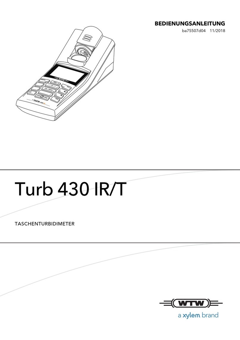
METRITEC DENSIT-RT6 User manual

M E T R I T E C G m b H K e e l e n g 1 3 D - 2 4 9 7 5 H u s b y G E R M A N Y
T e l e o n + 4 9 ( 0 ) 4 6 3 4 - 9 3 1 5 7 0 F a x + 4 9 ( 0 ) 4 6 3 4 - 9 3 1 5 7 1
s e r v i c e @ m e t r i t e c . d e w w w . m e t r i t e c . d e
DENSIT-RT6
Hand-probe Densitometer
battery powered
User Manual
ENGLISH

07-0400 Densit RT-6 DE.2020-08-11
2
Content
1. Measurement of the optical density...............................................................................3
2. General description.......................................................................................................4
3. Starting up: Inserting the batteries................................................................................6
4. Measuring mode...........................................................................................................7
4.1. Switching ON.........................................................................................................7
4.2. ZERO adjustment..................................................................................................8
4.3. Measuring procedure.............................................................................................9
4.4. HOLD function.....................................................................................................10
4.5. Switch OFF..........................................................................................................10
4.6. Setting the backlight ............................................................................................11
5. Calibration ..................................................................................................................12
5.1. One-factor calibration procedure..........................................................................15
5.2. Two-factor calibration procedure..........................................................................18
6. Battery indicator..........................................................................................................21
7. Technical data............................................................................................................22

07-0400 Densit RT-6 DE.2020-08-11
3
1. Measurement of the optical density
With radiographic testing, defects in technical equipment or components can be detected on the
basis of differences in density of the developed X-ray films. For quality assurance of the film
evaluation, the degree of blackening is determined as optical density. Optical density is measured
using the transmitted light method according to ISO 5-2 and ISO 5-3.
Optical density is defined by the decimal logarithm of the ratio of the luminance in front of the film
to the transmitted luminance behind the film:
= lg
D= diffuse optical density
L
0
= luminance in cd/m² "in front" of the film (without X-ray film)
L
F
= luminance in cd/m² "behind" the film (with X-ray film)
In practice, this formula means that at a measured density value of D = 1, one tenth (10%) of the
occurring light intensity is transmitted through the film, and a density value of D = 2 means that one
hundredth (1%) is let passed. An optical density value of D = 3 means that the film density lets
through one thousandth (0.1%) of the light intensity.

07-0400 Densit RT-6 DE.2020-08-11
4
2. General description
The DENSIT-RT6 handheld probe densitometer is a precise and reliable instrument for measuring
the density of technical X-ray films. It is used for the standard-compliant evaluation of radiographic
images. The portable densitometer is to be used together with a film viewer. The measured value
for the film density is the diffuse optical density Din the measuring range 0 to 5.
The DENSIT-RT6 consists of a handy measuring instrument and a hand-held probe connected by
a 1 m flexible cable.
Further features:
•sensor aperture 3 mm in diameter
•user-friendly keypad with 5 keys for on/off, measuring and calibrating function
•clear LCD digital display with 3-level backlighting
•powered by standard batteries (type AA)
•robust IP65-housing of plastic provided with a removable shock protection
•CE conformity marking
Handling: Avoid extreme cable buckling to prevent wire breakages. The probe cable is a high-
quality, flexible data cable. Its design and properties are is used as supply and data line. Its design
and properties are primarily intended to ensure functionality andcomfort in using.

07-0400 Densit RT-6 DE.2020-08-11
5
Keypad:
LIGHT
switching cyclically
between 3 levels
of backlighting
(p. 11)
HOLD
Measuring mode:
the last measured
value D is displayed
and frozen
(p. 10)
Calibrating mode:
confirm / save input /
quit
(p. 17, 19f)
UP
function key for
calibrating
(p. 15ff)
DOWN
function key for
calibrating
(p. 15ff)
ERO
ON-/OFF switch
(p. 7 / 10)
ZERO setting button
(p. 8)

07-0400 Densit RT-6 DE.2020-08-11
6
3. Starting up: Inserting the batteries
The DENSIT-RT6 is powered by 4 standard batteries 1.5 Volt
type AA. The required batteries are included in the delivery. For
reasons of transport safety, they are delivered in a separate box.
The battery compartment is located on the bottom of the
device. To insert the battery, first remove the blue shock
protection from the housing. Then loosen the 2 screws of
the battery cover.
Insert the four batteries, making sure the polarity is correct.
Close the cover again and put on the shock protection.
The densitometer is now ready for operation.
When removing and reattaching the blue shock protection, make sure that the probe and the probe
cable are not damaged.

07-0400 Densit RT-6 DE.2020-08-11
7
4. Measuring mode
4.1. Switching ON
Button Operation Display Commentary
press "ZERO" button
↓
program starts:
software version appears
wait for short
↓
"METRITEC" appears
briefly
↓
automatic zero setting
(after power-on)
the present Dvalue
is displayed
V02.0520
METRITEC
D=0.00
D=0.02

07-0400 Densit RT-6 DE.2020-08-11
8
4.2. ZERO adjustment
The diffuse optical density measurement is a relative measurement of the luminance with and
without film density. The reference value for the optical density of the radiographic image is the
luminous surface luminance without X-ray film. This reference value is to be set to zero before
each measurement.
press "ZERO" button
↓
zero setting:
"ZERO" appears briefly
Possible displays:
display okay
zero value has been set:
ready for measurement,
see 3.4
automatic
error display
luminance too low
for measurement
automatic
error display
luminance too bright
for measurement
ZERO
D=0.00
TOO DARK
toBright

07-0400 Densit RT-6 DE.2020-08-11
9
4.3. Measuring procedure
(a) Start with the zero adjustment. Hold the probe exactly vertical to the film viewer's internally
illuminated diffusion plate, as exactly as possible at the point where the X-ray film is to be
evaluated.
press "ZERO" button
↓
zero setting:
"ZERO" appears briefly
zero value has been set
(b) Place the X-ray film on the diffusion plate and hold the probe vertically on the spot where you
want to measure the film density.
read off value
the actual Dvalue
(c) The displayed measured value corresponds to the film density.
ZERO
D=0.00
D=4.38

07-0400 Densit RT-6 DE.2020-08-11
10
4.4. HOLD function
This function can be used to hold a current measured value. The density value is held flashing in
the display.
press "HOLD" button
the last measured
D value is maintained;
flashing display
press again
return to measuring
4.5. Switch OFF
keep "ZERO" pressed
for 3 seconds
device switches off
There should be a pause of about 5 seconds between switching the device off and on again.
D=3.12
OFF

07-0400 Densit RT-6 DE.2020-08-11
11
4.6. Setting the backlight
The digital display of DENSIT-RT6 has an orange backlight, which makes the operator's work
more comfortable. Three levels are available. By pressing the "LIGHT" key, the desired brightness
level can be set.
basic setting after switch-on
backlight level 1:
minimum brightness
press "LIGHT" button
backlight level 2:
medium brightness
press once again
backlight level 3:
maximum brightness
automatic downshift after 10 min.
return to basic setting
Note: The illumination level affects the power consumption of the device. For this reason, an
automatic switch-off function has been set up. If no key is pressed for 10 minutes, the lighting
switches off to save power.
D=0.02
D=0.02
D=0.02
D=0.02

07-0400 Densit RT-6 DE.2020-08-11
12
5. Calibration
The calibration of DENSIT-RT6 is done conscientiously by us as the manufacturer on a registered
BAM-tested reference density strip and should only be carried out by authorised specialists on an
annual basis. To avoid measurement errors, the quality of the film viewer and the reference density
strip should be ensured.
The DENSIT-RT6 is adjusted using two calibration factors A and B. This ensures a particularly
high accuracy over the entire measuring range..
Density: D= f(D, ∆D)
Calibrating equation: ∆D= A · f(D) + B
If unwanted deviations ∆D from the reference values are found due to the existing measurement
conditions, a re-calibration must be carried out. Check carefully whether this is necessary.
In many cases, setting factor A is sufficient for precise calibration. In other cases it might be
necessary to calibrate with factor B additionally.

07-0400 Densit RT-6 DE.2020-08-11
13
Calibration procedure overview:
Specials in Calibration Mode:
The asterisk "D
∗
" indicates the Calibration Mode.
3 decimal places are available for the calibration function.
The measuring procedure is unchanged and is started with the zero adjustment.
If calibration factor Ais being changed, the display is indicating e.g. DA=3.982.
If calibration factor Bis being changed, the display is indicating e.g. DB=0.883.

07-0400 Densit RT-6 DE.2020-08-11
14
Calibration procedure in detail:
Note: Example values. For reasons of clarity, "
∗
" and the third decimal place have been omitted in the presentation.

07-0400 Densit RT-6 DE.2020-08-11
15
5.1. One-factor calibration procedure
For an overview of the digital calibration procedure, see above pages 13 and 14.
The following is a step-by-step guide to one-factor calibration.
1) Enter Calibration Mode
+
keep both arrow keys
pressed for 3 seconds
starting Calibration Mode
wait for short
the present Dvalue
2) Zero adjustment
press "ZERO" button
↓
zero setting in CaliMode:
*ZERO* appears briefly
zero value has been set
Ca iMode
D
*
=3.962
*
ZERO
*
D
*
=0.00

07-0400 Densit RT-6 DE.2020-08-11
16
3) Set calibration factor A: Place the reference density strip (BAM) and measure a darker
reference value; for example D= 4.07
read of actual value
present deviation
∆D
from setpoint
or press or tap
one of the arrow keys
set factor A
release
adjusted actual value
4) To check the setting, measure the remaining reference values.
(if necessary continue on page 18)
5) There are two ways to end the calibration:
a) with Save = adopt new settings
b) without saving = reject the canges and cancel calibration
After exiting, the densitometer returns to normal measuring mode.
D
*
=4.01
4
DA=4.071
D
*
=4.073

07-0400 Densit RT-6 DE.2020-08-11
17
a) Quit CaliMode with saving
press "HOLD" button
"CaliSave" appears briefly
automatic query
Save Yes / No?
Cursor flashes "Y"
press "HOLD"
to confirm
new setting for factor A
has been saved,
quit CaliMode
b) Exit CaliMode without saving
press "HOLD" button
"CaliSave" appears briefly
automatic query
Save Yes / No?
Cursor flashes "Y"
m
ove cursor with
"UP" key
Save Yes / No?
Cursor flashes "N"
press "HOLD"
to confirm
cancel, new setting
for A not accepted,
exit CaliMode
Ca iSave
Y
ES/NO
Saved
Ca iSave
Y
ES/NO
Y
ES/
N
O
NotSaved

07-0400 Densit RT-6 DE.2020-08-11
18
5.2. Two-factor calibration procedure
For two-factor calibration, also start by adjusting calibration factor A. Start by following the step-by-
step guide from page 15 to point 4).
5) To then set calibration factor B, select a brighter reference value on the reference density
strip; for example D= 0.88.
read of actual value
present deviation
∆D
from setpoint
+
or
hold down "LIGHT"
while press or tap
one of the arrow keys set factor B
release adjusted actual value
Note: Keep to the sequence described above, first correct factor A before changing factor B!
D
*
=0.
923
DB=0.880
D
*
=0.88
1

07-0400 Densit RT-6 DE.2020-08-11
19
6) Now factor A must be recalibrated in any case (!). Repeat the steps from point 3 until the
nominal/actual value tolerance is maintained over the entire measuring range (see figure "2-
factor calibration", p.14 below).
7) End the two-factor calibration with or without saving:
a) quit CaliMode with saving
press "HOLD" button
"CaliSave" appears briefly
automatic query
Save Yes / No?
Cursor flashes "Y"
press "HOLD"
to confirm
new settings for A and B
have been saved,
quit CaliMode
Ca iSave
Y
E
S/NO
Saved

07-0400 Densit RT-6 DE.2020-08-11
20
b) exit CaliMode without saving
press "HOLD" button
"CaliSave" appears briefly
automatic query
Save Yes / No?
Cursor flashes "Y"
m
ove cursor with
"UP" key
Save Yes / No?
Cursor flashes "N"
press "HOLD"
to confirm
cancel, new settings for
A and B not accepted,
exit CaliMode
When the process is finished, the instrument returns to normal measuring mode.
Ca iSave
Y
ES/NO
Y
ES/
N
O
NotSaved
Table of contents
