manuals.online logo
Brands
  1. Home
  2. •
  3. Brands
  4. •
  5. Mitutoyo
  6. •
  7. Measuring Instrument
  8. •
  9. Mitutoyo LGF-110L-B User manual

Mitutoyo LGF-110L-B User manual

はじめに
本器の性能を十分に発揮させ、長期にわたり良好な状態でご使用いただくために、ご使用の前にはこのユー
ザーズマニュアルをよくお読みいただき、正しくお使いください。本書はお読みになった後も大切に保管し
てください。また、本器の仕様及び本書の内容は将来予告なしに変更することがあります。
安全に関するご注意
商品のご使用に当たっては、記載の仕様・機能・使用上の注意に従ってご使用ください。それ以外でご使用
になりますと安全性を損なうおそれがあります。
z先端の鋭利な測定子をご使用の場合には怪我をする恐れがありますので、交換作業時や使
用時には取扱いに十分ご注意ください。
z測定子を押し込んだ後に自由開放させると押し込み量によっては、測定子が非常に早いスピ
ードで突出する場合があります。指や手等を挟まれないように十分ご注意ください。
ご使用上の注意
以下の行為、状況は本器の故障誤動作の原因となりますのでお気を付けください。
重要
z落下などの急激なショック等の過度の力を加えないでください。
z分解、改造しないでください。
z直射日光のあたる場所、極端に熱い所、寒い所での使用、保管は避けてください。
z精度良くご使用していただくため、温度変化の激しい環境でのご使用はお避けください。
z電気ペン等の高電圧機器を使用した場合、電子部品が破壊される場合があります。また電気的ノイズの大
きい場所での使用は避けてください。
zスピンドルに対し垂直な方向の荷重や、ねじれがかかるような使用は避けてください。
z作動不良の原因となりますので、ステム部を必要以上に締めすぎないよう注意してください。
zケーブルに無理な力をかけないよう、また無理な曲げを与えないよう注意してください。
z安定した測定を行うには、通電後 10 分程度お待ちください。
zストローク両端を原点として使用しないでください。
z他の機器類などと組み合わせてご使用になる場合、環境や使用条件などにより性能が十分に発揮できない
場合がありますので、ご検討の上ご使用ください。
z仕様に示された条件以外で使用された場合、機能および性能の保証ができませんのでご注意ください。
z本製品が万一故障した場合の損害防止処置(安全対策)を十分に行ってください。
zワーク(測定物)の材質、測定力、測定子がワークに接触する時の衝撃、等により測定子がワークを傷つ
ける可能性があります。測定によるワークへの傷や精度等の問題がないことを事前に確認してからご使用
ください。
分別処理を行っている EU(欧州)諸国で電気・電子機器の破棄をする際の注意
商品または包装に記された左記のシンボルマークは、EU 諸国でこの商品を破棄する時に一
般家庭ゴミと一緒に捨てないようにするためもののです。WEEE(廃電気電子機器)を土壌に
埋め立てする量を減らし環境への影響を低減するために、商品の再利用とリサイクルにご協力
ください。処理方法に関するより詳しい内容は、お近くのお買い上げになった小売店や代理店
にお問い合わせください。
海外移転に関するご注意
本製品は「外国為替及び外国貿易法」の規制対象品です。製品や技術を海外移転する場合は、事前に弊社
にご相談ください。
1. 各部の名称と寸法
①ステム
②ゴムキャップ
③スピンドル
④測定子
➄出力ケーブル
⑥出力コネクタ
2. ゲージの取り付け方法
本器の装置、冶具への取付けは、φ8またはφ15 ステム部をクランプして行います。
取付け部の構造は、スリ割り入りホルダー又は割りブッシュを推奨致します。(実例1の推奨締付けトルク
0.4~0.5N・m)
重要
z止めネジで直接ステムを押し付ける方法は絶対避けてください。
(内蔵ベアリング破損の原因となります)
zステム部を強く締めすぎると、作動に支障をきたす恐れがありますので
ご注意くさださい。
zステム以外での固定方法は絶対にお止めください。
zゲージは測定面に対して垂直になるように取り付けてください。
傾けて取り付けますと測定結果に誤差を生じます。
zケーブルを通してゲージに力が加わらないようにご注意ください。
3. 防塵性・防水性についての注意事項
重要
z出力コネクタプラグやプリアンプ部(カウンタ側)は保護構造になっておりません。直接水や油のかから
ない場所に設置してください。
z延長ケーブルをご使用の際には、プリアンプ部および接続コネクタ部に露出がないように完全なシールを
施してください。
zケーブルの被覆が破れると、毛細管現象により液体がゲージ内部へ侵入し故障の原因となりますので、す
みやかに修理にお出しください。
z切粉などによりゴムキャップが破損しないように、十分注意の上ご使用ください。万一ゴムキャップが破
損した場合は、防塵防水性が損なわれますのですみやかに交換または修理にお出しください。
zゴムキャップや各シール部分に使用しているゴム等の材質は、多様化するクーラント、薬品などに対して
万能ではありません。これらが著しく劣化する場合には、最寄りの弊社営業所までご相談ください。
z水や油が頻繁にかかる環境で使用される場合には、破損前の予防的な交換を推奨致します。
z本器は各部にシールが施されているため、分解できない構造となっております。そのため、分解されます
と所定の性能を発揮できませんので絶対に分解しないでください。
4. ゲージとカウンタの接続
出力コネクタをリニヤゲージカウンタの入力コネクタに接続します。詳細はリニヤゲージカウンタのユーザ
ーズマニュアルを参照してください。
重要
z他の機器類の動力線とゲージのケーブルを近付けて使用しますと、誤動作の原因となりますので動力線か
ら離して配線してください。
z当社以外のカウンタ等と接続する場合は、ゲージへの電源投入後
0.2sec 以上おいてカウンタをリセットしてください。
5. ゲージの出力信号
1)出力コネクタ:RM12BPE-6PH(ヒロセ)
2)ピン配列
ピン NO 信号名 ピン NO 信号名 ピン NO 信号名
1 +5V ※3 3 φB 5 GND
2 φA 4 φA 6 φB
※3:ゲージヘッドへの供給電源
電源電圧:5V(4.8V~5.2V)、
リップル電圧:200mVp-p 以下、
消費電流:120mA
3)入出力信号レベル
φA、φA、φB、φB、(TTL ラインドライバ AM26LS31 相当)
4)出力信号チャート
本ゲージは出力信号に次の 3つの出力パターンを持っています。受信回路を設計する場合にはエラー検
出をするようにしてください。
(A)リアルタイムパルス出力 (スピンドル押込み時に A相進相)
①出力条件:スピンドル移動速度≦250mm/s ※4
②出力パルスの最小エッジ間隔:Tr (次表参照)
③出力遅れ時間 ※5:最大 1μs
リニヤゲージ LGF-110L-B/125L-B/150L-B/0510L-B/0525L-B/0550L-B/525L-B/550L-B No.99MBC102B
SeriesNo.542
LGF-0510L-B
LGF-110L-B
LGF-0550L-B
LGF-150L-B
LGF-550L-B
誤差=L0-L1
θ
LGF-0525L-B
LGF-125L-B
LGF-525L-B
1
2
3
4
6
5
φA
φB
Tr(最小)⇒0.5μm、1μm、5μm(分解能)
注意
※1:10mm ストロークタイプ用
※2:25/50mm ストロークタイプ用
断面
割りブッシュ
断面
※2
※1
切り欠き位置
+0.020
+0.005
単位:mm
・実例 2.
・実例 1.
1
※2
15
7.5
6
16
15
7.5
M4×0.7 通し
4.5 キリ、7.5 座グリ深さ 4.4
20 15
7.5
M4×0.7 通し
10
15
6
φ8
φ15
※2
※1
φ10
φ17
①
①
(タップに対し 90°)
②
②
15
1
φ15
φ8
※1
※2 φ17
φ10
※1
+0.024
+0.006
+0.020
+0.005
+0.024
+0.006
0
-0.015
0
-0.018
+0.020
+0.005
+0.024
+0.006
(B)バーストパルス出力 (スピンドル押込み時に A相進相)
応答速度がリアルタイムパルス出力の限界に達するとリニヤゲージは信号出力の形態をバーストパ
ルスに切替えます。通常のリアルタイムパルス出力の出力最小エッジ間隔より小さくしたもので、内
部クロックから強制的に作り出した 2相方形波信号です。バーストパルスは実際の動きに必ずしも忠
実に出力されず、信号の遅れは大きくなりますが出力が継続される限り計数値は有効です。
①出力条件:250mm/s ※4 <スピンドル移動速度≦ゲージの応答速度 ※6
②出力パルスの最小エッジ間隔:Tb (次表参照)
③出力遅れ時間 ※5:●1方向送り時=最大 5μs ●逆方向折返し時=最大 10μs
(C)エラー出力
振動・衝撃等により極端な波形の乱れが起こった場合やバーストパルス出力限界を超えて更に高速な
動きをすると、パルス発生回路は応答限界を超える場合があります。この時、出力信号をバーストパル
ス出力からエラーパルス出力に切替え、2相方形波信号の A相と B相を同期させますので、エラー検出
に使用して下さい。
①出力条件:下記条件にてゲージはエラー状態となり、上図の特殊パターンで出力します。
●ゲージの応答速度 ※6 <スピンドル移動速度
●ノイズ、振動等の外乱時
②出力パルスの最小パルス幅:Te (次表参照)
各条件での最小エッジ間隔/パルス幅
分解能 Tr(リアルタイム時) Tb(バースト時) Te(エラー時)
5μm 1μs 1μs 0.25μs
1μm 1μs 0.5μs 0.25μs
0.5μm 1μs 0.25μs 0.25μs
※4:この値に対して、実際のリアルタイムパルス出力の限界は低下します。これは実際の検出信号にはス
ピンドルの動きに含まれる加速度や、信号自体のわずかなノイズなどの誤差成分によるためで、理想
条件(一定速度・理想信号)以下の速度でバーストパルスが発生する場合があります。
※5:出力遅れ時間:スピンドルの位置に計数パルスが追いつくまでの時間
※6:ゲージの応答速度:ユーザーズマニュアルの仕様項を参照ください。
重要
zエラー時の出力は、計数データとして使えませんので、受信回路側でエラー状態を検出して下さい。
z5Mcps(方形波で 1.25MHz)以上の計数が可能な IC で設計することを推奨します。
5)入力コネクタ及び推奨入力回路コネクタ:RM12BRD-6S(ヒロセ)
6)ケーブル延長距離:延長ケーブル(別売)を使用して最大 20m まで可能です。
6. 保守
1)測定子の交換
付属品のキースパナをスピンドルのスパナ掛けにかけ、
測定子をペンチ等ではさんで取り外し/取り付けてください。
重要
zスピンドルを通してセンサ内部に力が加わると、
センサの破損や作動不良の原因となる恐れがあります。
必ずキースパナを使用してスピンドルを固定してください。
2)ゴムキャップの交換
破損前の予防的な交換を推奨致します。
(ゴムキャップは特別付属品として用意されています。)
(1)古いゴムキャップを取り外し、ステム及びスピンドルの溝部(A部)のゴミや油汚れをシンナー等で
きれいに取り除いてください。
(2)ゴムキャップの内径の大きい方がステム側になるように、測定子との間に挿入します。
(3)溝部(A部)に少量のシリコン系接着剤を塗布し、ゴムキャップを封止します。
重要
zこの際スピンドル摺動部に接着剤が付着すると、作動不良の原因になりますので充分注意してください。
7. 仕様
コード NO 542-161 542-162 542-163
符号 LGF-110L-B LGF-125L-B LGF-150L-B
分解能 1μm
精度(20℃) (1.5+L/50)μm L=任意測定長(mm)
出力信号周期 4μm
最小エッジ間隔 500ns
コード NO 542-171 542-172 542-173
符号 LGF-0510L-B LGF-0525L-B LGF-0550L-B
分解能 0.5μm
精度(20℃) (1.5+L/50)μm L=任意測定長(mm)
出力信号周期 2μm
最小エッジ間隔 250ns
コード NO - 542-612 542-613
符号 - LGF-525L-B LGF-550L-B
分解能 - 5μm
精度(20℃) - (7.5+L/50)μm L=任意測定長(mm)
出力信号周期 - 20μm
最小エッジ間隔 - 1000ns
測定範囲 10mm 25mm 50mm
測定子下向き 1.2N 以下 4.6N 以下 5.7N 以下
測定子横向き 1.1N 以下 4.3N 以下 5.3N 以下
測定力
測定子上向き 1.0N 以下 4.0N 以下 4.9N 以下
ステム径 φ8 φ15
共通仕様
●量子化誤差:±1 カウント ●位置検出方式:光電式透過型リニアエンコーダ
●応答速度:1.5m/s ※7
●出力方式:90°位相差差動方形波(RS-422A 適合)出力信号周期、最小エッジ間隔は上表参照
●測定子:φ3 超硬球(取付ねじ:M2.5×0.45)●軸受け方式:ストロークボールベアリング
●防塵防水性能:IP66 相当 ●出力ケーブル長:2 m (本体より直出し)
●使用温度(湿度):0~40℃(20~80%RH、非結露)
●保存温度(湿度):-10~60℃(20~80%RH、非結露)
●付属品:No.538610 測定子交換用キースパナ(10mm タイプ)
No.210187 測定子交換用キースパナ(25/50mm タイプ)
※7:50mm ストロークタイプの場合、測定子を押し込んだ後に自由開放させると、押し込み量によってはオ
ーバースピードエラーを発生する場合がありますので注意してください。
8. 特別付属品
●リニヤゲージ用延長ケーブル(5m):No.902434
●リニヤゲージ用延長ケーブル(10m):No.902433
●リニヤゲージ用延長ケーブル(20m):No.902432
●ゴムキャップ(10mm タイプ用):No.238772
●ゴムキャップ(25mm タイプ用):No.962504
●ゴムキャップ(50mm タイプ用):No.962505
スラストステムと締め付けナットを使用すると、ゲージ取り付け冶具はφ9.5 穴またはφ18 穴加工だけとな
り、しかも確実で簡単な取り付けが可能です。下記参照
●スラストステム(10mm タイプ用):No.02ADB681
●締め付けナット(10mm タイプ用):No.02ADB682
●専用スパナ(10mm タイプ用):No.02ADB683
●スラストステム(25/50mm タイプ用):No.02ADN371
●締め付けナット(25/50mm タイプ用):No.02ADB692
●専用スパナ(25/50mm タイプ用):No.02ADB693
=使用例=
重要
zスラストステムを取付ける場合は、必ず専用スパナ(02ADB683/02ADB693)でステムを固定してから取付けてく
ださい。本体とステムの間に無理な力が加わるとゲージ破損の原因となる恐れがあります。
zゲージ本体の M9.5×0.5/M14×0.5 ネジ部はスラストステム取付け用です。スラストステム取付け以外の目的に
は、使用しないでください。 Mitutoyo Corporation
Kawasaki、Japan
キースパナ(測定子交換用)
スパナ掛け部
測定子ゴムキャップ
(A)(A)
スパナ掛け
部
スピンドル
ステム
測定子ゴムキャップ
(A)(A)
スパナ掛け部スピンドル
ステム
LGF-0510L-B
LGF-110L-B
LGF-0525L-B
LGF-125L-B
LGF-525L-B
LGF-0550L-B
LGF-150L-B
LGF-550L-B
スラストステムセット(10mm タイプ用)
No.02ADB680
スラストステムセット(25/50mm タイプ用)
No.02ADN370
取付け部材の厚さ Lは、6~10.5 まで取り付け可能
取付け部材の厚さ Lは、10~13 まで取り付け可能
LGF-0525L-B
LGF-125L-B
LGF-0550L-B
LGF-150L-B
LGF-0510L-B
LGF-110L-B
φA
φB
Tb(最小)⇒0.5μm、1μm、5μm(分解能)
φA
φB
Te(最小)
φA,φB
φA,φB 推奨入力回路
LGF出力回路
26LS32 相当品
33pF
51Ω
GNDGND
+5V +5V
Foreword
To obtain the highest performance and the longest service life from your Linear Gage, carefully read this
manual thoroughly prior to setup and operation. After reading this manual keep it near the Linear Gage for
quick reference. The specifications of this gage and the description in this manual are subject to change
without prior notification.
Safety Precautions
To ensure operator safety, use the instrument in conformance with the directions and specifications given in
this User’s Manual.
zIf a contact point with a sharp tip is used, exercise sufficient care in handling during
replacement or use of it so as not to get hurt.
zIf a contact point is released freely after it has been pressed in, the contact point may burst
forth at a very high speed depending on the amount of spindle travel. Sufficiently exercise
care so that your fingers or hand may not be pinched.
Precautions for Use
Carefully avoid the following attempts and conditions to protect the instrument from failure and malfunction.
IMPORTANT
zDo not apply sudden shocks including a drop or excessive force to the linear gage.
zDo not disassemble or modify the gage.
z
Do not use and store the gage at sites where it is exposed to direct sunlight or at extremely hot or cold sites.
zTo use the gage highly accurately, avoid sites where the temperature will change abruptly.
zAbsolutely do not apply an electric engraver to the gage. The high voltage may damage electronic parts.
Also, do not use the gage at sites where it is subject to large electric noises.
zDo not exert load on the spindle in the perpendicular direction and do not twist the spindle.
zDo not clamp the stem too tightly, since the spindle will not move smoothly.
zDo not apply excessive tension to the cable or do not bend it forcibly.
zTo perform stable measurement, allow at least 10 minutes after turning on the power.
zDo not set up the origin point at either end of the stroke.
z
If the gage is used in combination with other instruments, the maximum performance could not be obtained
depending on environmental and operating conditions. Take those conditions into consideration prior to use.
z
The functions and performance will not be guaranteed, if the gage is used in other conditions than those specified.
zTale sufficient damage-preventive processing (safety measures), should this gage have been at fault.
zA contact point could hurt a workpiece depending on the workpiece material, measuring force, impact
when the contact point comes in contact with the workpiece, etc. Check that there is no problem of hurts
on a workpiece during measurement or accuracy variation depending on the measuring force, etc., in
advance of use.
Disposal of Old Electrical & Electronic Equipment (Applicable in the European
Union and other European countries with separate collection systems)
This symbol on the product or on its packaging indicates that this product shall not be treated
as household waste. To reduce the environmental impact of WEEE (Waste Electrical and
Electronic Equipment) and minimize the volume of WEEE entering landfills, please reuse
and recycle.
For further information, please contact your local dealer or distributors.
Export Control Compliance
The goods, technologies or software described herein may be subject to National or International, or
Japanese Export Controls. To export directly or indirectly such matter without due approval from the
appropriate authorities may therefore be a breach of export control regulations and the law.
1. Name and Dimension of Each Part
(1) Stem
(2) Rubber boot
(3) Spindle
(4) Contact point
(5) Output cable
(6) Output connector
2. Mounting the Gage
To mount the gage on another instrument or a fixture, clamp the Φ8 stem or Φ15 stem.
It is recommended to use a slotted holder or a split bushing for the mount structure.
IMPORTANT
zAbsolutely avoid pressing the stem directly with set screws.
(The built-in bearing may be damaged.)
zNotice that excessively tightening the stem can cause trouble in the spindle operation.
zNever fix a linear gage at other than the stem.
zMount the gages so that the spindle is directed perpendicular to
the measured surface. If the gage is mounted at an angle to the measured surface,
an error may be generated in measurement results.
zExercise care so as not to exert a force on the gage through the cable.
3. Precautions in Protecting the Gage from Dust and Water
IMPORTANT
zThe output connector plug and preamplifier (counter side) is not protective structured. Install the gage at a
place where it is not splashed directly with water or oil.
zIf an extension cable is used, completely cover the preamplifier and connector area with a seal so as not to
be exposed to environments.
zIf the cable covering is broken, liquid will penetrate into the gage inside due to capillary phenomenon. This
will cause damage to the gage. Immediately repair the cable.
zBe greatly careful not to damage the rubber boot due to chips, etc. If the rubber boot is damaged,
dust-proof function will be deteriorated. Immediately replace or repair the rubber boot.
zThe materials including rubber which are used for the rubber boot and other sealing parts are not universal
against diversified coolants and chemicals. If those parts deteriorate unusually, consult the nearest
Mitutoyo Service Center.
zIf linear gages are used in adverse environments where they are subject to frequent splashes of water and
oil, it is recommended to take preventive measures such as replacing them before being damaged.
zEach part of the gage is sealed up, and therefore must not be disassembled. If any part is disassembled,
the rated performance will not be obtained. Do not absolutely disassemble the gage.
4. Connecting the Gage to a Counter
Connect the output connector of the gage to the input connector on a linear gage counter. For detailed
information, refer to the user’s manual of the linear gage counter.
IMPORTANT
zIf the gage cable is close to the power line for other instruments, the gage may malfunction. Connect the
gage cable as apart from the power line as possible.
zIf the gage is connected with other counter than Mitutoyo made, allow at least 0.2 second after the gage is
turned on, then reset the counter.
5. Gage Output Signals
1) Output connector: RM12BPE-6PH (Hirose)
2) Pin assignment
Pin No. Signal name Pin No. Signal name Pin No. Signal name
1 +5V *3 3 ΦB 5 GND
2 ΦA 4 ΦA 6 ΦB
*3: Power supply to the gage head
Power voltage; 5V (4.8N to 5.2V),
Ripple voltage: 200mVp-p or less
Current consumption: 120mA max.
3) Input/output signal level
ΦA, ΦA, ΦB, ΦB, ΦZ (TTL line driver AM26LS31 or equivalent)
4) Output signal chart
This series of gages are provided with the following three patterns for their output signals. Therefore,
always design the reception circuitry so that it includes an error detecting process making use of these
patterns:
(A) Real-time pulse output (Phase-A wave advances when the spindle is retracted.)
(1) Output condition: Spindle moving speed ≤250mm/s *4
(2) Minimum edge-to-edge interval of output pulses: Tr (See the following table.)
(3) Output delay time *5: Max. 1μs
(Hirose)
(Thread height)
Cable length = 2m
Thrust stem
mounting screw
26 or more
(stroke)
Linear Gage LGF-110L-B/125L-B/150L-B/0510L-B/0525L-B/0550L-B/525L-B/550L-B No. 99MBC102B
Series No. 542
LGF-0510L-B
LGF-110L-B
LGF-0525L-B
LGF-125L-B
LGF-525L-B
ΦA
ΦB
Tr (minimum) ⇒ 0.5μm, 1μm, 5μm (resolution)
NOTE
*1:For 10mm Stroke type
*2:For 25/50mm Stroke type
Cross section
Split bushing
Cross section
*2
*1
(90°with respect to tap)
+0.020
+0.005
Unit: mm
・Example2
・Example1
1
*2
15
7.5
6
16
15
7.5
M4 x 0.7 thru
4.5 drill, 7.5 countersink, 4.4deep
20 15
7.5
M4×0.7thru
12
15
6
Φ8
Φ15
*2
*1
Φ10
Φ17
(1)
(1)
Notch position
(2)
(2)
15
1
Φ15
Φ8
*1
*2 Φ17
Φ10
*1
+0.024
+0.006
+0.020
+0.005
+0.024
+0.006
0
-0.015
0
-0.018
+0.020
+0.005
+0.024
+0.006
1
2
3
4
6
5
(Thread height)
(Hirose)
Cable length = 2m
(Thrust stem mounting screw)
10.6 or more
(stroke)
(
Hirose
)
(Thread height)
Cable length = 2m
Thrust stem
mounting screw
51.5 or more
(stroke)
LGF-0550L-B
LGF-150L-B
LGF-550L-B
Error = L0 - L1
θ
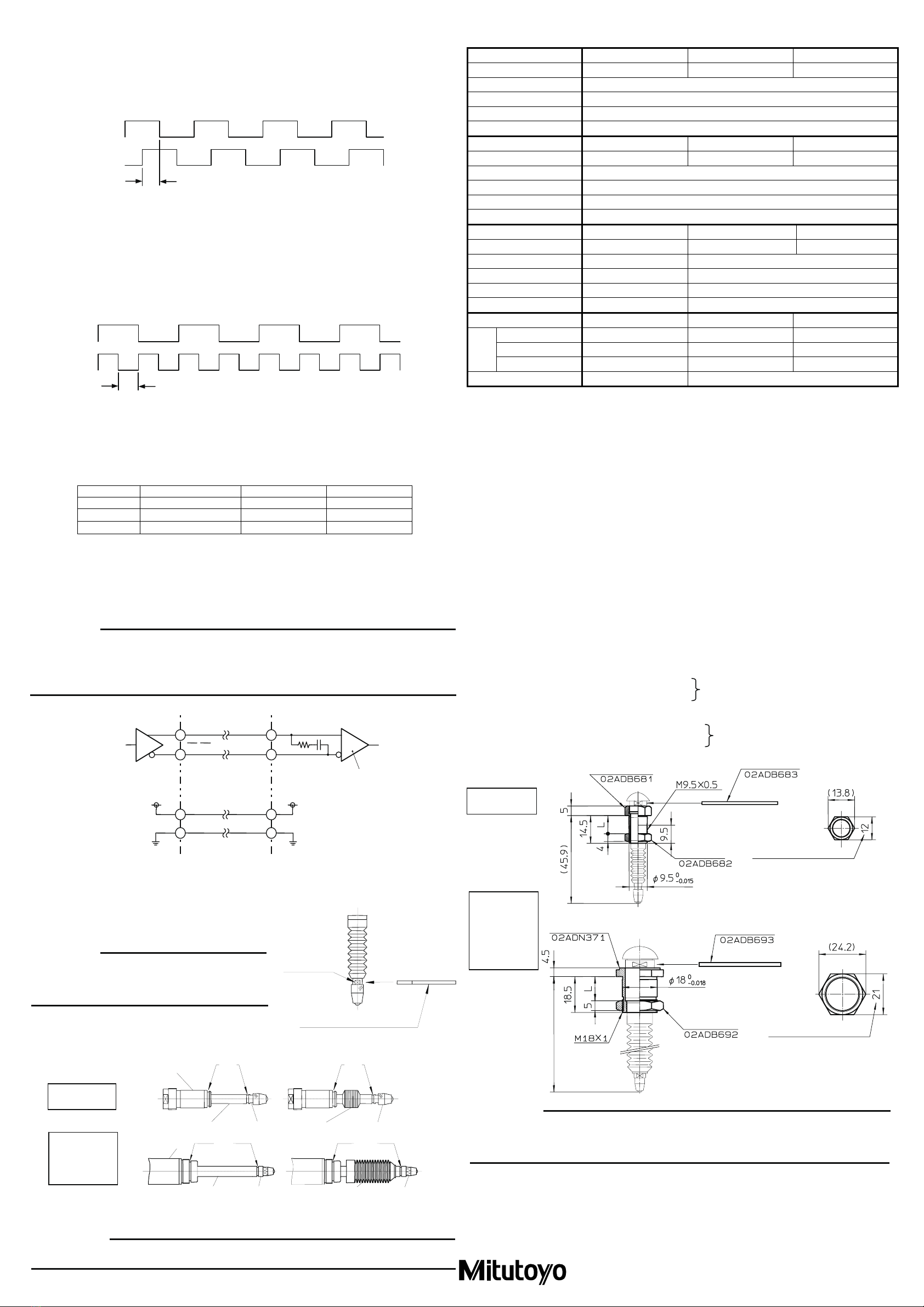
(B) Burst pulse output (Phase-A wave advances when the spindle is retracted.)
When the response speed reaches the speed limit of real-time pulse output, the linear gage will switch
its signal output form to that consisting of burst pulses. At this time, these burst pulses will be such
2-phase square wave signals that are forcibly created from the internal clock so the minimum
edge-to-edge interval in their output is smaller than the normal real-time pulse output. The burst pulses
will not always be outputted so as to exactly reflect the actual motion and the delay in signals also
becomes larger, but the counting values will be still valid as long as this output form continues.
(1) Output condition: 250 mm/s *4 < Spindle moving speed ≤Gage response speed *6
(2) Minimum edge-to-edge interval of output pulses: Tb (See the following table.)
(3) Output delay time *5: ●When feeding the spindle forward = Max. 5 μs
●When returning the spindle backward = Max. 10 μs
(C) Error output
The pulse generation circuit may sometimes overstep its response limit, if the output wave is subject to
extreme disturbance due to vibration or impact in the gage unit, or if the spindle moves faster beyond
the output limit of burst pulses. However, at this time, as the linear gage will automatically switch its
output signal form from burst pulses to error pulses and also synchronize Phase A and Phase B of the
2-phase square wave signals, the user can make use of this facility for error detection.
(1) Output condition: The gage will be identified as error under the following conditions and
produce its output in one of the above described special patterns.
●Gage response speed *6 < Spindle moving speed
●At a disturbance such as noise interference, vibration, etc.
(2) Minimum edge-to-edge interval of output pulses: Te (See the following table.)
Minimum edge-to-edge interval / pulse width under each condition
Resolution Tr (for real-time pulse) Tb (for burst pulse) Te (for error pulse)
5μm 1μs 1μs 0.25μs
1μm 1μs 0.5μs 0.25μs
0.5μm 1μs 0.25μs 0.25μs
*4: The actual limit of real-time pulse output will be depreciated to this value. This is because actual detection
signals unavoidably contain acceleration components in association with the spindle motion as well as
error components from a minute noise included in the signal itself. As a result, some burst pulses at a
speed below the ideal conditions (i.e. ideal signal form at constant speed) may be generated.
*5: Output delay time: Time until the counting pulse catches up the spindle position
*6: Gage respond speed: Refer to the section of specifications of the Users Manual.
IMPORTANT
zSince any output during error can not be used as the attribute data, it is necessary to detect the error
condition at the reception circuitry side.
zIt is recommended to design user circuitry based on an IC chip that is capable of counting at 5 Mcps
(equivalent to a square wave of 1.25 MHz) or greater.
5) Input connector and recommended input circuit connector: RM12BRD-6S (HIROSE ELECTRIC)
6) Cable extendible length: The cable can be extended up to 20m using the extension cable (optional).
6. Maintenance
1) Replacing the contact point
Fit the supplied key spanner in the keyway of the spindle, then detach or
attach the contact point by pinching it with a wrench, etc.
IMPORTANT
If torque is applied to the sensor inside through the spindle,
damage or malfunction in the sensor may result. Be sure to
fix the spindle using the key spanner.
2) Replacing the rubber boot
Preventive replacement before being damaged is recommendable.
(The rubber boot is available as an optional accessory.)
(1) Remove the old rubber boot, then eliminate the dust and dirt in the grooves (part A) of the stem and spindle.
(2) Insert a rubber boot between the stem and contact point, directing the greater inside diameter end to the stem.
(3) Apply a small amount of silicone adhesive to the grooves (part A), and seal both ends of the rubber boot.
IMPORTANT
If the adhesive is applied to the spindle, the spindle will not slide properly. Great care must be exercised.
7. Specifications
Order NO. 542-161 542-162 542-163
Model No. LGF - 110L - B LGF – 125L - B LGF – 150L - B
Resolution 1μm
Accuracy (at 20 ℃) (1.5 + L/50) μm L = Measured length in mm
Output signal pitch 4μm
Minimum edge interval 500ns
Order NO. 542-171 542-172 542-173
Model No. LGF – 0510 L - B LGF – 0525L - B LGF – 0550L - B
Resolution 0.5μm
Accuracy (at 20 ℃) (1.5 + L/50) μm L = Measured length in mm
Output signal pitch 2μm
Minimum edge interval 250ns
Order NO. - 542-612 542-613
Model No. - LGF – 0525L - B LGF – 0550L - B
Resolution - 5μm
Accuracy (at 20℃) - (7.5 + L/50)μm L= Measured length in mm
Output signal pitch - 20μm
Minimum edge interval - 1000ns
Measuring range 10mm 25mm 50mm
Contact point downwards 1.2 N or less 4.6 N or less 5.7 N or less
Contact point horizontal 1.1 N or less 4.3 N or less 5.3 N or less
Meas.
force
Contact point upwards 1.0 N or less 4.0 N or less 4.9 N or less
Stem Diameter Φ8 Φ15
Specifications common to all series
●Quantizing error: ±1 count ●Positional sensor: Photoelectric transmission linear encoder
●Response speed: 1.5m/s *7
●Output method: 90°phase differential square wave (compatible with RS-422A)
Refer to the above table for Output Signal pitch and Minimum edge interval
●Contact point: Φ3 carbide ball(Thread: M2.5x0.45) ●Bearing type: Stroke ball bearing
●Protection level: IP66 ●Output cable length: 2m(directly wired from the gage)
●Operating temperature (humidity) :0 to 40 ℃ (20 to 80%RH, with no condensation)
●Storage temperature (humidity) : -10 to 60 ℃ (20 to 80%RH, with no condensation)
●Accessory: No. 538610 Key spanner for contact point replacement (10mm type)
No. 210187 Key spanner for contact point replacement (25/50mm type)
*7: In the case of 50mm stroke type, an over speed error may occur depending on the spindle retraction
amount, if the contact point is released freely after it is retracted.
8. Optional Accessories
●Extension cable(5m) : No. 902434
●Extension cable(10m) : No. 902433
●Extension cable(20m) : No. 902432
●Rubber boot (for 10mm type) : No. 238772
●Rubber boot (for 25mm type) : No. 962504
●Rubber boot (for 50mm type) : No. 962505
If the thrust stem and tightening nut are used, the gage mount fixture needs only Φ9.5 or Φ18 hole to be
drilled, and also the gage can be mounted firmly and easily. (see below.)
●Thrust stem (for 10mm type) :No. 02ADB682
●Tightening nut (for 10mm type) :No. 02ADB682
●Dedicated spanner (for 10mm type) : No. 02ADB683
●Thrust stem (for 25/50mm type) :No. 02ADN371
●Tightening nut (for 25/50mm type) :No. 02ADB692
●Dedicated spanner (for 25/50mm type) :No. 02ADB693
=Example of use=
IMPORTANT
zBefore mounting the trust stem, be sure to secure the stem using the dedicated spanner (No.02ADB683/
No.02ADB693). Excessive force applied between the gage body and stem may cause damage to the
gage.
zM9 x 0.5/M14 x 0.5 screw are sued only for mounting the trust stem. Do not use them for other purposes.
Mitutoyo Corporation
Kawasaki、Japan
Dimension between
hexagonal opposing sides
Thrust stem / Mounting nut
( Optional accessories )
Mounting nut
Dedicated spanner
( Optional accessories )
Thrust stem
( Optional accessories )
LGF-0510L-B
LGF-110L-B
LGF-0525L-B
LGF-125L-B
LGF-525L-B
LGF-0550L-B
LGF-150L-B
LGF-550L-B
Thrust stem set (for 10mm type)
No.02ADB680
Thrust stem set (for 25/50mm type)
No.02ADN370
Fixture width L: within 6 to 10.5mm
Fixture width L: within 10 to 13mm
LGF-0525L-B
LGF-125L-B
LGF-0550L-B
LGF-150L-B
LGF-0510L-B
LGF-110L-B
ΦA
ΦB
Tb (minimum) ⇒ 0.5μm, 1μm, 5μm (resolution)
ΦA
ΦB
Te (minimum)
ΦA, ΦB
ΦA, ΦB
Recommended input circuitLGF output circuit
26LS32 or equivalent
33pF
51Ω
GNDGND
+5V +5V
Key spanner
(for replacing contact points)
Key Way
Contact pointRubber boot
Key WaySpindle
Stem ( A ) ( A )
Contact pointRubber boot
Key WaySpindle
Stem ( A ) ( A )
( Optional accessories )
Thrust stem Dedicated spanner
Mounting nut Thrust stem / Mounting nut
Dimension between
hexagonal opposing sides
For 25mm stroke = (84.1)
For 50mm stroke = (124.9)

This manual suits for next models

10

Other Mitutoyo Measuring Instrument manuals

Mitutoyo 209 Series User manual

Mitutoyo

Mitutoyo 209 Series User manual

Mitutoyo 7210 User manual

Mitutoyo

Mitutoyo 7210 User manual

Mitutoyo HDS-H30C User manual

Mitutoyo

Mitutoyo HDS-H30C User manual

Mitutoyo ID-C Series User manual

Mitutoyo

Mitutoyo ID-C Series User manual

Mitutoyo ID-SX2 User manual

Mitutoyo

Mitutoyo ID-SX2 User manual

Mitutoyo 99MAB034A1 User manual

Mitutoyo

Mitutoyo 99MAB034A1 User manual

Mitutoyo LG200 User manual

Mitutoyo

Mitutoyo LG200 User manual

Mitutoyo 209 Series User manual

Mitutoyo

Mitutoyo 209 Series User manual

Mitutoyo MDH User manual

Mitutoyo

Mitutoyo MDH User manual

Mitutoyo LGB User manual

Mitutoyo

Mitutoyo LGB User manual

Mitutoyo LGB2 User manual

Mitutoyo

Mitutoyo LGB2 User manual

Mitutoyo ID-CNX Series User manual

Mitutoyo

Mitutoyo ID-CNX Series User manual

Mitutoyo QM-Height User manual

Mitutoyo

Mitutoyo QM-Height User manual

Mitutoyo ID-SX User manual

Mitutoyo

Mitutoyo ID-SX User manual

Mitutoyo EJ-102N User manual

Mitutoyo

Mitutoyo EJ-102N User manual

Mitutoyo ID-U User manual

Mitutoyo

Mitutoyo ID-U User manual

Mitutoyo QM-Height Series User manual

Mitutoyo

Mitutoyo QM-Height Series User manual

Mitutoyo IMZ-MJ User manual

Mitutoyo

Mitutoyo IMZ-MJ User manual

Mitutoyo QM-Data 300 User manual

Mitutoyo

Mitutoyo QM-Data 300 User manual

Mitutoyo LGH Series User manual

Mitutoyo

Mitutoyo LGH Series User manual

Mitutoyo ID-H0530 User manual

Mitutoyo

Mitutoyo ID-H0530 User manual

Mitutoyo LGF-110ZL-B User manual

Mitutoyo

Mitutoyo LGF-110ZL-B User manual

Mitutoyo TI-1XX User manual

Mitutoyo

Mitutoyo TI-1XX User manual

Mitutoyo QM-Height QMH-600AX User guide

Mitutoyo

Mitutoyo QM-Height QMH-600AX User guide

Popular Measuring Instrument manuals by other brands

CDL tecora CATARC MP-R user manual

CDL

CDL tecora CATARC MP-R user manual

Anritsu ML248 A Series Operation manual

Anritsu

Anritsu ML248 A Series Operation manual

Campbell LI200S-LC instruction manual

Campbell

Campbell LI200S-LC instruction manual

Hexagon TT80 instruction manual

Hexagon

Hexagon TT80 instruction manual

Steinberg Systems SBS-LDM-60 user manual

Steinberg Systems

Steinberg Systems SBS-LDM-60 user manual

Kamstrup MULTICAL 61 Installation and user guide

Kamstrup

Kamstrup MULTICAL 61 Installation and user guide

OKTANTA EM1401 Operation manual

OKTANTA

OKTANTA EM1401 Operation manual

GLI International P53 Operating instructions manual

GLI International

GLI International P53 Operating instructions manual

Starrett W798 user manual

Starrett

Starrett W798 user manual

Samoa U-VISION 383 400 Technical service guide

Samoa

Samoa U-VISION 383 400 Technical service guide

HP 4145B Operation manual

HP

HP 4145B Operation manual

ARJAY ENGINEERING HYDROSENSE 4410-OCM-X user manual

ARJAY ENGINEERING

ARJAY ENGINEERING HYDROSENSE 4410-OCM-X user manual

Maxwell AutoAnchor 560 V2 owner's manual

Maxwell

Maxwell AutoAnchor 560 V2 owner's manual

Mirion Technologies Instadose + quick guide

Mirion Technologies

Mirion Technologies Instadose + quick guide

Bosch gll3-80 P Original instructions

Bosch

Bosch gll3-80 P Original instructions

Felder NDI 20 operating manual

Felder

Felder NDI 20 operating manual

Texmate LEOPARD DL-40US-PROCESS manual

Texmate

Texmate LEOPARD DL-40US-PROCESS manual

Matsushima MWLM-PR26HEx instruction manual

Matsushima

Matsushima MWLM-PR26HEx instruction manual

manuals.online logo
manuals.online logoBrands
  • About & Mission
  • Contact us
  • Privacy Policy
  • Terms and Conditions

Copyright 2025 Manuals.Online. All Rights Reserved.