Metro DataVac Outdoor 850 User manual

Important information..................................... 2
Assembling your Outdoor 850 ........................ 2
Outdoor 850-B assembly................................ 3
Outdoor 850-P assembly................................ 4
Outdoor 850-T assembly ................................ 5
Clearances and specifications ........................ 6
Dimensions.................................................... 7
Outdoor 850 flue systems............................... 8
Cooking tool kit assembly ............................. 10
Floor protector ............................................. 10
Important operation information ................... 11
Where to install your Outdoor 850 ................ 11
Operating your Outdoor 850 ......................... 12
Cleaning and maintenance .......................... 12
Troubleshooting ........................................... 14
Replacement parts
....................................... 14
Outdoor warranty ......................................... 15
Outdoor
accessories
..................................... 16
Outdoor Fire Installation & Owner’s Operation Manual
11/21 © PIONEER MANUFACTURING LTD
19 Oropuriri Road // New Plymouth 4312
info@metrofires.co.nz // www.metrofires.co.nz

2
Assembling your Outdoor 850 wood fire
Your Outdoor 850 fire is packed in a single heavy-duty carton, and tek screwed to
a wooden pallet. Having removed the packaging and located this manual, please
familiarise yourself with the illustrations on pages 3-5, and proceed as follows.
Your Outdoor 850 is supplied virtually fully assembled. Packed under the fire’s
ashlip are your cooking tool kit handles. Put aside for later assembly.
Packed inside the firebox you will find the firebricks in cardboard wrappers,
pizza stone, cooking grille, burn tray, pizza peel, fire rake, grille lifter tool heads
and bolt bag with 4mm allen key, wire door handle and wire air control knob.
•
Unpack all internal parts including the top baffle and burn tray to lighten the
appliance during assembly.
Remove the two tek screws located at the base of
the firebox which secure the fire to the wooden pallet
•
Attach the door handle to the door latch assembly by screwing it on clockwise.
Lubricate the spindle to assist with easy attachment
• Attach the air control wire knob by screwing it on clockwise.
Lubricate the
spindle to assist with easy attachment.
Please take particular note of the following:
• Ensure you are fully conversant with the contents of this manual. Correct
installation is critical to the safe operation and performance of this fire
•
In New Zealand, the Outdoor 850 must be bolted through the floor protector
into the floor to comply with the seismic restraint provisions of
AS/NZS2918
• Your Outdoor 850 is extremely heavy, weighing 160kgs not including the
pedestal, trolley or flue system. During the installation process do not lift the
appliance by yourself, and take care not to damage the appliance coating
•
Please take care when lifting the Outdoor 850 into place as point loading may
damage and/or scratch surfaces. We recommend a multi-person lift only.
Ensure you keep weight central to avoid topple over during assembly and/or
movement of the fire
• The high temperature black zinc paint is not fully cured until your first fire.
Therefore please take care handling your appliance so as not to damage
the coating. Use a Pioneer HT Zinc Black aerosol for touch ups and any
surface renovations. Please note: The Outdoor 850 Flue System is finished
in Pioneer HT Satin Black.
• WE HIGHLY RECOMMEND YOU READ THIS ENTIRE
MANUAL AS INCORRECT OPERATION, MISUSE AND/OR
LACK OF MAINTENANCE WILL VOID THE WARRANTY
• The appliance and flue-system shall be installed in accordance
with AS/NZS2918 and the appropriate requirements of the relevant
building code or codes
• Any modification of the appliance that has not been approved in
writing by the manufacturer is considered to be in breach of the
warranty conditions
• The appliance must be installed and operated in accordance with
the detail contained within this manual.
WARNING! Important Information
•
Mixing of appliance or flue-system components from different
sources or modifying the dimensional specification or components
may result in hazardous conditions. Where such action is considered,
the manufacturer should be consulted in the first instance
• Do not install a Metro fire if there is any sign of visible damage to
the product
• This appliance must be regularly maintained.
• Use authorised Metro replacement parts only. The use of
unauthorised parts may void the warranty
• This manual MUST be left with the home owner
CAUTION! Important Information
Outdoor 850 components (generic to all models)
• 1x 12mm pizza stone
• 5x Metro firebricks
• 1x 4mm allen key
• 1x spring wire handle
• 1x spring wire air control knob
• 1x 2mm S/S wall hanging bracket
• 1x Aluminium handle and S/S pizza peel head
• 1x Aluminium handle and S/S fire rake tool head
• 1x Aluminium handle and S/S grill lifter tool head
• 1x Cooking grill
You will also need the following tools (not included)
• 10mm & 13mm open ended ring spanners OR
• 6” adjustable wrench/crescent
Air control
wire handle
Door
handle

3
Outdoor 850-B fire assembly
The Outdoor 850-B is supplied with 2x stainless steel levelling feet. Specific
plinth fastenings are not supplied. M8 fastenings are recommended to suit
your custom plinth construction, materials and thickness.
To safely assemble your Outdoor 850-B, please proceed as follows:
- Open the door 45 degrees and lift the door off the hinge and place
somewhere safe. Be careful not to damage the finish.
It is recommended that two people work together with the next step:
- To prevent any damage to the rear heatshield, we recommend laying
either cardboard packaging or soft blanket behind the fire before laying
the fire over to fit the levelling feet.
- Grab the underneath top of the firebox door opening with one hand,
holding the flue spigot with the other, slowly lift the front of the wood
fire all the way back and rest the wood fire on its rear heat shield.
Remove the wooden packaging pallet.
- Fit the 2x stainless steel levelling feet to the front feet of the firebox and
secure firmly with the grub screw. Refer to Diagram 1.
- Mark out and drill 4x holes to suit your relevant fastenings into/or
through your plinth/benchtop to the dimensions detailed. To ensure
you achieve the minimum 150mm rear clearance to a combustible
wall, measure 280mm from the wall to the centre line of the rear
mounting holes for the Outdoor 850 firebox. Ensure all relevant flue
system clearances are also adhered to.
- Lift the fire into its final position taking into consideration the safety
clearances detailed in the table on page 6.
- Fit suitable fastenings for seismic restraint through the firebox feet.
- Re-fit the top baffle plate. Ensure it is pushed all the way back against
the rear wall of the firebox.
- Fit the side and rear bricks to each side and rear wall of the firebox as
shown. Location lugs and brackets are fitted to the base and rear wall
of the firebox to retain these bricks in position. Refer to Diagram 1A.
- Lift the burn tray into the firebox using the two handle lugs on the front
edge and locate the burn tray into the base of the firebox.
- Re-fit the door to the firebox in the reverse method used to remove it.
Before each use check to ensure the top baffle is in its correct position in
the top chamber of the firebox. It should be resting on four support lugs
(two on each side of the firebox). The baffle must be pushed hard back
against the rear of the firebox with the return fold meeting the rear wall as
shown in Diagram 1A.
Assembling your Outdoor 850-B wood fire
Diagram 1A
Top baffle
Side/Rear
bricks
Diagram 1
Outdoor 850-B mounting hole positioning
Rear mounting holes
Front mounting holes
Front of fire
225mm
225mm
355mm
355mm
To ensure you achieve the minimum 150mm rear clearance to a
combustible wall, measure 280mm from the wall to the centre line of
the rear mounting holes for the Outdoor 850 firebox

4
Outdoor 850-P pedestal components
• 4x M6x20mm S/S countersunk socket screws
• 8x 6mm S/S flat washers
• 4x M6 S/S nyloc nuts
• 4x M8 S/S hex nuts
Outdoor 850-P fire assembly
To eliminate freight damage, the pedestal has been packaged separately
to the firebox. To safely assemble your Outdoor 850-P, please proceed as
follows:
- Open the door 45 degrees and lift the door off the hinge and place
somewhere safe. Be careful not to damage the finish.
-
Unbox the pedestal leg and base plate. Fix the base plate to the pedestal
leg using 4x M6 countersunk socket screws, washers and nyloc nuts
supplied. Make sure washers are used between the two base and leg
surfaces as a spacer. The pedestal leg and rear of base plate should line
up as per Diagram 2.
It is recommended that two people work together with the next step:
- To prevent any damage to the rear heatshield, we recommend laying
either cardboard packaging or soft blanket behind the fire before laying
the fire over to fit the pedestal.
- Grab the underneath top of the firebox door opening with one hand,
holding the flue spigot with the other, slowly lift the front of the wood
fire all the way back and rest the wood fire on its rear heat shield.
Remove the wooden packaging pallet.
- Insert the 4x M8x60mm bolts with washers through the firebox.
- Position the pedestal (face up) over the 4 bolts and fit the nuts
supplied, check to ensure the pedestal is correctly aligned and
securely tighten these fastenings.
- Lift the fire into its final position taking into consideration the safety
clearances detailed in the table on page 6.
- Re-fit the top baffle plate. Ensure it is pushed all the way back against
the rear wall of the firebox.
- Fit the side and rear bricks to each side and rear wall of the firebox as
shown. Location lugs and brackets are fitted to the base and rear wall
of the firebox to retain these bricks in position. Refer to Diagram 2A.
- Lift the burn tray into the firebox using the two handle lugs on the front
edge and locate the burn tray into the base of the firebox.
- Re-fit the door to the firebox in the reverse method used to remove it.
Before each use check to ensure the top baffle is in its correct position in
the top chamber of the firebox. It should be resting on four support lugs
(two on each side of the firebox). The baffle must be pushed hard back
against the rear of the firebox with the return fold meeting the rear wall as
shown in Diagram 2A.
Diagram 2
Top baffle
Diagram 2A
Side/Rear
bricks
Assembling your Outdoor 850-P wood fire
Pedestal
leg
Pedestal
base plate

5
Outdoor 850-T trolley components
• 2x fixed castors and 2x braked swivel castors
• 16x M6x16mm ZP dome head socket screws
• 16x 6mm ZP flat washers
• 4x M4x12mm S/S dome head socket screws
• 1x 2.5mm hex allen key
Outdoor 850-T fire assembly
To eliminate freight damage, the trolley has been packaged separately to the
firebox. To safely assemble your Outdoor 850-T, please proceed as follows:
- Open the door 45 degrees and lift the door off the hinge and place
somewhere safe. Be careful not to damage the finish.
-
Unbox the trolley. Unfold the packaging box and lay flat on the ground.
Flip the trolley upside down onto the packaging box to fit the four wheels.
- Fit each wheel to the trolley using 4x M6x16mm ZP dome head socket
screws and 6mm flat washers. There are 2x braked castors and 2x
fixed castors included. You can fit these to either end of the trolley but
must ensure that each end has only ‘braked’ or ‘fixed’ castors, not a
combination of both. Securely tighten all bolts using the 4mm allen key
supplied with the firebox.
- Turn the trolley over onto its wheels, and lock the braked castors.
You MUST LOCK the braked castors before lifting the fire into place.
- Remove the protective film from all applicable surfaces on the trolley.
- Fix the top heat shield to the trolley using 4x M4x12mm dome head
socket screws as supplied. Make sure the return folds on the top heat
shield fit to the trolley as per Diagram 3 and ensure the threaded bosses
on the trolley line up with the holes in the top heat shield
.
It is recommended that a minimum of four people complete the next step:.
-
Lift the fire from underneath the firebox door opening and rear
heatshield to a comfortable position over the trolley. There are four
guide holes in the top heatshield of the trolley that four feet on the base
of the firebox will locate into. Carefully lower the firebox into these holes.
- Insert the 4x M8x60mm bolts with washers through the firebox and
fix into the trolley. Check to ensure the trolley is correctly aligned and
securely tighten the bolts. Take care not to cross thread the bolts.
- Wheel the fire into its final position taking into consideration the safety
clearances detailed in the table on page 6.
- Re-fit the top baffle plate. Ensure it is pushed all the way back against
the rear wall of the firebox.
- Fit the side and rear bricks to each side and rear wall of the firebox as
shown. Location lugs and brackets are fitted to the base and rear wall
of the firebox to retain these bricks in position. Refer to Diagram 3A.
- Lift the burn tray into the firebox using the two handle lugs on the front
edge and locate the burn tray into the base of the firebox.
- Re-fit the door to the firebox in the reverse method used to remove it.
Before each use check to ensure the top baffle is in its correct position in
the top chamber of the firebox. It should be resting on four support lugs
(two on each side of the firebox). The baffle must be pushed hard back
against the rear of the firebox with the return fold meeting the rear wall as
shown in Diagram 3A.
Diagram 3
Diagram 3A
Assembling your Outdoor 850-T wood fire
Top baffle
Side/Rear
bricks
Top heat shield
Braked
castors
Fixed
castors

6
Outdoor 850 clearances and specifications (Minimum clearances shown in mm with a Metro Outdoor flue system fitted)
Installation clearances
The Outdoor 850 fires are for outdoor use only and cannot be installed
inside your home. Confirm with your local building authority or Metro stockist
for the outdoor fire regulations in your local area.
Your Outdoor fire must be located on a non combustible, stable, level
surface and secured by fixing points located in the pedestal base plate or by
locking the braked castors on the trolley once the fire is in place.
The Outdoor 850B model must be installed on a non combustible plinth/
bench which meets the requirements of AS/NZS 2918. The 850B must be
fixed through the firebox into the plinth/bench using the Outdoor levelling
feet provided.
All clearances detailed are measured from the following reference points as
illustrated in the diagrams below:
• The nearest combustible wall or surface (A, B, D, E, G, H)
• The flue centre (A, B, C, D)
• The firebox / heatshield outermost point (E, F, G, H)
• The edge of the ash floor protectors non-combustible surface (C, F, I, J)
Having positioned the Outdoor 850 fire in the desired location, check to
ensure the fire and floor protector (if applicable) have adequate clearances
and projections, and that the flue system is clear of all combustible surfaces
and materials as detailed on page 8 of this manual and in the applicable
Outdoor 850 flue installation manuals.
Floor protector requirements
Only install or use on a non-combustible floor protector to the minimum size
detailed when placed onto a combustible surface e.g wooden deck. The
Outdoor 850 steel floor protector complies with the minimum floor protector
requirements of AS/NZS 2918 and can be installed with any Outdoor 850.
Installation (freestanding)
Installation clearances in the table opposite are to a combustible wall or
fence to a maximum height of 950mm above the top of the appliance. The
minimum clearance to any combustible object above the topmost point
of the flue cowling is 3 metres with a 2 metre radius to any surrounding
combustible material.
Before lighting your appliance, make sure your freestanding Outdoor
fire is located away from buildings, structures, vegetation, and any other
combustible objects by the minimum clearances detailed.
DO NOT install an Outdoor 850 fire with a freestanding flue system under a
roof, pergola, verandah or the eaves of your home.
Installation (roof penetration)
The Metro Outdoor roof penetration flue system has been tested to and
complies with AS/NZS2918.
A minimum clearance of 1350mm above the appliance to the nearest
combustible ceiling is required when installing the Outdoor 850 fire with the
Roof Penetration flue system.
External structures and the proximity of other buildings will differ for every
installation and some situations will require additional flue height to comply
with the standard. Minimum flue heights and clearances are detailed on
page 8 of this manual and in the Roof Penetration Flue Manual.
3.0m
2.0m
2.0m
2.0m

7
Minimum installation clearances with the Outdoor 850 flue system (mm)
A B C D E F G H I J
311 1005 595 715 300 182 580 150 800 1200
Outdoor 850 dimensions
Outdoor 850POutdoor 850B Outdoor 850T
574mm
1020mm
850mm
3250mm
1050mm
980mm
574mm
3280mm
574mm
850mm
2757mm
527mm500mm
minimum
Specifications were correct at the time of printing but may alter and those detailed within should be used only as a guide. Full assembly and installation instructions are detailed in the Outdoor Installation
manuals available at metrofires.co.nz. If in doubt, please consult your local Metro Fires stockist or visit metrofires.co.nz.
1200mm
800mm
300mm 50mm

8
Outdoor 850 Flue Systems
All Outdoor 850 fires have been tested with an Outdoor 850 flue system.
For the Outdoor 850 fire to be installed with minimal clearances as detailed
within this Installation Manual, only an Outdoor 850 Flue System can be
used. Any untested flue systems will invalidate the installation clearances.
External structures and the proximity of other buildings will differ for every
installation and some situations will require additional flue height to comply
with AS/NZS2918. Extensions for both flue systems are available and
minimum flue heights and safety clearances are detailed below.
Please note: Full installation instruction manuals for each Outdoor flue
system are included with the flue kit. AS/NZS2918 Section 4 details flue
system installation requirements in full.
4.6 metres from floor protector to top of flue pipe
1350mm minimum
clearance
3 metre minimum
clearance
2 metre minimum
clearance
OUTDOOR 850 FLUE KITS HAVE BEEN MANUFACTURED
IN ACCORDANCE WITH AS/NZS2918 & TESTED
TO APPENDIX B. TO ENSURE SAFETY THESE FLUE
KITS MUST BE INSTALLED AS OUTLINED IN THE
MANUFACTURERS INSTALLATION INSTRUCTIONS AND
THE APPROPRIATE REQUIREMENTS OF THE RELEVANT
BUILDING CODE OR CODES.
•
Any modification to this flue system that has not been approved in
writing by the testing authority is considered to be in breach of all
safety clearance approvals granted.
WARNING! Important Information
•
Mixing flue system components from different sources or modifying
the dimensional specification of components is not permitted and
will result in hazardous conditions. Where such action is considered
outside of these installation instructions, the manufacturer should be
consulted in the first Instance.
• It is the responsibility of the installer to ensure that the installation
of these flue kits complies with AS/NZS2918, the appliance and flue
system manufacturers specifications and that the relevant building
codes are adhered to.
• Wood fire and flue clearances from combustible walls must be in
accordance with the wood fire manufacturer’s specifications and
AS/NZS2918.
CAUTION! Important Information
3 metres
Any nearby
structure 1 metre
minimum if
clear within
3 metres of
flue top
3 metres
3 metres
or less
600mm
minimum
1 metre
minimum if
clear within
3 metres of
flue top
Freestanding flue Roof penetration flue
Minimum Heights for the Outdoor Roof Penetration flue kit
(In compliance with AS/NZS2918)

9
Outdoor 850 Flue installation
A
B
C
D
E
A
B
C
D
E
F
G
H
I
J
K
L
M
Roof penetration flue components
A1 x anti down-draught cowl
B1 x combination bracket casing
cover
C1 x 1200x150mm diameter stainless
steel flue pipe
D
1 x 1200x253mm diameter
galvanised outer casing slip
extension
E2 x 1200x150mm diameter stainless
steel flue pipe with spacer brackets
F
1 x 1200x200mm diameter
galvanised inner casing with spacer
brackets
G1 x 1200x250mm diameter
galvanised outer casing
H
1 x 1200x200mm diameter stainless
steel upper outer casing (satin
black finish)
I1 x ceiling plate (500x500mm)
J4 x ceramic spacers
K4 x self tapping screws
L
1 x 1200x200mm diameter stainless
steel outer casing with flue shield
(satin black finish)
M1 x flue spigot adaptor
+1 x bag of assembly bolts
A1 x stainless steel cowl housing
(satin black finish)
B
1 x 685x200mm diameter stainless
steel outer casing extension (satin
black finish) *
C1 x 1200x150mm diameter stainless
steel flue pipe
D
1 x 1200x200mm diameter stainless
steel outer casing with flue shield
(satin black finish)
E1 x flue spigot adaptor
Freestanding flue components
Outdoor 850 Flue Systems
Freestanding flue Roof penetration flue
* Not required if using the Outdoor 850 extension kit

10
Pioneer manufacture an Outdoor 850 ‘Ash Floor Protector’ which complies
with the minimum floor protector requirements of AS/NZS2918, and can
be installed with any Outdoor 850 fire. Outdoor 850 fires do not require
an insulated floor protector as they comply with the minimum floor
protector requirements of AS/NZS2918. These minimum floor protector
requirements are;
• They must be of adequate size to give appropriate wall, rear and front
clearances/projections as detailed in the chart illustrated on page 6.
• The floor protector must extend 200mm horizontally to the rear and
each side directly below the door opening, and 300mm forward of the
door opening
• The upper surface of the floor protector must be made of non-
combustible material.
A suitable floor protector for an Outdoor 850 fire is therefore any non-
combustible material which could include;
• Cement based tiles or similar with grouted joints fixed directly to a hard
base over combustible flooring
• A sheet of toughened glass, panel steel etc. laid directly onto any
combustible floor.
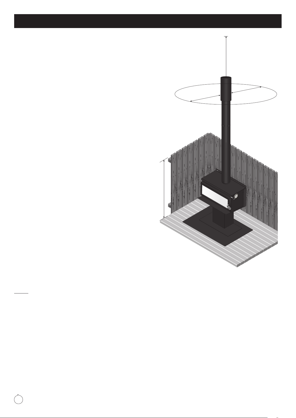
Once installed all minimum clearances and floor protection dimensions
must be adhered to. This includes the critical clearances vertically and the
clearance radius of the flue system termination.
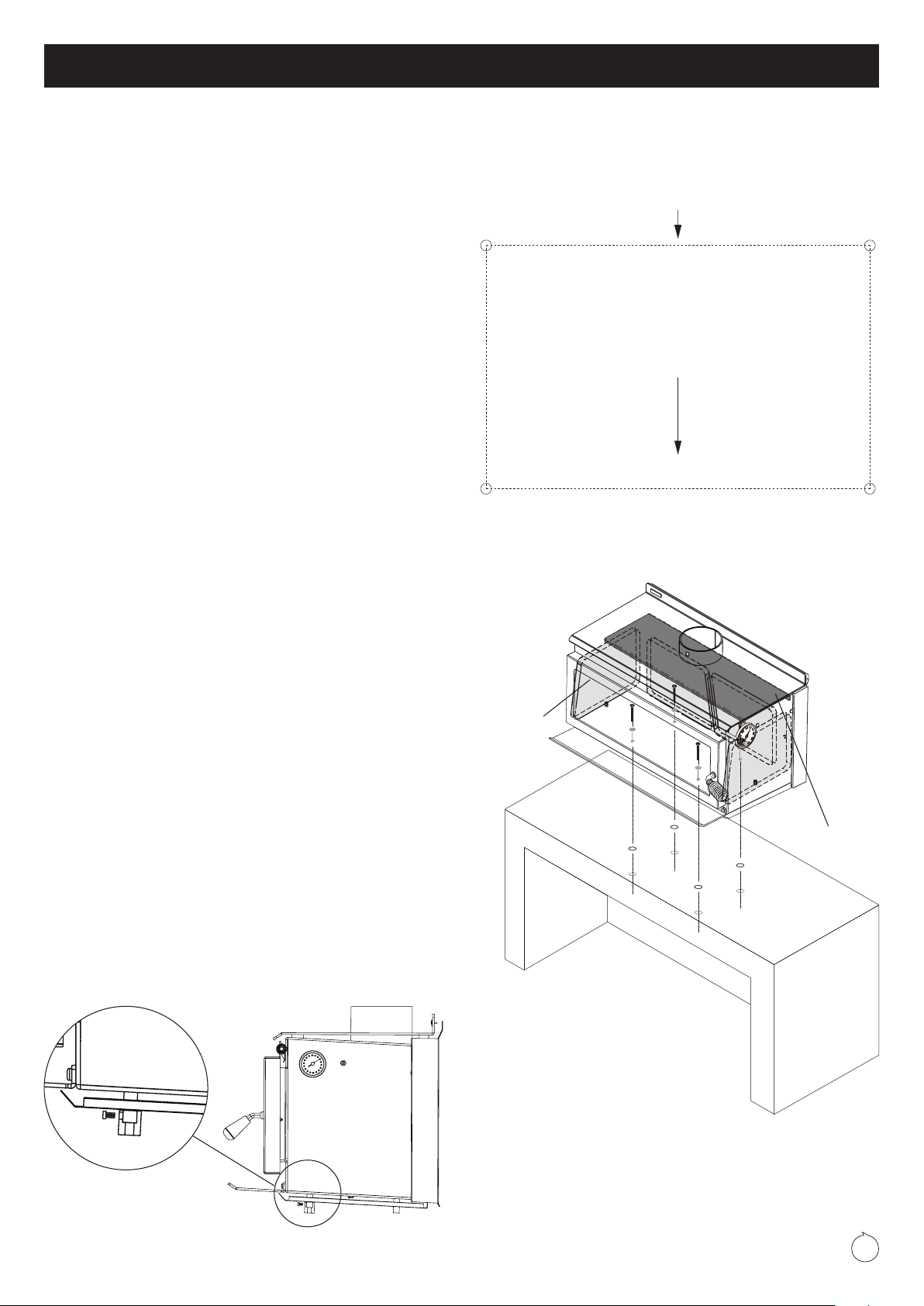
Floor protector positioning
Your Outdoor 850 Floor Protector has two sets of fixing points
pre-drilled for the seismic restraint of the Outdoor 850-P.
Using the most forward set of fixing points will require you to position
your Pioneer floor protector a minimum of 106mm from the nearest rear
combustible wall/fence. This will ensure the minimum rear clearance of
150mm to the fire is achieved once your Outdoor 850-P is installed.
Using the rear set of fixing points will require you to position your Pioneer
floor protector a minimum of 266mm from the nearest rear combustible
wall/fence. This will ensure the minimum rear clearance of 150mm to the
fire is achieved once the Outdoor 850-P is installed.
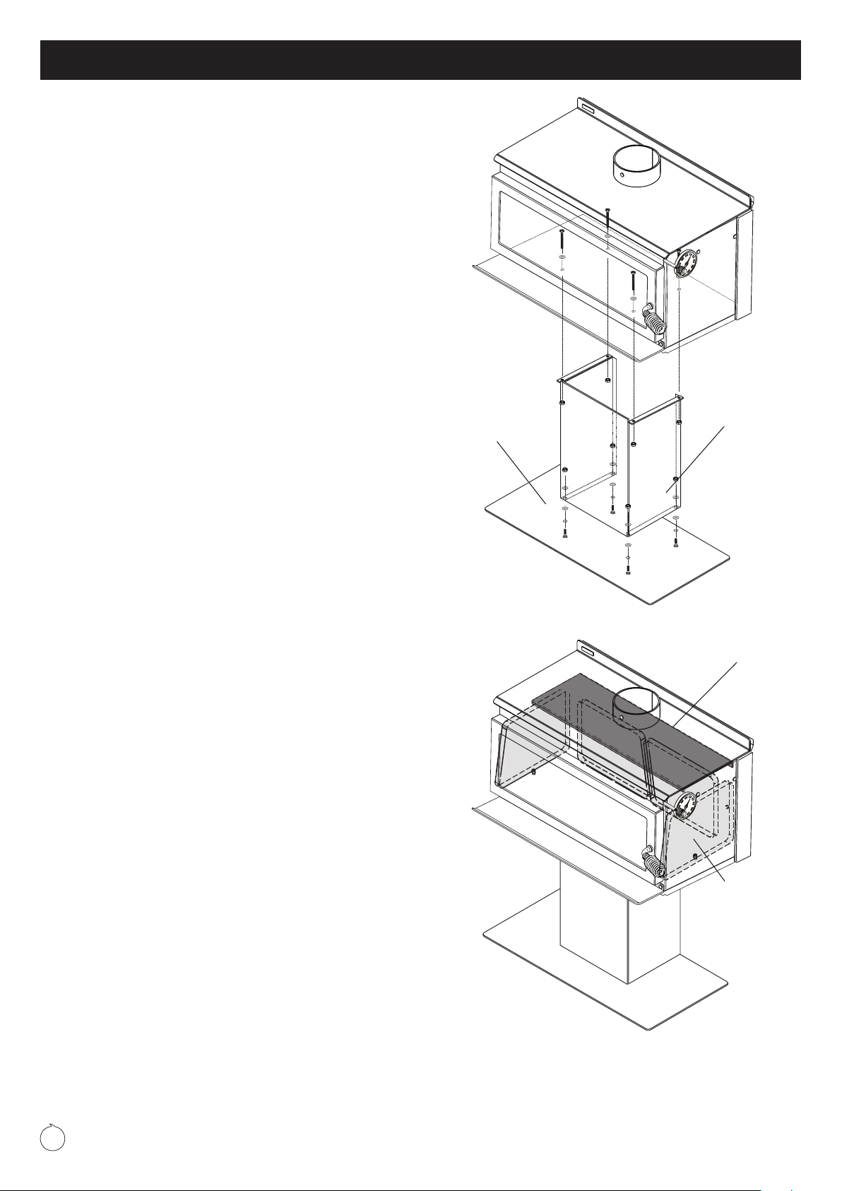
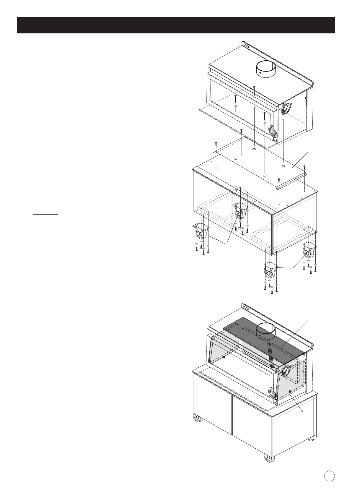
Floor protector installation
Move the Outdoor 850 fire onto the floor protector and using a suitable
measuring device, ensure that the minimum wall clearances and front
floor protector projections as detailed in the chart on page 6 are met or
exceeded. Once the fires location on the floor protector is established,
seismic restraint is required. Using masonry anchors if the floor protector
is on a concrete floor or coach bolts if a wooden floor, secure the Outdoor
850-P through the holes provided in the base plate, at each side of the
pedestal leg. The Outdoor 850-T must have the braked castors locked.
Note: The anchors must pass through the floor protector and securely
anchor the Outdoor 850-P fire to the floor.
Floor protector size, construction and fitting
Your Outdoor 850 comes complete with a cooking tool kit and a stainless steel
hanging bracket for hanging your cooking tools. Packed under the fire’s ashlip
are your cooking tool kit aluminium handles and the stainless steel tool ends
are packaged inside the firebox. Assemble your tools using the 4mm Allen
key supplied with the firebox. Please remove all plastic film where applicable.
Your cooking tool kit includes: 1x grill lifter, 1x fire rake and 1x pizza peel.
Assembly of the Grill Lifter tool (A)
Insert the stainless-steel removal tool end into the aluminum extruded handle,
this is the second longest handle (835mm). Line up the holes and use the 4x
M6x8mm stainless dome head socket screws with washer’s (1 washer under
each bolt head). Insert bolts and tighten.
Assembly of the Fire Rake (B)
Use 2x M6x12mm dome head socket screws and two flat washers one under
each bolt head. Attach the fire rake end to the shortest aluminum handle
(810mm). The handle has two threads inserted at one end so nuts are not
required. The return fold of the fire rake end goes towards the front of the
handle.
Assembly of the Pizza Peel (C)
Use 2x M6x12mm dome head socket screws and two flat washers, one under
each bolt head. Attach the pizza peel end to the longest aluminum handle
(920mm). This handle has two threads inserted at one end so nuts are not
required. You will notice the handle end has an angle cut that matches the
angled profile of the pizza peel end.
Cooking Tool Kit - Tool assembly instructions
(A)
(B)
(C)

11
The Outdoor 850 fires are for outdoor use only and cannot be installed
inside your home. Confirm with your local building authority or Metro
stockist for the outdoor fire regulations in your local area.
Your Outdoor fire must be located on a non combustible, stable, level
surface and secured by fixing points located in the pedestal base plate or by
locking the braked castors on the trolley once the fire is in place.
The Outdoor 850B model must be installed on a non combustible plinth/
bench which meets the requirements of AS/NZS2918. The 850B must be
fixed through the firebox into the plinth/bench using the Outdoor levelling
feet provided.
External structures and the proximity of other buildings will differ for every
installation and some situations will require additional flue height to comply.
Your Metro retailer will be able to advise if you are uncertain on the best
location for installing your Outdoor 850 fire.
• WE HIGHLY RECOMMEND YOU READ THIS ENTIRE
MANUAL AS INCORRECT OPERATION, MISUSE AND/OR
LACK OF MAINTENANCE WILL VOID THE WARRANTY
• Do not use flammable liquids or aerosols in the vicinity of this
appliance when it is operating
• Do not dry clothes on or near this appliance
• Do not use flammable liquids or aerosols to start or rekindle the fire
OR store fuel within the Metro’s specified installation clearances
•
Never operate your Metro with the door ajar, except on initial start up
• Open the air control fully before opening the Metro’s door
• This appliance is designed to burn clean/dry wood only.
WARNING! Important Information
• This appliance should be maintained & operated at all times in
accordance with this instruction manual
• This appliance should not be operated with cracked door glass, over
worn, faulty or missing door seals
• Do not use driftwood, treated or unseasoned (wet) fuel, the use of
most types of preservative treated wood as fuel can be hazardous
and will damage your appliance
• This appliance must be regularly maintained and replacement parts
must be authorised Metro parts only
• Do not empty ash into a combustible container.
This slow combustion outdoor appliance is designed to give you many years
of warmth and enjoyment, subject to the following key factors. These key
factors, if not adhered to are the major causes of unsafe installation, poor
performance and flue blockages and potential product failure.
1. Your Outdoor 850 wood fire must be installed and operated correctly.
2. The only fuel to be used in this appliance shall be wood that meets the
following criteria.
– Less than 25% moisture content
– Has not been treated with preservatives or impregnated with
chemicals or glue,
– Is not chipboard, particle board, or laminated board,
– Is not painted, stained or oiled
– Is not driftwood or other salt impregnated wood
3. The appliance shall be operated at all times in accordance with the
“Installation and Operating Instructions” supplied with each appliance.
4. Coal must not be used as a fuel.
Please also note the following important points:
•
During the very first fire your Outdoor 850 will give off an odour and
fumes as the firebox paint cures. Do not be alarmed; this curing process
will last for approximately one hour and is likely to happen this one time
•
Properly seasoned (dry) timber is necessary for the Outdoor 850 to
operate efficiently; firewood that contains a high moisture content will
result in flue pipe blockages, reduce heat output and create other issues.
Note: Once split, Softwood usually takes 12 months to season - Hardwood
can take up to 24 months to season - Wood must be stored in a location
that enables air circulation. Unseasoned wood stored in a closed woodshed
without air circulation will still be unseasoned 12 months later.
• It is critical that the fire not be operated with over worn, faulty or missing
door seals. Door seals will harden over time and become over-worn and
will cause air to leak into the fire, causing the appliance to ‘over fire’
• It is critical that the fire not be operated with over worn, faulty or missing
bricks, baffle plate or burn tray
• It is critical that the fire not be operated with cracked or broken door
glass.
Please note, the above 3 points require regular inspection/maintenance
(every time the burn tray is cleaned out) and if not maintained will void the
firebox warranty. A glowing firebox or fluepipe parts is just one sign you are
over firing your appliance. Please ensure you keep your proof of purchase/
receipt on any parts you purchase.
• For optimum performance fuel must be loaded so the logs lay “front
to rear” in preference to laying across the width of the firebox. Spaces
should be left between the logs to enable oxygen to get to as much of
the surface of the fuel as possible
• Your Outdoor 850 is covered by a full unconditional 12 month warranty
on replacement parts, and a 3 year firebox warranty.
Congratulations on the purchase of your Outdoor 850 wood fire
CAUTION! Important Information
Where to install your Outdoor 850 wood fire

12
During the very first fire your Outdoor 850 will give off an odour and fumes
as the firebox paint cures. Do not be alarmed. This curing process will last
for approximately one hour and is likely
to happen this one time.
Operating your Outdoor 850
Operating your Outdoor 850 fire is
simple and you will quickly learn how to
get the best from it. First take a minute
to familiarise yourself with your new
Outdoor fire.
• Raise the door handle anti-clockwise until the latch releases, and then
slowly pull the door open.
• There is a single air control making your Outdoor 850 easy to adjust.
This control moves from left to right, which is ‘low to high’. Simply pull
out to increase burn rate or push in to reduce burn rate.
Start up
Place a generous quantity of loosely crumpled newspaper on the base of
the firebox until it is approximately half full of paper, and place firelighters
on the base of the firebox if you wish. Add dry kindling and move the air
control knob fully to the right, being the ‘full open’ position.
Light the paper at two or three locations across the front of the door
opening and leave the door slightly ajar resting on the latch pin if necessary
for a few minutes while the fire establishes. Once the kindling is burning
well, open the door and add 2-3 small logs at a time until you have a well-
established fire. Usually this will take approximately 30 minutes, during
which time the air control should be set on “high” and the door should be
closed, except for the initial few minutes and when fuel is being added.
Normal operation
Once the fire is well established, regulate the air control to achieve the
desired burn rate and heat output. As you move the air control to the right,
burn rate, firebox temperature and heat output will increase, if you move
the control to the left they will decrease. Please note:
• Always open the air control fully prior to opening the door, then open
the door slowly. Every time you refuel, leave the air control on ‘high’ for
a minimum of 10-15 minutes
• When loading logs, place them end-on, ‘front to back’; air spaces
should be left between the logs to enable oxygen to get to as much of
the surface of the fuel as possible
• Never use the door to force wood into the firebox, as this is likely to
break the glass.
Cooking
Your Outdoor 850 gives you the opportunity to enjoy the full experience of
a flame grilled steak or the delicious taste of wood fired pizza. Designed
for cooking a range of foods both inside the fire and on top, your Outdoor
850 will also boil a flat bottom stainless steel kettle. The expansive cooktop
enables pots, pans and the Outdoor Oven to be placed on top for cooking.
Use of the Outdoor trivet is recommended.
Cooking grill / pizza stone
Prior to using the cooking grill, please insert the 5th Metro firebrick into the
cradle under the grill. This helps regulate the temperature during cooking.
Once the fire has burnt down to a good bed of embers, the cooking grill
(with or without the pizza stone) can be lifted into the fire using the grill
lifter tool. We recommend placing the cooking grill to the right hand side of
the firebox for ease of use and access during operation.
Your cooking grill needs to be seated corrected in the firebox before use.
Ensure you locate the cooking grill so the two vertical return folds at the
rear of the grill locate over the lip of the channel running along the rear wall
of the firebox.
You can cook directly on the cooking grill, or slide in the pizza stone and
turn your Outdoor 850 into a pizza oven to enjoy delicious wood fire pizzas.
Pre-heat the pizza stone for a few minutes before cooking on it.
Once you’ve finished cooking, you can remove the cooking grill using the
grill lifter tool. Please ensure you take care when removing the hot cooking
grill from the fire and place it onto a non combustible surface well out of
harms way.
Operating your Outdoor 850 wood fire
• All surfaces will get very hot. Do not touch or place combustible
components on or against your appliance
• Be aware of small children and impaired persons around your
appliance when in operation. We recommend you install a child
guard around your appliance for adequate safety.
• Please run your cooking grill through a heating cycle before
using for cooking.
WARNING! Important Information
Outdoor fires air control
LOW
HIGH
Cleaning and maintenance for your Outdoor 850 wood fire
Your Outdoor 850 fire will give you many years of efficient service with
minimal maintenance if operated correctly using seasoned fuel. Your
Outdoor 850 must be regularly maintained and replacement parts must be
authorised Metro fires parts only.
The Outdoor 850 fires are painted and finished with ‘Pioneer Zinc Black’
high temperature paint formulated for outdoor use to provide a high level
of corrosion resistance. Outdoor 850 fires will require periodic repainting to
keep them looking their best. All models can be cleaned with a soft cloth
when the appliance is not in operation.
Door glass
Providing your fuel is properly seasoned, under normal operating
conditions the air-wash design of the Outdoor 850’s firebox will keep the
door glass clear. If the glass requires cleaning you may use either a razor
blade scraper or crumpled wetted newspaper dipped in wood ash rubbed
over the glass.
If your door glass breaks it must be replaced with 4mm thick ceramic glass
which is available from your local Metro retailer.

13
Door seals
Over time, usually 3-4 years, the door and glass seals will become hard and
cause air to leak into the firebox, causing the appliance to ‘over fire’. Your
Metro retailer stocks replacement woven ø15mm fibreglass door and glass
seals, which need replacing when they become hard and over worn.
The door of your Outdoor 850 is easily removed. Hold it in both hands and
lift the hinge end of the door up and over the top hinge pin, then lower the
door from the bottom hinge pin.
We recommend you reapply high temperature anti seize to the door lug as
necessary to improve door opening/closing.
Fire bricks
Hair-line cracks are not uncommon and are a result of the intense heat
within the Outdoor 850’s firebox, coupled with mechanical damage caused
by accidental impact when fuel is being loaded. However if the fire bricks
become cracked to the extent that they start to break up and fall away, they
must be replaced.
Door adjustment
Provision is available on both sides of the door for adjustment.
To adjust the hinge end of the door, open the door fully, loosen the top hinge
nut and slightly lift the latch end of the door; you will see the hinge assembly
move back 1-2mm which will usually be sufficient. Retighten, then repeat
by loosening the lower hinge nut, this time applying a slight downwards
pressure onto the door to move the lower hinge assembly back a similar
distance, then retighten.
The door latch is also adjustable, as the latch pin on the right side of the
firebox is fitted through a slot which enables the latch pin to be loosened,
moved back and re-tightened.
Ash removal
Depending on the amount of use, over a period of time ash will build up in
the burn tray of the Outdoor 850’s firebox and require removal. The time
this build-up takes depends on the density and cleanliness of your fuel.
To remove the excess ash your fire should not be operating.
• Open the door, and using a hearth shovel or similar, empty the excess
ash directly into a steel or non-combustible container
• If the ash is not disposed of immediately, be careful where you store it,
as the ash can retain heat for many days and become a fire hazard
• You must leave a bed of ash in the base of the burn tray approximately
10mm deep; this insulates the base of the firebox and improves next
start-up and combustion.
• The burn tray is easily removed by lifting at the tray lugs both left and
right front of the burn tray.
Top baffle
This is a ‘sacrificial’ wear part of the firebox and should be checked monthly.
Ensure you replace the top baffle once fully deteriorated
Flue system
The flue pipe should also be swept a minimum of once a year, or as required
depending on amount of use and noticeable deposits. If excessive smoke
exits the firebox when you open the fire’s door this usually indicates the flue
pipe is becoming restricted and needs cleaning. The frequency of flue pipe
cleans depends on many factors, with the main variables being:
• The seasoning of the wood. If not properly seasoned you will require
frequent flue pipe cleans
• The density of the wood. Softwoods generally result in more deposits
building up in the flue pipe.
To clean the flue pipe of your Outdoor 850, proceed as follows:-
• Open the fires door fully, reach inside with both palms of your hands
face-up and extended, lift the top baffle approximately 20mm, then
lift it forward out through the door opening, placing it on a sheet of
newspaper you have placed on the front of the floor protector. To
prevent jamming, removal and replacement of the top baffle is best
performed using both hands. We recommend carefully removing the
side bricks before removing/replacing the top baffle
• Close the door and slide the air control to the left
• Using a ladder, remove the cowl from the top of flue system and sweep
the flue pipe using a 150mm-diameter flue pipe brush as detailed in the
instructions provided with the fluebrush
• Once the flue pipe is clear, clean and refit the cowl. Remove the excess
soot which has fallen into the firebox, leaving a layer of ash 10mm deep
in the burn tray, then refit the top baffle.
Note: The baffle must be fitted so its rear is touching the back of the firebox;
if uncertain refer to pages 3-5 in the installation section at the front of this
manual, which shows illustrations of the baffle location.
Surface Renovations
Your appliance is made from Corten steel and stainless steel. The high
temperature paint finish is zinc based. All these attributes contribute to
extending the life of your Outdoor 850 fire.
To maintain the cosmetic appearance you will need to regularly maintain
the surface. The extent of necessary maintenance will be determined by
the time between renovations, length of time the appliance remains outside,
any unintended mechanical damage and the vicinity of salt laden air to the
appliance.
You can easily prepare the surface of the corten prior to repainting by either
sanding or using a mild anti-oxidisation agent to remove surface rust or
staining
You can purchase high temperature aerosol black zinc paint from your
Metro retailer for this renovation. The appliance is coated in Pioneer Zinc
Black high temperature paint and the flue system in Pioneer Satin Black
high temperature paint.
Cleaning and maintenance for your Outdoor 850 wood fire

14
If your Outdoor 850 is installed correctly, your fuel is dry and you operate
your fire correctly, you will find it to be a pleasure to use. Metro’s many
years of experience within the wood heating industry has shown that
dissatisfaction is mainly due to:
• unseasoned fuel
• faulty installation
• operational error
• or a combination of the above 3 points.
Correct operation
Your Outdoor 850 fire needs to be operated hard and fast, more so than
low and lazy to ensure the firebox and flue pipe runs hot and efficiently. If
the fire and flue pipe is up to temperature it will perform extremely well, the
smoke will draw up the flue pipe with ease, and the fire will produce good
amounts of heat.
If the fire is operated on low a lot of the time, the door glass will run black,
the flue pipe will tend to block up more frequently and you may experience
excessive smoke exiting the firebox when reloading fuel. It’s better to have a
small fire running hard and fast, rather than a big fire running low and lazy.
The following may be of assistance if you are experiencing any problems
with the operation of your Outdoor Metro.
Smoke exits the fire when the Outdoor 850’s door is ajar
If you are burning unseasoned fuel (wet), the fire will cause nothing but
problems. Your Outdoor 850 won’t deliver much heat, it will be lazy, smoke
will exit the fire when the door is ajar, and the door glass will run black.
Unseasoned fuel is the main contributor to excessive soot deposits which
can be corrosive to both your appliance and flue system.
Downdraft/Turbulence blockage
If you have checked all of the previous factors and you’re still experiencing
excessive smoke exiting the firebox when reloading fuel, it’s possible there
may be a down draft issue. Down draft is environmental and can be caused
by many variables, and it is purely trial and error to ascertain the cause.
Air turbulence and/or negative air pressure influences around the flue
termination can be caused by too close or overhanging trees or natural/
artificial walls etc.
Air control setting
Ensure the air control setting is on high before opening the door to reload,
as this increases the draw up the flue pipe. Open the door slowly.
If your fire did not smoke, but its starting too and is getting worse:
The flue pipe is in need of a clean. It is recommended that the flue pipe be
cleaned every season, however if you are burning the fire on low a lot, or are
using unseasoned fuel, flue pipe cleans will be required more frequently.
The fire is noisy as it heats up and cools down
There will always be some expansion and contraction noise as your Outdoor
850 heats and cools. This is normal.
Troubleshooting your Outdoor 850 wood fire
Your Outdoor 850 fire must be regularly maintained and we recommended
it is also serviced annually. If a wood fire is not regularly maintained and
serviced, the life span will be reduced.
If your Outdoor 850 fire has been neglected, by not being regularly
maintained and serviced, with authorised Metro parts replaced as required,
any warranty may be declined.
The burn tray is designed as a sacrificial base inside the firebox and will
deteriorate over time. It must be used when the fire is in operation. Once it
deteriorates to the point where it can no longer contain ash and/or embers
(e.g has holes burnt through it) it must be replaced.
Listed below are the parts and product codes for your Outdoor 850 fire. The
baffle should be regularly checked and must always be in place during the
operation of your fire.
The baffle should be resting on four support lugs (two on each side of the
firebox). It must be hard back against the rear of the firebox with the return
front steel edge of the baffle facing forward. If uncertain refer to pages 3-5 in
the installation section at the front of this manual, which shows illustrations of
the baffle location.
Product code Description Product code Description
500-3050 Top baffle 560-0100 Burn tray
500-1100 Side/Rear firebrick 500-0756 Door rope seal
560-0070 Pizza stone 500-0855 Door glass seal
9052-0050 Temperature gauge 500-0630 Door glass retainer
560-0080 BBQ/Cooking grill 500-0270 Door glass
Parts guide for your Outdoor 850 fire

15
Warranty details for your Outdoor 850 wood fire
Outdoor by Metro fires are manufactured in New Zealand, using the highest
quality of materials, workmanship and the latest manufacturing techniques,
which is why we offer a full 3 year firebox warranty and a 12 month parts
warranty for your peace of mind.
Metro Warranty
(NZ Consumer laws apply to this warranty)
Pioneer Manufacturing Limited (Pioneer) warrants the corten steel firebox
against defective materials and workmanship which would render it unfit for
normal domestic use, from the date of purchase by the original consumer,
for a period of 3 years.
Components including flue systems, door retainers, door seals, glass,
baffle and bricks are warranted for a period of 12 months from the date of
original purchase for normal domestic use against defective materials and
workmanship.
Please ensure you retain your proof of purchase/receipt for the appliance
and any parts you purchase.
The Outdoor pizza stone is not covered under warranty.
Warranty Conditions
• The Outdoor 850 fire must be installed, operated and maintained strictly
in accordance with this installation and operation manual
• The Outdoor 850 fire must be installed and used in a domestic outdoor
application
• This warranty covers appliance like for like replacement or repair at the
manufacturer’s discretion but excludes freight, travel, installation, labour
and/or any other associated costs
• Pioneer or their agents are not liable for any loss or expense direct or
indirect arising from the failure of any part or operation of the appliance
• Operation of this appliance in violation of the warnings in this operation
and installation manual will void this warranty
• Your Outdoor 850 fire must be regularly maintained and we
recommended it is also serviced annually. Proof of servicing may be
required. If a wood fire is not regularly maintained and serviced, the life
span will be reduced. If your Outdoor 850 fire has been neglected, by
not being regularly maintained and serviced, warranty may be declined
• It is critical the fire not be operated with over worn, faulty or missing
door seals. Door seals will harden over time and become over-worn
causing air to leak into the fire, causing the appliance to ‘over fire’.
Do not operate the fire with cracked, or broken door glass
• It is critical the fire not be operated with over worn, faulty or missing
bricks, baffle plate or burn tray
• A claim under this warranty should be directed to the retailer who
supplied the Outdoor 850 fire. If this is not possible write directly to the
manufacturer stating details of fault, model, dated proof of purchase
and name of retailer purchased from.
Warranty Exclusions
(This manufacturer’s warranty does not cover)
• Service calls which are not related to any defect in the product (i.e.
operational, installation or fuel issues). The cost of a service call will be
charged if the problem is not found to be a product fault
• Defects caused by factors other than normal domestic use or use in
accordance with the product’s operation manual
• Defects caused through the product being operated in an ‘over-fired’
manner resulting in sections of the firebox operating excessively hot to
the point that sections glow red. (Note – This will result in distortion of
the firebox)
•
Defects to the product caused by accident, neglect, misuse or act of God
• The cost of repairs carried out by non-authorised repairers or the cost of
correcting such unauthorised repairs
• Required maintenance as set out in this manual.
Service under this manufacturer’s warranty must be provided by a repairer
authorised by Pioneer Manufacturing Ltd. Such service shall be provided
during normal business hours.
Purchase Date
Model
Retailer
IMPORTANT! Complete and retain these details at time of purchase:

Pioneer/Metro Fires offer a range of heating accessories designed to
compliment your Outdoor 850 fire. See below for some of the products
within our heating accessory range. The range of accessories includes floor
protectors, cooking implements, baffles, bricks and more. For further details
ask your Metro retailer for a copy of the Outdoor by Metro brochure, or visit
www.metrofires.co.nz
metrofires.co.nz
Visit the Metro website www.metrofires.co.nz to view Metro’s ‘video demos’
showing the latest in wood fire technology and energy saving options. You
can view the entire Metro product range, find out where your nearest Metro
retailer is located or simply check out the latest specifications, installation
requirements and emission and efficiency data for the Metro of your choice.
Cooking grill (included with fire) Pizza Stone (included with fire)
Cast iron trivet
Paint aerosols
Cooking tool kit (included with fire)
Fire mitts
Replacement firebricks 850 Accessory Pack
Metro - Visit us online today www.metrofires.co.nz
Outdoor by Metro accessories
16
Wooden pizza paddle
Pizza cutter All weather cover
Steel floor protector
This manual suits for next models
3
Table of contents
Other Metro DataVac Outdoor Fireplace manuals
Popular Outdoor Fireplace manuals by other brands

Coleman
Coleman 5062-710 Assembly and instruction sheet

QOMOTOP
QOMOTOP QTFP02 Assembly instructions

Essential Garden
Essential Garden JFP-008 owner's manual

Signature Design by Ashley
Signature Design by Ashley P456-776B user guide

Outdoor GreatRoom Company
Outdoor GreatRoom Company Crystal Fire CV-30WT installation instructions

Blumfeldt
Blumfeldt 10030244 quick guide