9SHK 200S
SHK 200S-6
4 Pipe connections
General pipe connections
Pipe installation must be carried out in accordance
with current norms and directives.
The pipe dimension should not be less than the recom-
mended pipe diameter according to the table below.
However, each system must be dimensioned individu-
ally to achieve the recommended system ows.
The system can cooperate with a low- and medium
temperature heating system. Recommended temper-
ature of the heating medium at minimum designed
outdoor temperature DOT must not exceed 55°C on
supply, and 45 °C on return circuit from the heating
system, whereas HK 200S / HK 200S-6 can achieve
even 65 °C when using a ow-through heating mod-
ule or another peak heat source.
Excess medium owing out of the safety valve must
be discharged via a pipe to a oor drain. The over-
ow pipe must be slanted at the entire length from the
safety valve, and must be secured against freezing.
In order to achieve maximum system efciency, we
recommend the installation of HK 200S / HK 200S-6
as close to the heat pump as possible.
The HK 200S / HK 200S-6 module is not equipped with
cut-off valves, which must be installed outside the in-
door module to make future maintenance easier.
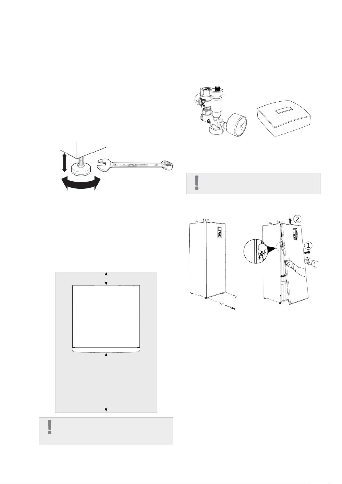
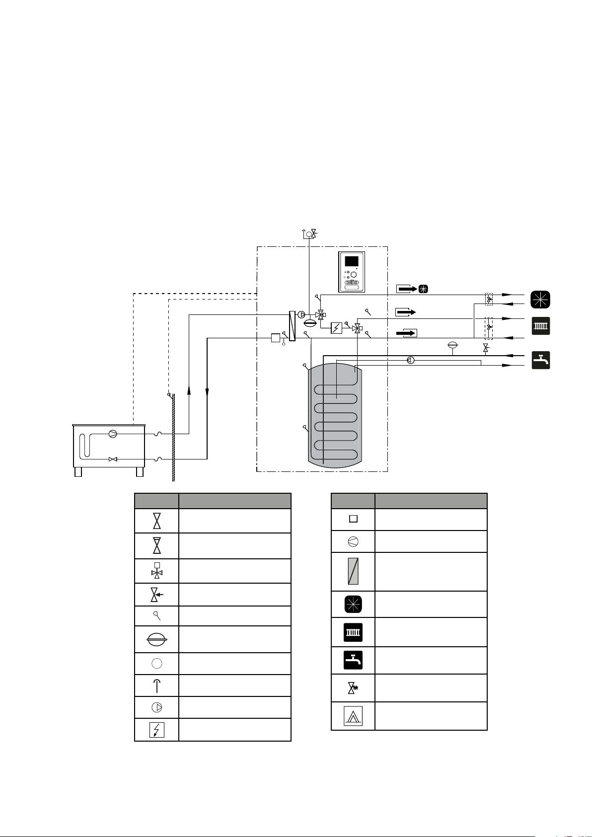
The HK 200S / HK 200S-6 module can be connected
to the central heating, cooling, and domestic hot wa-
ter installation. Install the supplied safety valve and
the manometer.
Air/water
heat pump
Minimum
ow during
defrosting
(100%
pump
speed (l/s)
Minimum
recom-
mended
pipe
dimension
(DN)
Minimum
recom-
mended
pipe
dimension
(mm)
SHK 200S-6 / L6 0,19 20 22
SHK 200S / L8 0,19 20 22
SHK 200S /
L12 0,29 20 22
IMPORTANT
Any high points in the climate system, must be
equipped with air vents.
IMPORTANT
The pipe systems need to be ushed out before
the indoor module is connected so that
any debris cannot damage component parts.
IMPORTANT
As long as heating circuits in the system have not been
lled with the heating medium, do not set the switch
(SF1) in the controller in position “I” or “ ”. The com-
pressor in the heat pump and the ow-through heating
module can be damaged.
MINIMUM SYSTEM FLOWS
The installation must be dimensioned at least to man-
age the minimum defrosting ow at 100% pump op-
eration, see table.
IMPORTANT
All connections require free ow, hence a discharge
valve must be installed.
IMPORTANT
An undersized system can result in damage to the
machine and lead to malfunctions.
Chapter 4 | Pipe connections
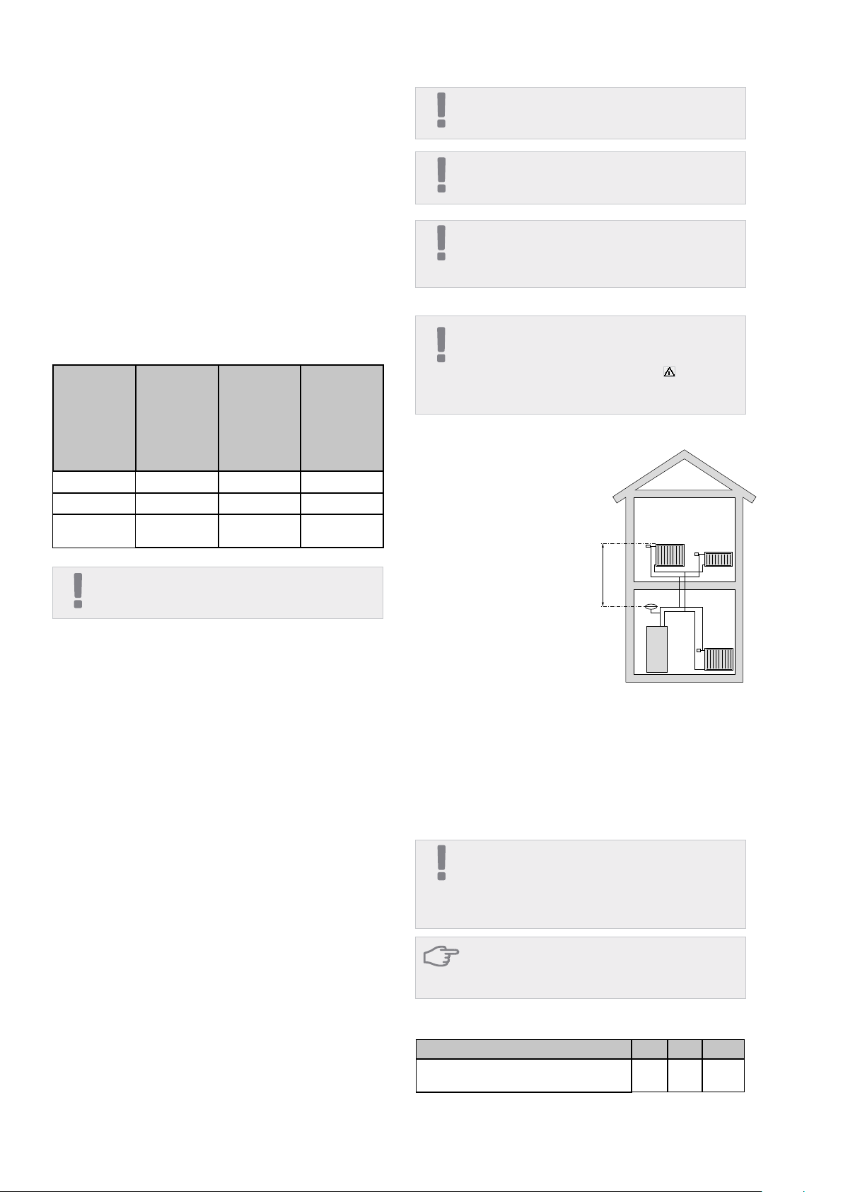
SHK 200S / SHK 200S-6
is equipped with a pres-
sure expansion vessel of
10 litres. The pre-pres-
sure of the pressure ex-
pansion vessel must be
dimensioned according to
the maximum height (H)
between the vessel and
the highest positioned
radiator, see gure. A
pre-pressure of 0.5 bar (5
mvp) means a maximum
permitted height differ-
Expansion vessel
Volume expansion
Minimum volume of the heating system
CAUTION
The diaphragm expansion vessel at the domestic hot
water installation is not required. It is, however, required
to install a safety valve with opening pressure of 3 bar.
ence of 5 m. The maximum system volume excluding
the boiler is 220 litres at the above pre-pressure.
Approx. 10 l/kW is required for connection to the heat
pump, and many heating systems do not have this
volume. To prevent operational problems, the volume
is then expanded using a UKV buffer vessel.
METROAIR L 6 8 12
Minimum volume of the heating system
during heating / cooling 50l 80l 100l
IMPORTANT
In order to achieve undisturbed ow of the heating sys-
tem, use a hydraulic coupling or open heating loops.
Remember to always keep the minimum required ow
in the installation - see the section "Minimal ow in the
installation".