metrofires Bay User manual

Metro Pellet Fires
INSTALLATION &
OPERATION MANUAL
Safety First.............................................................................Page 3
Installation Clearances ......................................................Page 4
Installation Configurations................................................Page 6
Installation Vent Systems ..................................................Page 7
Operation................................................................................Page 9
MX3™ Controller ...............................................................Page 10
Maintenance & Cleaning ..................................................Page 12
Troubleshooting .................................................................Page 15
Diagram & Parts List.........................................................Page 18
Warranty ..............................................................................Page 20
Bay & Bay Insert Models
PRINTED MARCH 09

2
TABLE OF CONTENTS
SAFETY FIRST ................................................................................................................................................... 3
INSTALLATION
• Clearance to Combustibles.................................................................................................................................. 4
• Installation Clearances........................................................................................................................................ 4
• Electrical Requirements ..................................................................................................................................... 5
• Fuel Requirements .............................................................................................................................................. 5
• Fuel Storage......................................................................................................................................................... 5
• Location of the Pellet Fire.................................................................................................................................... 6
• Typical Installation Congurations...................................................................................................................... 6
• Venting System .................................................................................................................................................... 7
METRO PELLET INSERT ADDITIONAL CONSIDERATIONS
• Metro Pellet Insert Additional Requirements ..................................................................................................... 8
• Fascia Surround................................................................................................................................................... 8
• Metro Pellet Insert Installation............................................................................................................................ 8
• Metro Pellet Insert Removal................................................................................................................................ 9
• Operation and Maintenance................................................................................................................................. 9
OPERATION
• General Overview and Safety Features................................................................................................................ 9
• Electric Igniter ..................................................................................................................................................... 9
• Fueling the Hopper .............................................................................................................................................. 9
• MX3™ Control and Button Description.............................................................................................................. 10
• Wall Thermostat, Wall Switch or Other Switching Device................................................................................. 11
• Starting and Stopping Your Pellet Fire .............................................................................................................. 11
MAINTENANCE & CLEANING.................................................................................................................... 12
TROUBLE SHOOTING GUIDE ..................................................................................................................... 15
ADDITIONAL INFORMATION ...................................................................................................................... 17
DIAGRAMS AND PARTS LIST ..................................................................................................................... 18
WARRANTY INFORMATION ........................................................................................................................ 20

3
SAFETY FIRST
1. Read these instructions carefully. Failure to follow them could cause a malfunction of the pellet re,
damage to the pellet re or property damage.
2. Familiarize yourself with the pellet re’s operation. (See “Operation” section) If you are not sure, ask your
dealer for an explanation on your pellet re’s proper operation.
3. The burn pot of this pellet re is designed for premium grade wood pellets. Refer to the “Fuel
Requirements” section for more information.
4. Oiling the circulation fan motor bearings should be done every 12 months. See “Maintenance” section for
more details.
5. Check your local building codes regarding restrictions or installation requirements. All installations must
comply with local building codes.
6. Combustion of wood pellet fuel leaves ash in the pellet re and venting system. These ashes must be
removed from the pellet re regularly. See “Maintenance” section for more information.
7. This pellet re is POWER VENTED. The vent pipes are under positive pressure during operation. It is
IMPERATIVE that all joints in the venting system be SEALED to prevent any leakage of exhaust gases inside
the house. All joints must be sealed using high temperature silicone sealer (RTV). Aluminum tape is NOT
an adequate sealant.
8. Use of outside combustion air is highly recommended and is mandatory in mobile home installations.
9. This appliance is wired and grounded according to the electrical code AS/NZS/EN 60335.2.30 for New
Zealand.
10. Make sure the door and any other opening in the pellet re are closed tightly during operation. Inspect the
gaskets of the door and other openings periodically to make sure they are in good condition.
11. Replace broken or defective components only with parts provided by the manufacturer. Contact your local
dealer to nd out how to purchase replacement parts.
12. Follow this manual carefully for proper installation. If you are uncertain, call your dealer. Most dealers have
qualied and trained installers. We highly recommend the use of their services.
13. During the very rst re your Metro will give off an odour and fumes as the rebox paint cures. Do not be
alarmed; open all windows and externally opening doors in that room and close any internally opening
doors. This curing process will last for approximately one hour and will only happen this one time.
IMPORTANT MESSAGE
• THE PELLET STOVE MUST NOT BE LOCATED IMMEDIATELY BELOW A SOCKET-OUTLET.
• CAUTION: PELLET FIRE HAS MOVING PARTS. DISCONNECT POWER BEFORE SERVICING
• If you have any questions, comments or concerns regarding your new pellet re, please contact
your local dealer or Pioneer Manufacturing Ltd. at www.metrores.co.nz or 06 756 6520.
Please record the following information for future reference
Customer Name.............................................................................................................................................................
Installation address .......................................................................................................................................................
Phone Hm .................................................. Mobile...............................................Work............................................
Product Type (please tick) Freestanding Insert
Model ..................................................................................................................................................................
Retailer purchased from................................................................................................................................................
Retailer Address .......................................................................................................Date Purchased ..........................
Comments ..................................................................................................................................................................
..................................................................................................................................................................
4
INSTALLATION DETAILS
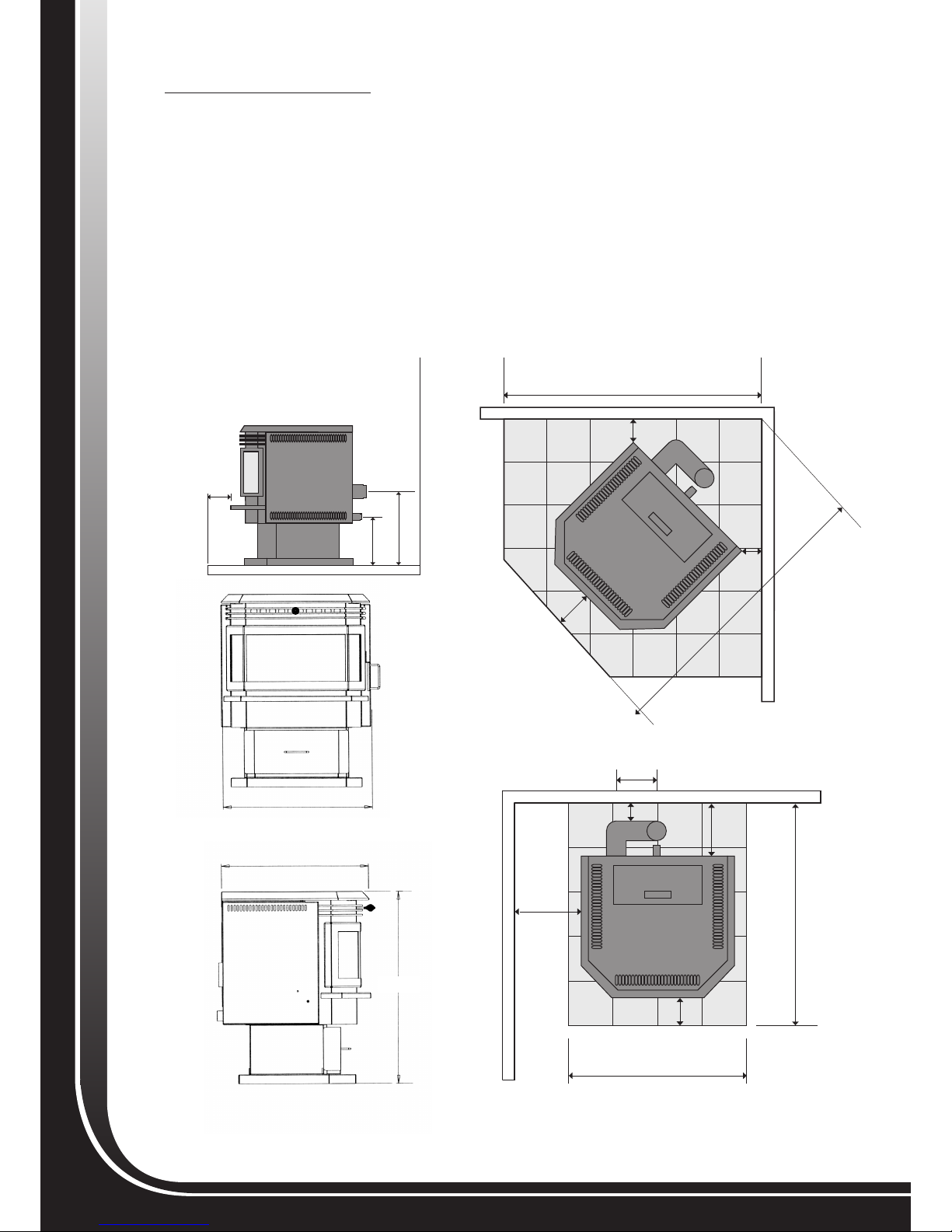
Clearance to Combustibles - Installation Clearances
Please refer to the following gures for all clearances to combustibles. Please note that these
clearances are for your METRO pellet re only.
Minimum clearances shown are in mm, and all gures for clearances are to combustible materials. All
Metro pellet res are tested using all applicable procedures and equipment under AS/NZS2918:2001.
We recommend sufcient space be provided (minimum 500mm) on each side of the pellet re to service
the unit. If this is not possible, provision must be made available to remove the unit for servicing.
Freestanding Dimensions
285mm
470mm
615mm
613mm
788mm
250mm
175mm
120mm
100mm
650mm
950mm
120mm
120mm
100mm
1000mm
1280mm
100mm
100mm

5
INSTALLATION DETAILS
Electrical Requirements
1. This pellet re is an electrical appliance. This appliance requires 230- 240 Volts, 50 Hz and 1.5-2.0 Amps of
electrical power.
2. The pellet re comes with a 1.5 M long, grounded, electrical cord suitable to plug into any standard residential
electrical outlet. The electrical outlet must be grounded.
Wood Pellet Fuel Requirements
Only approved wood pellets are to be used in this appliance which have been tested to and complies with AS/NZS
4014.6. Any other fuel used that does not comply with this standard will greatly affect the performance, operation
and the warranty of this appliance.
Wood pellets must not be:-
– Longer than 38mm
– Thicker than 10mm
– Have no more than 1% ne dust particles
If you nd your fuel has excessive amounts of nes and saw dust, the fuel should be screened before use. DO NOT
USE WET PELLETS under any circumstance. Longer fuel may cause bridging of the auger and result in erratic
feeding or jamming. Fines, binders, ash, moisture will all cause your pellet re to block up and not burn efciently.
“Poor” fuels require more frequent cleaning; the ashtray must be emptied and the burn pot must be cleaned on a
regular basis. Please refer to the “Maintenance” section for further instructions on cleaning your pellet re.
Fuel Storage
All pellet fuel should be stored in a clean dry place and at a safe distance (at least one metre) away from the re.
IMPORTANT MESSAGE
• THIS APPLIANCE SHALL NOT BE USED AS AN INCINERATOR. BURNING ANY FUEL OTHER
THAN WOOD PELLETS AS DESCRIBED ABOVE WILL VOID YOUR PELLET FIRE’S WARRANTY.
WARNING
618mm
614mm
533mm 485mm
356mm
Insert Dimensions
100mm
Figure 3: Minimum Fireplace opening for the
Metro pellet fire insert
410mm
500mm
560mm
1050mm
1020mm
300mm
531mm
100mm
381mm
NOTE: “If a timber mantelshelf exists above the pellet fire opening,
it should be a minimum of 452mm above the top of the pellet fire”
6
INSTALLATION DETAILS
Location of the Pellet Fire
When selecting a location for your new pellet re consider the following:
1. Clearance to combustibles. The pellet re must be installed with the proper clearances to combustibles to
protect against the risk of re.
2. Sufcient room to service the unit and size of the appliance. Allow yourself enough room to be able to service
the pellet re. Open the side panels and remove the back panel to see how much room you will need to access
the sides and the back comfortably. When installing the pellet re, please keep in mind that you will need to
clean the pellet vent system annually. If the pellet re must be placed in a tight area, make sure to conform to
the proper clearances to combustible materials and make sure you have enough room to disconnect the vent
system for servicing. Also, these appliances are heavy and may be awkward to move in order to service. The
free-standing pellet re weighs 92 kg and the insert pellet re weighs 70 kg.
3. Access for outside combustion air if required.
4. Power within 1.5m. The power cord is only 1.5m long. Make sure that your outlet is within 1.5m of the pellet re.
5. Access for exhaust venting.
6. The pellet re must not be located immediately below a socket-outlet.
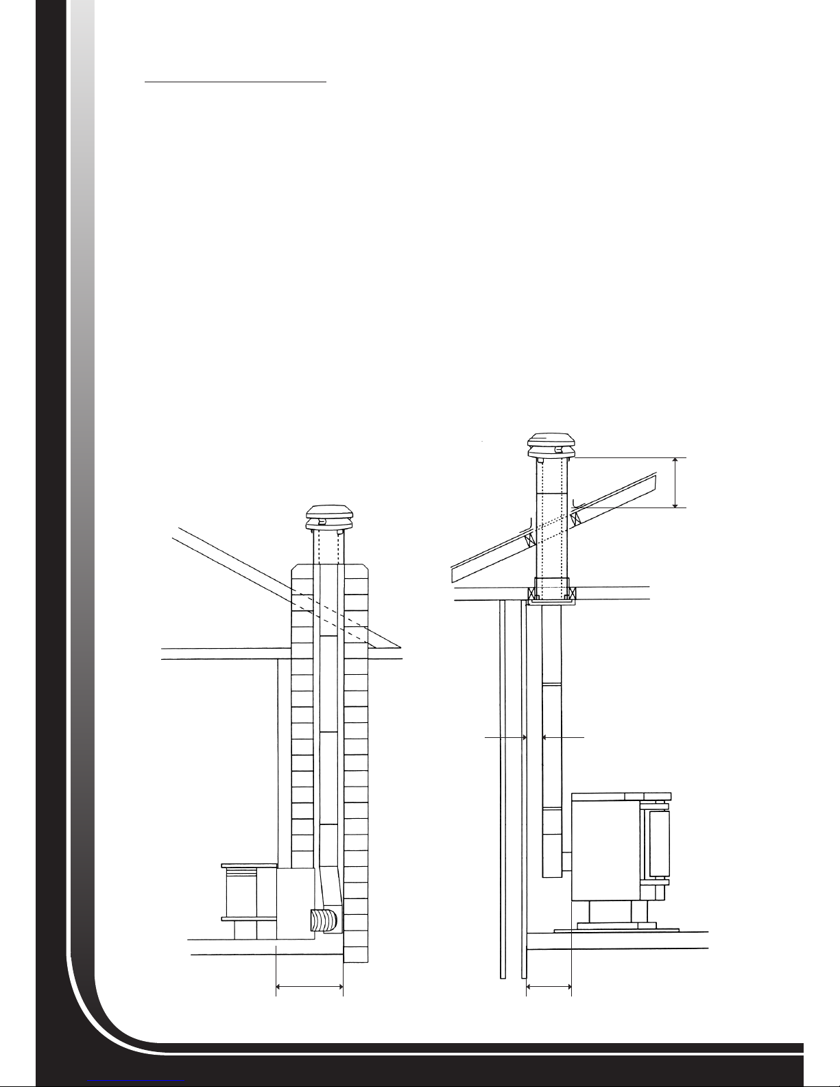
Typical Installation Configurations
The following gures illustrate some typical installations. Variations of these are possible. Common sense, safety
and compliance with local codes must be respected in any variation.
Figure1 Figure2
450mm
600mm
minimum
250mm
100mm
minimum

7
INSTALLATION DETAILS
Venting System
Your METRO pellet re works under negative pressure (vacuum). The exhaust fan of your pellet re pulls air from
the air intake, through the pellet re and pushes it out the vent system. Air passing through the burn pot is used to
burn the pellets. Proper vent pipe sizing is very important to ensure the pellet re operates properly. A proper size
approved venting should be used to provide the least resistance for movement of the combustion air.
The vent pipes on the exhaust side of the exhaust fan are under pressure. Care must be taken to ensure that all
the joints are completely sealed to prevent any leakage of exhaust fumes and smoke into the house. If you smell
smoke, the venting has not been properly sealed. Use only high temperature RTV silicone for sealing. Aluminum
tape is not considered an adequate sealant. At least 3 screws/or rivets are needed for securing all vent pipe joints.
The venting of this pellet re is not allowed to pass through any closets, concealed spaces, oors, ceilings or
attic spaces. If the venting must go through a wall or combustible partition, the installation must conform to the
Installation Code for Solid Fuel Burning Appliance and Equipment. For more detailed venting information, please
refer to your venting manufacturer’s instructions.
Combustion Air Intake Requirements
The Metro Bay has a direct vent option which when installed draws the combustion air from outside the home,
further improving the efciency of the pellet re. This is recommended as the Metro Bay can use up to 24 cubic
metres of room air every hour.
There are two methods of supplying the pellet re with combustion air. They are as follows;
• DV WALL KIT ducts through an outside wall
• DV FLOOR KIT ducts through the oor directly behind the Metro
IMPORTANT MESSAGE
• THE APPLIANCE AND FLUE-SYSTEM SHALL BE INSTALLED IN ACCORDANCE WITH AS/NZS
2918 AND THE APPROPRIATE REQUIREMENTS OF THE RELEVANT BUILDING CODE OR CODES.
• DO NOT USE MAKESHIFT MATERIALS OR MAKE COMPROMISES IN THE INSTALLATION. IT IS A
FIRE HAZARD.
• DO NOT INSTALL A FLUE DAMPER IN THE EXHAUST VENTING SYSTEM OF THIS PELLET FIRE.
• DO NOT CONNECT THIS PELLET FIRE TO A CHIMNEY FLUE SERVING ANOTHER APPLIANCE.
WARNING
8
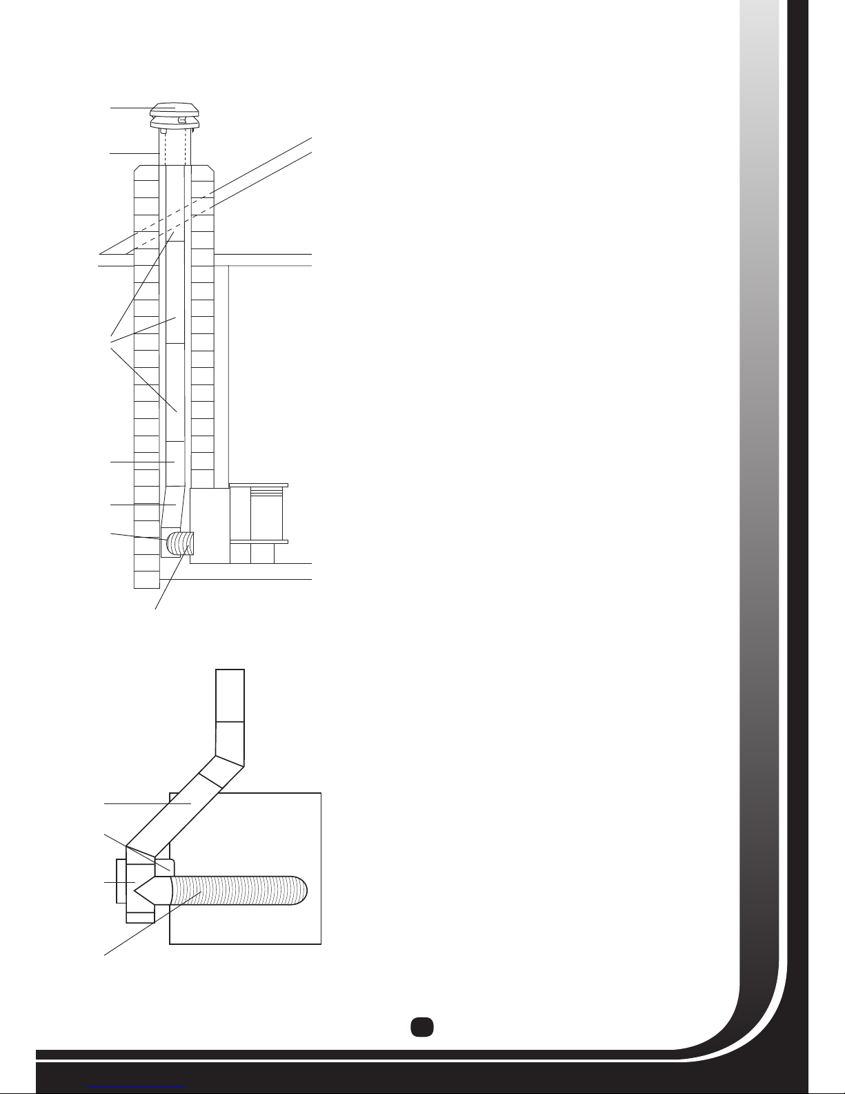
PELLET FIRE FREESTANDING VENT SYSTEM INSTALLATION
IMPORTANT NOTE TO THE INSTALLER – Pellet fire “vent systems” are pressurised at all times during
the operation of the appliance, and it is crucial that every joint in the vent system is fully sealed using
suitably rated “high temperature silicone” [Pioneer supply industrial grade RTV silicone suitable for this
purpose] NOTE;
•Ifjointsarenotfullysealedashwillblowintotheroom.
•Priortocommencinginstallationensurethat;
- Abuildingconsenthasbeenissuedfortheinstallation.
- Youarecompetentandcapabletocarryoutthisinstallation.
- Youhavereadandfullyunderstandtheseinstructions.
- Youhaveasuitableashingavailablewhichisappropriatefromtheroofmaterialyouare
penetrating.Youalsohaveasuitablesiliconforboththeashingandtosealallthejointsof
theventsystem.
- Youhavecheckedtoensureallthecomponentsoftheventsystemaslistedbeloware
includedwiththekit;
A - 2 x Black Painted 100mm diameter S/S vent pipes
B - 1 x 100mm diameter S/S vent pipe
C-1x“T”piecewithcaptted[capisremovablewithgasketseal]
D - 1 x Plastic coated black ceiling plate
E -1xMountingplatewith200mmdiameterstublinerattached
F -1x150mmdiametergalvanisedcasingwith“slipliner”
G -1xCowlassembly
H - 1 x Centralising bend
I -1xBagofbolts/screws
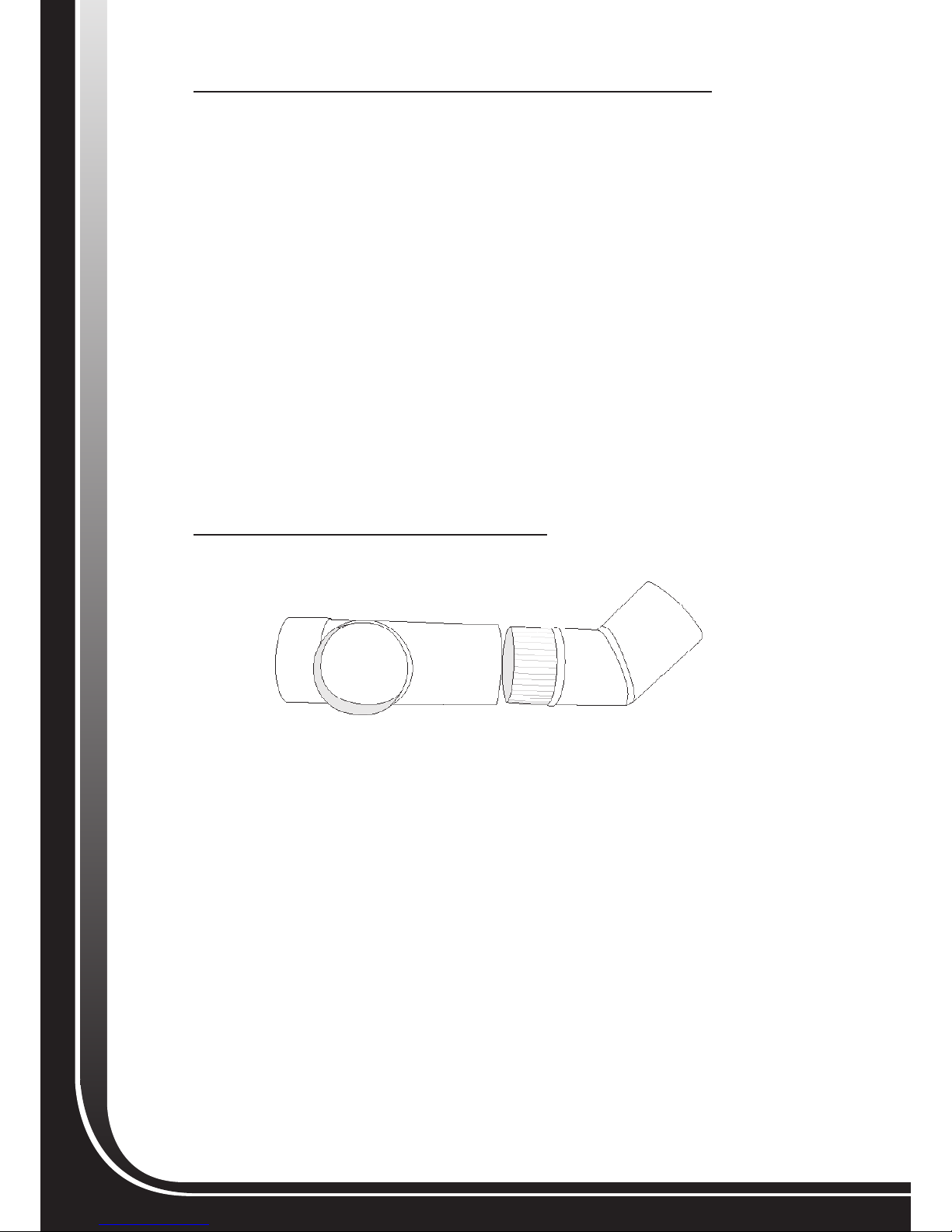
VENT KIT INSTALLATION INSTRUCTIONS
1. Place the capped “T” on a at surface, then align the centralizing bend so it is pointing up on a 45
degree angle as illustrated below, smear the inside with silicone then push in the crimped end of the
bend and secure with 3 x s/s rivets.
2. Attach the assembled “T” piece and centralizing bend to the vent outlet of the pellet re and position
it so the top of the centralizing bend is in the centre of the pellet re and pointing vertically up
towards the ceiling. (Refer to illustration on page 2) Secure in place using 4 x self tapping screws and
silicone sealant.
3. Position the pellet re in the desired location, check that the pellet re and oor protector have
adequate clearances/projections and that the vent system will be clear of ceiling joists, trusses, etc.
(refer to the pellet re installation manual) Once you have positioned the pellet re, secure it to the
oor using suitable anchors. Drill through the oor protector and into the oor using the two 8mm
holes provided at the rear of the pellet re base.
4. At a point directly above the pellet re vent centre, cut a 200mm square hole through the ceiling and
a 150mm hole through the outer roof lining. Trim out the top face of the ceiling, using timber nogs
creating a square aperture measuring 200mm internally.
5. Fit the mount plate into the ceiling by sliding the 200mm diameter stub casing attached to the
mounting plate up into the ceiling until the two upturned edges of the mount plate rest against the
underside of the ceiling. Square the mount plate to the wall and secure into location with the
4 x screws supplied into the nogs just tted.
6. Moving onto the roof with the 150mm diameter galvanised casing, lower the slotted end of the casing
into the roof cavity until it locates inside the brackets on the top face of the mounting plate. Return
back into the room and using the two x 6mm bolts and washers supplied. Securely bolt the base of
the 150mm diameter casing to the rivet nuts pre-tted into the mount plate brackets.
7. Return back onto the roof and using a suitable ashing, weather proof the joint where the 150mm
diameter casing penetrates the roof. (By tting brackets securing the casing to the roof material will
further improve the rigidity of the installation.)
9
8. Moving back into the home, remove the plastic lm from
the ceiling plate and place it black side down onto the
top of the pellet re.
9a. Unwrap the two painted vent pipes taking care not to
mark the painted surface and proceed to assemble the 3
x 100mm diameter vent pipes as described below.
9b. Smear an adequate amount of silicone sealant inside
the top/un-crimped ends of the 2 painted vent pipes
only.
9c. Taking the unpainted vent pipe insert its top/un-crimped
end up through the mounting plate until its bottom
crimped end is about 1250mm above the top of the
pellet re
9d. Taking one of the two painted vent pipes, t its lower
crimped end into the top of the centralizing bend
previously tted to the rear of the pellet re in item 2.
Lower the unpainted vent pipe which is protruding
down from the mounting plate so that it fully connects
into the lower painted vent pipe. Ensure these two vent
pipe sections are rmly connected and aligned, then
secure using three stainless steel rivets spaced equally
around the joint.
9e. Lift the two assembled vent pipe sections so the
bottom of the lower section is 1250mm above the top
of the pellet re and repeat the above procedure to t
the remaining painted vent pipe. Wipe off any excess
silicone from joints.
9f. With all three vent pipe sections securely joined, lift the
bottom section of the vent pipe out of the centralizing
bend then move it slightly off centre and allow it to rest
on the centralizing bend. Smear an adequate amount of
silicone sealant inside the top of the centralizing bend
(move the vent pipe assembly as required to ensure the
entire surface is coated with silicone sealant) Place the
ceiling plate over the centralizing bend so the centre
hole is directly above the centralizing bend tted to
the pellet re, then lower the vent pipe into the top of
the centralizing bend, with the vertical vent pipe seam
facing the rear.
9g. Carefully move the ceiling plate up the vent pipe
ensuring not to mark the painted surface and clip the
ceiling plate onto the mounting plate.
9h. Secure the lower vent pipe attached to the centralizing
bend using three stainless steel rivets spaced equally
around the joint.
9i. Making your way back onto the roof, slide the slip
section of the outer casing up until the top of the slip
section is level with the top of the vent pipe (+ or –
10mm) then secure this slip section to the outer
casing using rivets.
9j. Fit the stainless steel cowl into the vent pipe ensuring
the three brackets xed to the cowl t outside the
casing slip section. Drill through the pre punched holes
in all 3 brackets into the casing slip and secure with
self tapping screws to allow for future easy removal
during cleaning.
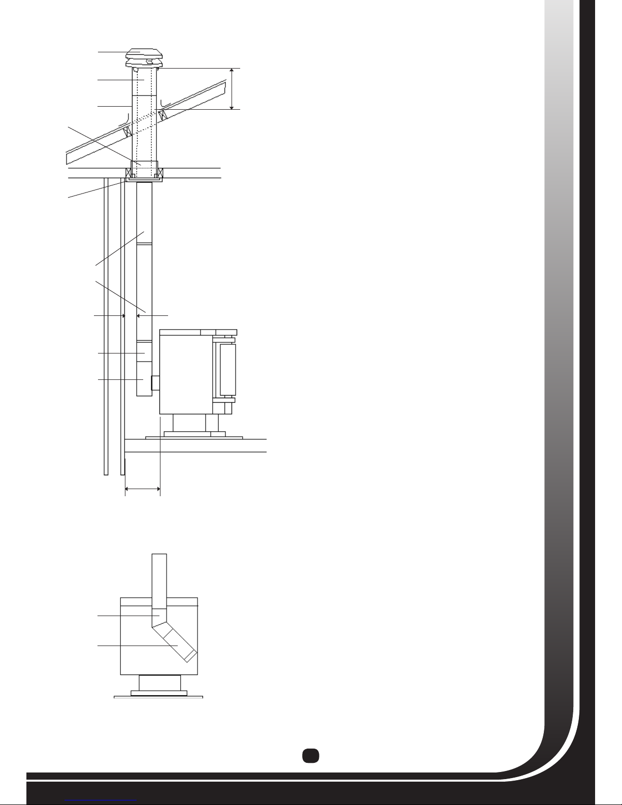
SIDE VIEW
REAR VIEW
A
D
E
F
B
G
C
H
C
H
600mm
minimum
250mm
100mm
minimum

10
PELLET FIRE INSERT VENT SYSTEM INSTALLATION
IMPORTANT NOTE TO THE INSTALLER – Pellet fire “vent systems” are pressurised at all times during the
operation of the appliance, and it is crucial that every joint in the vent system is fully sealed using suitably rated
“high temperature silicone” [Pioneer supply industrial grade RTV silicone suitable for this purpose] NOTE;
•Ifjointsarenotfullysealedashmayblowintotheroom.
•Priortocommencinginstallationensurethat;
- Abuildingconsenthasbeenissuedfortheinstallation.
- Youarecompetentandcapabletocarryoutthisinstallation.
-Somestainlesssteelcomponentsofthisventsystemhavesharpedges,beaware!
- Youhavereadandfullyunderstandtheseinstructions.
- Youhaveasuitableashingavailablewhichisappropriateforthechimney.
- Youalsohaveasuitablesiliconeforboththeashingandtosealallthejointsoftheventsystem.
- Youhavecheckedtoensureallthecomponentsoftheventsystemaslistedbeloware
includedwiththekit;
A - 3 x 1200mm lengths of 100mm diameter S/S vent pipe
B - 1 x 600mm length of 100mm diameter S/S vent pipe
C - 1 x 100mm S/S telescopic offset (2 piece)
D - 1 x 600mm length of 100mm S/S flexi flue bent 90 degrees one end
E -1x“T”piecewithcaptted[capisremovablewithgasketseal]
F - 1 x 150mm diameter galvanised casing
G - 1 x Galvanised angle bracket
H-1xCowlassembly
PRE INSTALLATION
All Metro Pellet Fires are tested using all applicable procedures and equipment under AS/NZS 2918:2001 when
installed in accordance with the installation and operation manual supplied with every Metro pellet re. Prior to
installing your Metro pellet re insert into a masonry chimney, it is important that certain clearances and other
requirements are complied with as detailed below
Chimney cavity – The chimney should be swept, rebricks removed if necessary, and the hearth of the replace
checked to ensure it is level.
Floor Protector – A oor protector must extend 531mm forward of the front of the replace cavity opening.
Electrical Requirements - Ensure a 3 pin electrical outlet is installed in the chimney cavity with a suitable isolation
switch adjacent to the appliance outside the cavity in accordance with New Zealand electrical regulations; if none exists
get a qualied electrician to install one.
Important – It is critical that the components of this Insert Pellet Fire Vent system are installed as detailed within these
instructions. This is necessary for the appliance to be moved from the chimney cavity for annual cleaning and servicing,
then reinserted without having to disconnect or alter the vent system.
INSTALLATION
1. The galvanized angle bracket supplied must be attached to the “T” Piece as a means of securing the “T” inside the
chimney cavity. This bracket has 4 sets of holes pre-punched enabling it to suit varying width chimneys. NOTE –
Most chimneys are approx 800mm wide and these instructions are based on this measurement [move the bracket
location on the “T” accordingly if the internal chimney width of your installation is more or less than 800mm]
- Place a liberal amount of silicon inside the “STRAIGHT END” of the S/S exi ue, and t this over the side entry of
the “T” piece. Place these two components on a at surface and ensure the 90 degree bend “IS AT THE LEFT END
POINTING UP” and the capped end of the “T” is “FACING YOU” [as illustrated in Figure 1]. Secure the exi ue to
the “T” using four stainless steel rivets at 90 degree spacings around the circumference of the joint.
- Now position the galvanised angle bracket in place with the 50mm fold “TO THE RIGHT FACING UP” and hanging
over the “T” by 15mm (as illustrated in gure 1).
Note – This bracket must be positioned “parallel” with the exi ue and “JUST TOUCHING” the removable cap of the “T” piece.
Firmly secure the bracket in position with a minimum of 4 stainless rivets drilling through the appropriate pre-punched holes and/
or drill others as required.
15mm
Figure 1
11
- With the “T piece, exi ue and bracket” now assembled, position
this pre-assembly into the “RIGHT HAND SIDE” of the chimney
cavity with the centre height of the “BRACKET” 300mm above the
base of the chimney cavity, and the two holes to be drilled into
the masonry through the brackets return fold 270mm back from
the chimney cavity entrance. Secure using two 6mm dynabolts or
equivalent masonry anchors.
2. Smear an adequate amount of silicone sealant inside the top/
un-crimped ends of the vent pipes. Secure the vent pipes together
ensuring the vent seams are in line. Vent pipe joints must be fully
compressed to ensure a good seal, and then riveted together at
3 even points around the vent join. For installations where extra
lengths of vent pipe are required, or when the weather is poor, it
will be easier to assemble the vent pipe lengths as they are lowered
into the masonry chimney. Prior to installing the assembled vent
pipe into the masonry chimney cavity, take careful note to ensure
there are no overhead power lines in close proximity. Lower the
vent pipe into the masonry chimney, with the crimped end entering
the top of the chimney cavity rst.
3. From inside the cavity hold the lower section of the vent pipe in its
approximate position and measure from the centre of the vent pipe
to the centre of the top outlet of the “T” piece. Smear an adequate
amount of silicone onto the slip section of the offset to ensure a
good seal and then adjust the telescopic offset to the centre to
centre measurement from the “T” piece to the vent pipe. Rivet the
offset in three locations around its circumference. (If the offset is
used in its fully compressed form, it will be necessary to modify the
end of the male slip section otherwise it will restrict the internal
diameter) Apply a liberal amount of silicone around the crimped
end of the lower vent pipe, lift the assembled vent pipes up high
enough to allow it to be inserted into the un-crimped end of the
offset, rivet together at 3 even points around the join, then t the
lower crimped end of the offset into the “T” outlet, silicone and rivet
into position.
4. Making your way back onto the roof secure the outer casing with
suitable fasteners and weatherproof seal to the masonry chimney
top with mortar or silicone. A masonry chimney ashing plate is
recommended and will need to be fabricated with an upturn to
secure the 150mm outer casing. Note: The top of the outer casing
must be “level” ( + or - 10mm) with the top of the 100mm stainless
steel vent pipe. Place the 100mm cowl over the vent and screw to
the 150mm casing and secure with S/S screws.
5. Moving back into the home, mark a line 320mm from the front
wall of the re place cavity opening out into the room, this will
give a 28mm gap for the facia to slide into once the pellet re is in
position.
6. Position the rear of the pellet re just out of and to one side of the
opening to allow maximum access, pull the exi pipe out to the re,
smear a liberal amount of silicone inside the pre-bent end of the
exi ue and push over the pellet re outlet then screw in place.
7. Fit the fascia and MX3 controller as per the instructions supplied
with the fascia.
8. Slide the unit back into the cavity until the mark lines up with front
of the base, TAKE CARE NOT TO DAMAGE THE EXHAUST FAN
WHICH PROTRUDES OUT TO THE LEFT.
9. Open the pellet re door drill and t 2 suitable fasteners to x
the unit to the oor, if using masonry fasteners use a rawl bolt or
similar so that the re can slide out over them when the bolts are
removed.
SIDE VIEW
REAR VIEW
A
B
C
E
D
F
H
C
G
D
E
12
Figure 4: Metro Pellet Fire
Insert Surround
USE NUTS
AND BOLTS TO
SECURE HERE
INSERT MX
CONTROL
PANEL HERE
(SECURE WITH
BLACK RIVETS
PROVIDED)
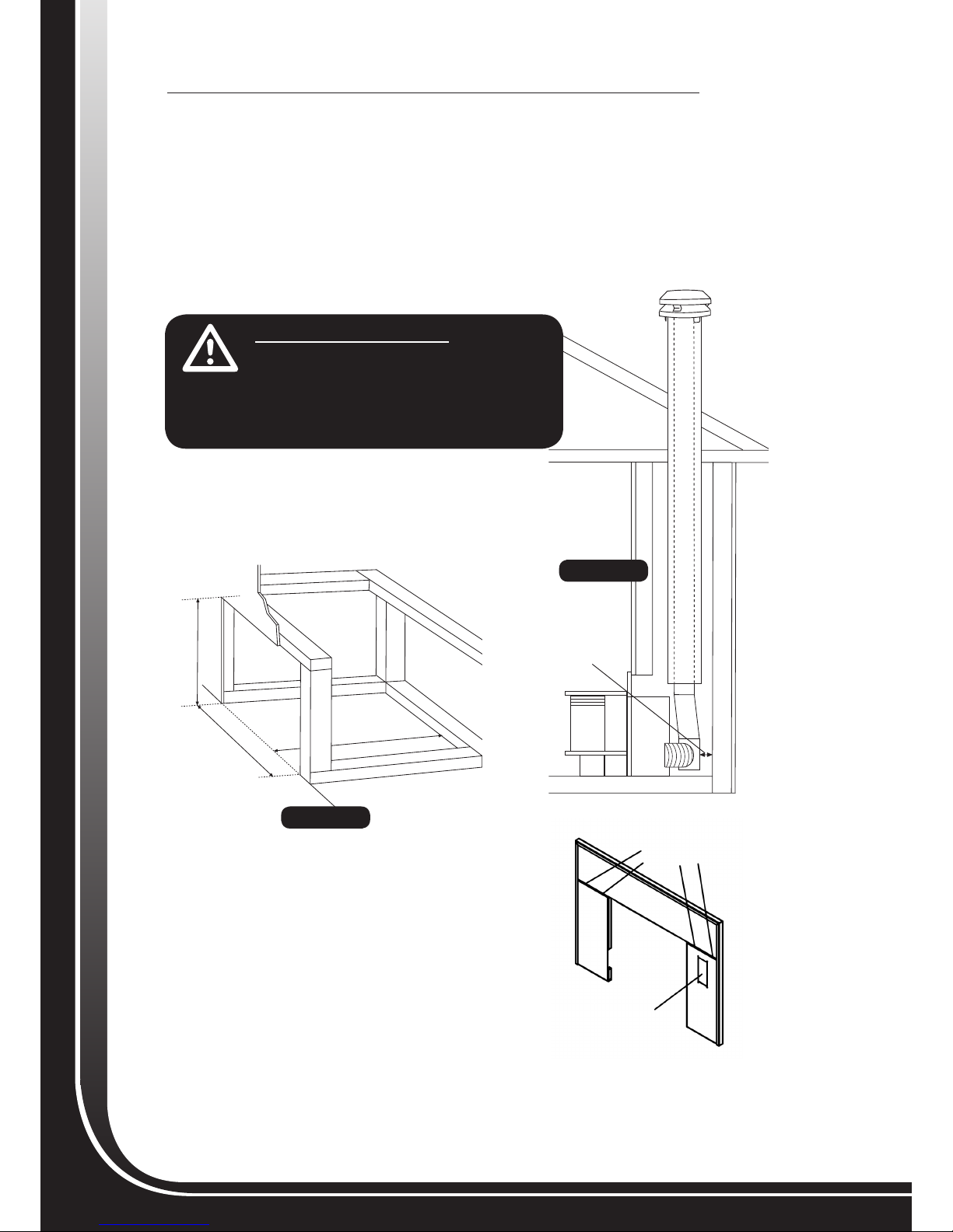
INSTALLING THE METRO PELLET FIRE INTO A TIMBER CAVITY
If the pellet re is being installed into a timber cavity installation,
1. Prepare the cavity opening to the minimum dimensions shown in gure 2 and line with non-combustible
material such as villa board.
2. The 100mm vent pipe must be fully cased with 150mm galvanised casings from the top of the
telescopic offset to the top of the vent pipe exiting the roof. (as shown in gure 3)
• These casings must be supported in position, either attached to the vent pipe, or to the inside of the cavity.
• This installation into a timber framed cavity will require a “Metro Pellet re Insert vent system”,
plus additional lengths of 150mm diameter galvanised casings with centralising brackets.
3. If heat sensitive material (i.e wooden oor)is located below the pellet re an insulated oor protector must
be installed. This oor protector must extend 150mm forward of the ashlip.
Figure 3
Figure 2
575MM
850MM
720MM
130MM MINIMUM
IMPORTANT MESSAGE
• ALL EXPOSED 100MM VENT PIPE INSIDE THE
CAVITY MUST BE A MINIMUM OF 130MM FROM ANY
COMBUSTIBLE MATERIAL.
• THE INSTALLATION OF THIS VENT SYSTEM AND
APPLIANCE IS TESTED AND APPROVED FOR THE
METRO BAY INSERT PELLET FIRE ONLY.
WARNING
WARNING
Fascia Surround
The METRO pellet insert surround can be seen in Figure 4.
The surround comes in 3 separate pieces and needs to be
assembled before being attached to the pellet re. Layout the
top and sides of the surround on the oor as shown in Figure
4. Verify that each side piece mounting holes are aligned
with the top piece mounting holes. Using the supplied nuts
& bolts, secure the side pieces to the top. Mount the MX3™
Control board as shown. Your surround is now ready to
mount to the insert.
13
Metro Pellet Fire Insert Removal
There may be some situations where the METRO pellet insert needs to be removed from the replace; venting
may need to be resealed, regular maintenance performed, etc....
Removal of the METRO pellet re insert from a replace is the reverse of installation with the following
exceptions: make sure the insert is not operating, has had sufcient time to cool down and that power to the
insert has been removed.
Operation and Maintenance
Please refer to the “Pellet Fire Operation” section of this manual for complete instructions on how to operate
your METRO pellet insert. The maintenance of the METRO pellet re insert is the same as the maintenance of a
free standing pellet re. Please read the “Maintenance” section for instructions on cleaning your insert, venting
and other maintenance precautions.
OPERATION – GENERAL OVERVIEW
The rst step in understanding your new METRO pellet re is to familiarize
yourself with its operation. Your pellet re has 3 main systems: Feed,
Combustion and Circulation.
These 3 systems work together to produce enough heat for your room. The
feed system uses an auger to “feed” the pellet fuel into the burn pot. The
combustion system provides the air for the fuel to burn and pushes the
smoke outside through the vent pipes.
The circulation system takes cold air from the room and pushes it through
the heat exchanger where it will warm up and ow back into the room as hot
air. These 3 main systems are all control by the MX3™ control system (see
Figure 5).
Safety features
1. Pressure Switch: This safety device is used to turn the feed off if pressure
is lost in the pellet re.
2. Circulation Fan Override: If your pellet re begins to overheat, this safety
device switches the circulation fan to the highest possible setting to try to
cool your pellet re down to a safe temperature.
3. High Limit/Manual Reset Thermal Disk: If the circulation fan fails to cool
the pellet re down fast enough, this thermal disk will turn the feed off .
This nal safety device guards against your pellet re from overheating. If
this thermal disk trips, the right side panel will need to be opened and the
thermal disk reset. See “Maintenance” and “Troubleshooting” sections for
more information.
Electric Igniter
Your METRO pellet re is equipped with an electric igniter. The electric igniter
is a convenient way of lighting a re in your pellet re without the use of lighter
gels or starter fuels.
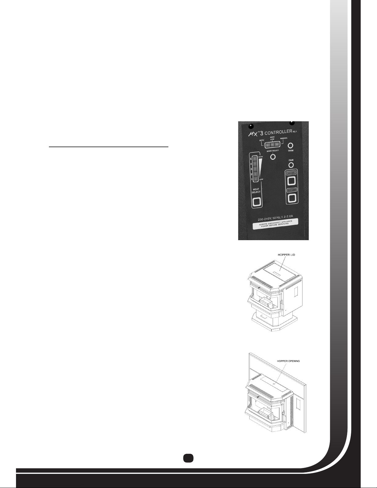
Fueling the Hopper
On the free standing pellet re model there is a lid covering the hopper. Pull
up on the handle, as shown in Figure 6 to load the hopper with fuel (the free
standing pellet re can hold up to 20 kgs of fuel). For the insert pellet re
models, remove the cover plate as shown in Figure 7. Load the fuel into the
opening to ll the hopper. The insert pellet re model can hold up to 18 kgs
of fuel.
Figure 6: Free standing
Pellet Fire Hopper Lid
Figure 7: Insert Pellet
Fire Hopper Opening
Figure 5: MX3™ Controller

14
OPERATION – MX3™ CONTROLLER
Basic Description
The MX3™ control is a digital control that uses a computer to control the operation of your pellet re. You should
be familiar with all of the buttons on this control before using your pellet re. Each button and their function are
described here.
“AUTO,HIGH/LOW,MANUAL” Switch
Your pellet re is capable of operating in 3 different modes; “AUTO”, “HIGH/LOW” and “MANUAL”.
Mode Selection Guide
Switch Position Thermostat/Timer
Required Description
MANUAL NO
Relies on a person to press the ON/OFF button located on the control
panel. The pellet re will automatically light.
HIGH/LOW YES
Switches heater from user setting to factory LOW setting based on
wall thermostat, remote control, wall switch or other switching device.
AUTO* YES
Turns Heater ON and OFF based on wall thermostat, remote control,
wall switch or other switching device. Turns Heater ON and OFF based
on wall thermostat, remote
1. “MANUAL” Mode: When used in this mode, your pellet re is controlled from the control panel only. When the
pellet re is in the “MANUAL” mode, the pellet re will not respond to any external switch (i.e. thermostat).
The pellet re will automatically light itself when it is rst turned on. When the “HEAT SELECT” light comes
on, choose the heat setting you want to operate the pellet re at. The pellet re will continue to operate at this
heat setting until you decide to change it or want to turn the pellet re off (by pressing the ON/OFF button).
2. “HIGH/LOW” Mode: With the switch in this position, your pellet re will alternate from a factory preset low
level to the setting you have chosen with the “HEAT SELECT” button (see “HEAT SELECT: Button” section
for more information). This mode is almost exclusively used with an externally wired switch and is highly
recommended since it can create substantial fuel savings. The pellet re will automatically light itself when it
is rst turned on. When the thermostat senses that heat is required, the pellet re will operate at the setting
you have chosen with the “HEAT SELECT” button. When the thermostat is satised, the pellet re goes down
to the factory preset low level.
3. “AUTO” Mode: With the switch in this position, your pellet re will turn itself on and off based on an externally
wired switch. The most common use of this mode is a programmable or non-programmable wall thermostat.
When wired to a thermostat, the pellet re will automatically light itself when the thermostat senses that heat
is required and will automatically turn itself off when the thermostat is satised. This mode can also be used
with a wall switch or remote controls. Consult your local dealer or visit WWW.METROFIRES.CO.NZ for more
information on available options.
“ON/OFF” Button
This button allows you to turn the pellet re on and off. Once pressed, the pellet re will go through a start-up
sequence and the ON/OFF light will blink. During this time, the feed rate is preset and the “HEAT SELECT” button
is disabled. Once the pellet re is warm enough, the “ON/OFF” light will stop blinking and you will be able to
change the heat setting with the “HEAT SELECT” button.
“HEAT SELECT” Button & Bar Graph
There are 5 possible heat settings for your
pellet re. Each setting is indicated in the
bar graph; 1 being the lowest, 5 being the
highest. Pressing the “HEAT SELECT” button
will change the heat setting as indicated
in the bar graph. Each time the button is
pressed, your pellet re will go to the next higher heat level (from 1 to 2, 2 to 3 etc...). Once the heat level reaches
the highest setting (5) and the “HEAT SELECT” button is pressed again, the heat level will return to the low setting
(1). Please note that during the start-up period, the “HEAT SELECT” button is disabled. At some point during the
start-up period, you will be able to set the heat level but the pellet re will not operate at the desired setting until it
IMPORTANT MESSAGE
• DAMPER CONTROL – PLEASE ENSURE
DAMPER IS FULLY OUT FOR SETTINGS 3,4 &
5 AND FULLY IN FOR SETTINGS 1 & 2.
WARNING
15
has warmed up properly. Also, your pellet re will always remember which heat setting was used last and return to
that setting next time the pellet re is turned on (Power failures will result in this setting being lost). Depending on
conditions you may need to adjust the side damper, generally IN for setting 1 and 2, fully OUT for settings 3, 4 and 5.
“AUGER” Button
Your pellet re uses an auger system to feed fuel into the burn pot. When the auger system is working, the
“AUGER” light will be on. During normal operation, this light should blink periodically. Holding the “AUGER”
button will run the auger system continuously. This button should only be used to ll the auger with fuel. Using
this button during normal operation will cause too much fuel to fall into the burn pot and may result in damage to
the pellet re or an unsafe situation.
“FAN” Button
During normal operation of your pellet re, the circulation fan (blows air into the room) speed can only be changed
by changing the heat setting (see “HEAT SELECT” button) The “FAN” button is used to override the factory fan
setting and run the circulation fan on the highest setting. Pressing the “FAN” button again will return the fan to its
original setting.
“TRIM” Button
Not set for use with the Metro Pellet Fires.
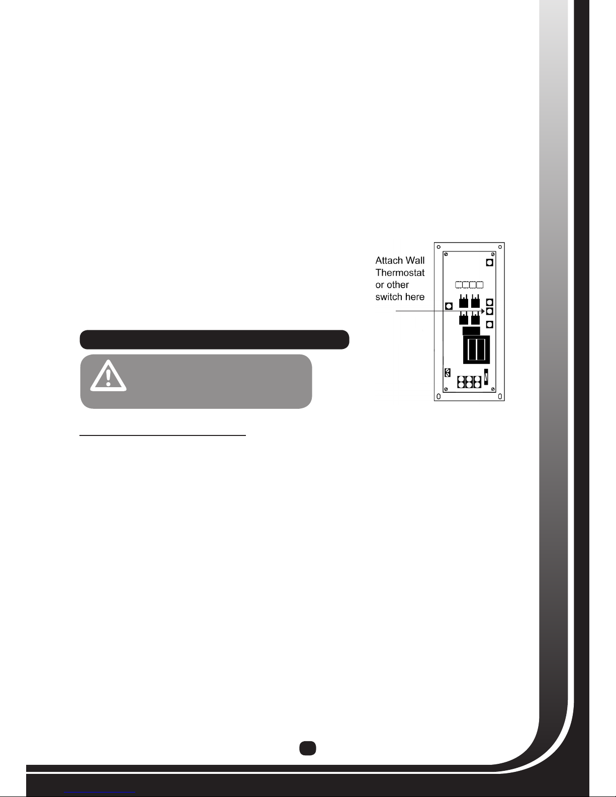
Wall thermostat, wall switch or other switching device.
The MX3™ control is capable of using an external switch (such as a
millivolt programmable or non-programmable wall thermostat) to turn
the pellet re on and off. The switch/thermostat must be wired to the
blue terminal block as shown in Figure 8.
Please Note: Thermostat option not available in Canterbury
STARTING YOUR PELLET FIRE
This method applies to all modes of operation (“AUTO, HIGH/LOW, “MANUAL”). For “AUTO” mode, use thermostat
or other switching device in lieu of “ON/OFF” button. Once your pellet re is properly installed, complete the
following steps to start your pellet re:
1. Ensure that there is adequate fuel in the hopper and that all ash gates and doors are closed.
2. Make sure side damper is fully out
3. Press the “ON/OFF” button. The following should happen
a. The “AUGER” and “ON/OFF” light will blink.
b. The exhaust fan will start.
c. The circulation fan will remain off (will come on after the start up cycle when the pellet re reaches
operation temperature.
d. Igniter will come on.
4.
If the auger tube is full with wood pellets, proceed to step 4. If the auger tube is empty, (i.e if this is the rst time
you are starting the pellet re or it has been run out of wood pellets) proceed with the following instructions:
a. Press and hold the “AUGER” button; the “AUGER” light should stay lit until the button is released.
b. Continue to hold the “AUGER” button until fuel begins to drop into the burn pot. This may take several
minutes.
c. Once the fuel begins to drop into the burn pot, this means that the auger tube is full with wood pellets.
Release the “AUGER” button.
d. If the pellet re turns off before the fuel begins to drop into the burn pot, press the “ON/OFF” button to
restart the pellet re. Repeat steps a-c.
5. After the fuel begins to drop into the burn pot it takes about 5-8 minutes for a ame to appear. Allow the
ame to stabalize for 15 minutes
6. Adjust the heat setting as desired (see “MX3™ Control” section).
7. If the pellet re shuts OFF during the start up cycle and there is still a ame, press the “ON/OFF” button again.
• TO PREVENT INJURY OR DAMAGE TO
THE PELLET FIRE, ALWAYS UNPLUG
THE PELLET FIRE FROM THE POWER
OUTLET BEFORE SERVICING.
CAUTION
Figure 8: Wall thermostat terminals
16
Stopping your Pellet Fire
To stop your pellet re, simply press the “ON/OFF” button (for “AUTO” mode, switch the thermostat or other
switching device to “OFF”). This will cause the feed system to stop (the “AUGER” light will stop blinking) and the
ame should die out within 5 minutes. The exhaust fan and circulation fan will continue to run until you pellet re
is cold (approximately 30 minutes). DO NOT turn OFF electrical power to stop the pellet re, as this may result in
your pellet re overheating.
IMPORTANT MESSAGE
• DO NOT USE FLAMMABLE LIQUIDS OR AEROSOLS TO START OR REKINDLE THE FIRE.
• DO NOT USE FLAMMABLE LIQUIDS OR AEROSOLS IN THE VICINITY OF THIS
APPLIANCE WHEN IT IS OPERATING.
• MAKE SURE THE AMOUNT OF FUEL IN THE BURN POT DOES NOT EXCEED THE HEIGHT OF THE BURN
POT AT ANY POINT DURING OPERATION. THIS CAN CAUSE SEVERE DAMAGE TO YOUR PELLET FIRE.
• DO NOT BURN GARBAGE OR FLAMMABLE FLUIDS SUCH AS GASOLINE, NAPHTHA OR ENGINE OIL
• THE PELLET FIRE IS HOT WHILE IN OPERATION. KEEP CHILDREN, CLOTHING AND FURNITURE AWAY.
CONTACT MAY CAUSE SKIN BURNS.
WARNING
MAINTENANCE & CLEANING
During normal operation, your pellet re produces a lot of yash. This yash will collect in the vent pipes and
inside your pellet re and restricts the ow of the ue gases. Improper maintenance leads to poor performance,
component failure and can be dangerous. Please adhere to the following maintenance schedule :
Before each heating season:
1. Clean the venting system. If there is a signicant amount
of soot build up, it should be removed to prevent the risk
of a chimney re. By making sure the exhaust venting
system and the pellet re itself are being maintained
properly and are cleaned on a regular basis, you reduce
the likelihood of a chimney re occurring.
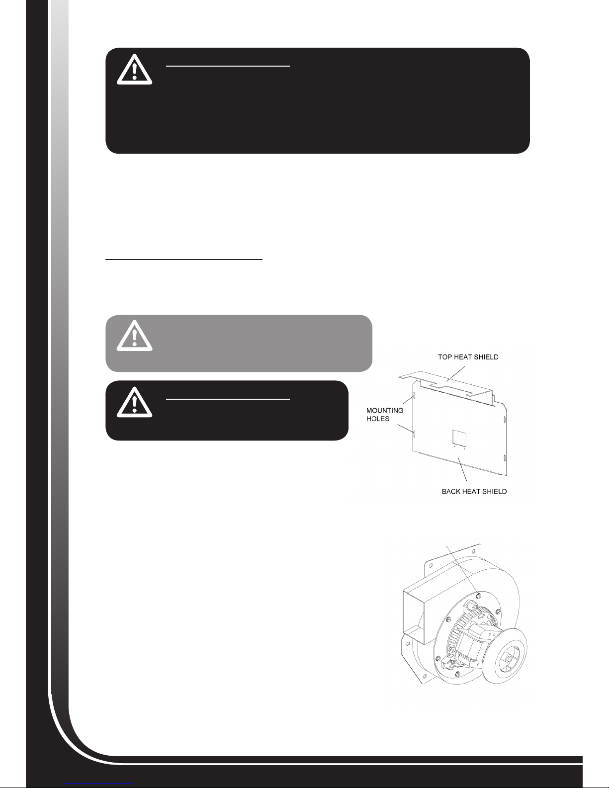
2. Clean behind the back heat shield as well as all exhaust
passages. Ashes can build up behind the back heat shield
and inside the exhaust passages.
To remove the back heat shield you must remove 4 bolts
located at each corner of the heat shield. On some models
the side heat shields must rst be removed by removing the 2
bolts holding them in place. Using a brush, remove all of the
ashes that have built up on the back wall of the combustion
chamber, on the inside of the heat shield as well as in the
exhaust passage. Inspect the auger chute gasket at this time.
Make sure the gasket is still in good condition and that it is in
the original position when the back heat shield is bolted back
into position. Make sure to clean behind the back heat shield
after every 3 tons of fuel burned.
Figure 10: Exhaust fan housing
Figure 9: Heat Shield
• DO NOT USE ABRASIVE CHEMICALS TO CLEAN THE
PELLET FIRE AND/OR LABELS PLACED ON THE
PELLET FIRE. THESE CHEMICALS CAN DAMAGE BOTH
THE PAINT AND LABELS ON THE PELLET FIRE.
CAUTION
IMPORTANT MESSAGE
• ALLOW THE PELLET FIRE TO COOL TO ROOM
TEMPERATURE AND UNPLUG THE PELLET FIRE
BEFORE PERFORMING ANY MAINTENANCE.
WARNING
REMOVE THESE
SCREWS
17
3. Clean the exhaust fan and housing. Ash accumulation on the fan blades will reduce the life of your exhaust
fan. Frequent cleaning will help extend the life of this component. Open the left side panel to access the
exhaust fan. Using a Common (at head) screw driver, remove the 6 sheet metal screws holding the fan motor
to the housing (See Figure 10). Using a brush, clean all ash from the exhaust fan blades and housing.
4. Inspect the condition of the door gasket periodically and replace it as necessary. It is important to make
sure the door gaskets are in good condition. Gaskets in poor condition will not allow the door to seal properly
and the pellet re will not function as efciently.
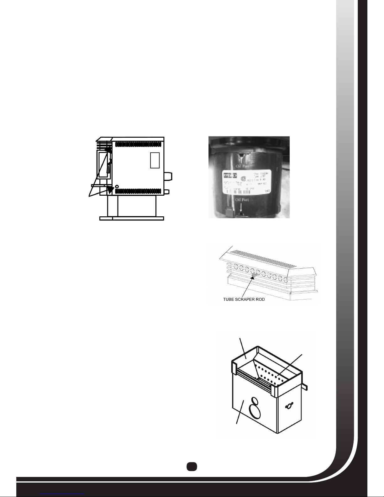
5. Oil the circulation fan motor. To oil the motor bearings, the right hand side panel must rst be opened. This
is done by removing the 2 screws near the front of the pellet re as shown in Figure 11. Use a square head
or Phillips screwdriver to remove the screws. You will now be able to swing the panel open and access the
circulation fan. There are 2 oil ports located on the top of the motor, one near the end and one near the fan
housing as shown in Figure 12. There may be rubber plugs in one or both of these oil ports. These plugs must
be removed prior to and replaced after oiling. Place a few drops of light oil, such as sewing machine oil, in
each port.
6. Perform weekly maintenance.
1. Pull and push the tube scraper rod located in the center,
above the door (See Figure 13). This will remove the ash
deposits on the heat exchanger tubes. The removed ash will
fall on the top heat shield, located in the burn chamber.
2. Lift the top heat shield and remove it carefully as there may
be a signicant amount of ash on it. Using a brush, clean the
top heat shield and dump the ashes into the burn chamber.
3. Clean the burn pot assembly (Figure 14) thoroughly. Lift the
splash guard up off of the burn pot assembly and remove.
Lift the burn pot out of the burn pot stand. Remove any
ashes that have built up inside of the burn pot and make
sure that all of the holes are clear of ashes and debris. Lift
up on the burn pot stand and pull towards you to remove.
Make sure there are no ashes remaining in the burn pot
stand. Failure to do so can be a re hazard. Place all ashes
into a metal container with a tight tting lid.
4. Using the brush, clean the walls and oor of the burn
chamber.
5. If your unit is equipped with the large ashtray, open the
ashtray slightly and pull on each ash gate (Figure 15) until
the ash falls from the burn chamber into the ashtray. Do
not pull the ash gates too far as they may fall out. Sweep
remaining ashes into the ashtray. For models with no
ashtray, scoop out the ashes into a metal container with a
tight tting lid.
Figure 11: Holes for screws on thr right side panel Figure 12: Oil ports on a circulation fan
REMOVE THESE SCREWS TO
OPEN THE SIDE PANEL
Figure 13: Tube scraper rod to clean the heat
exchanger pipes
Figure 14: Burn pot stand assembly
SPLASH GUARD
BURN POT
BURN POT STAND

18
6. Close the ash gates (if equipped) and remove the
ashtray. Dispose of the ashes in a safe manner.
If the ashes are stored in a container, make sure
the lid is secure. DO NOT place the container on
a combustible surface. Replacement of ashtray is
reverse of removal.
NOTE: Ashes should be placed in a metal container with a tight
tting lid. The closed container of ashes should be placed on
a noncombustible oor or on the ground, well away from all
combustible materials, pending nal disposal. If the ashes are
disposed of by burial in soil or otherwise locally dispersed,
they should be retained in the closed container until all
cinders have been thoroughly cooled. Do not place any other
waste materials in this container.
7. Empty out the hopper once every 2 weeks. Vacuum
all the sawdust build up in the hopper and auger
chute opening.
8. Reinstall all removed parts to their original positions.
9. Clean the glass with a mild glass cleaner when dirty. DO NOT clean the glass when the door is hot. This is
very important to see if the pellet re is burning properly or not. DO NOT hit the glass or slam the door shut.
This may cause the glass to crack or break. DO NOT operate the pellet re if the glass is cracked or broken.
DO NOT replace the glass with any type of glass other then an APR Industries Ltd. factory approved glass. If
the glass cracks or breaks, turn the pellet re OFF. DO NOT operate the pellet re until the glass has been
replaced.
NOTE: Depending on the type of fuel you use and the frequency that you use the pellet re, you may need to clean the pellet re
more frequently.
After each heating season:
1. Remove all the pellet fuel from the hopper. Run the pellet re to empty the auger tube. Vacuum the hopper
and auger tube. Clean the rest of the pellet re.
2. Open up both side panels and clean out any pellets, dust, ashes or debris that may have built up in the back of
the pellet re. Once at the back of the pellet re is cleaned, close both side panels.
Figure 15: Ash gates for a Metro pellet fire
ASH DOOR GATES
19
TROUBLESHOOTING GUIDE
Troubleshooting
Your METRO pellet re is equipped with a diagnostic light feature. When a problem occurs, the heat setting bar
graph will light up to indicate where the problem may be.
Each light has been numbered for easy identication. The chart below has been included to help you determine
which corrective action should be taken. A complete description of each corrective action is included in the
following pages of this manual. Some problems, such as ame problems, will not cause the diagnostic lights to
light up.
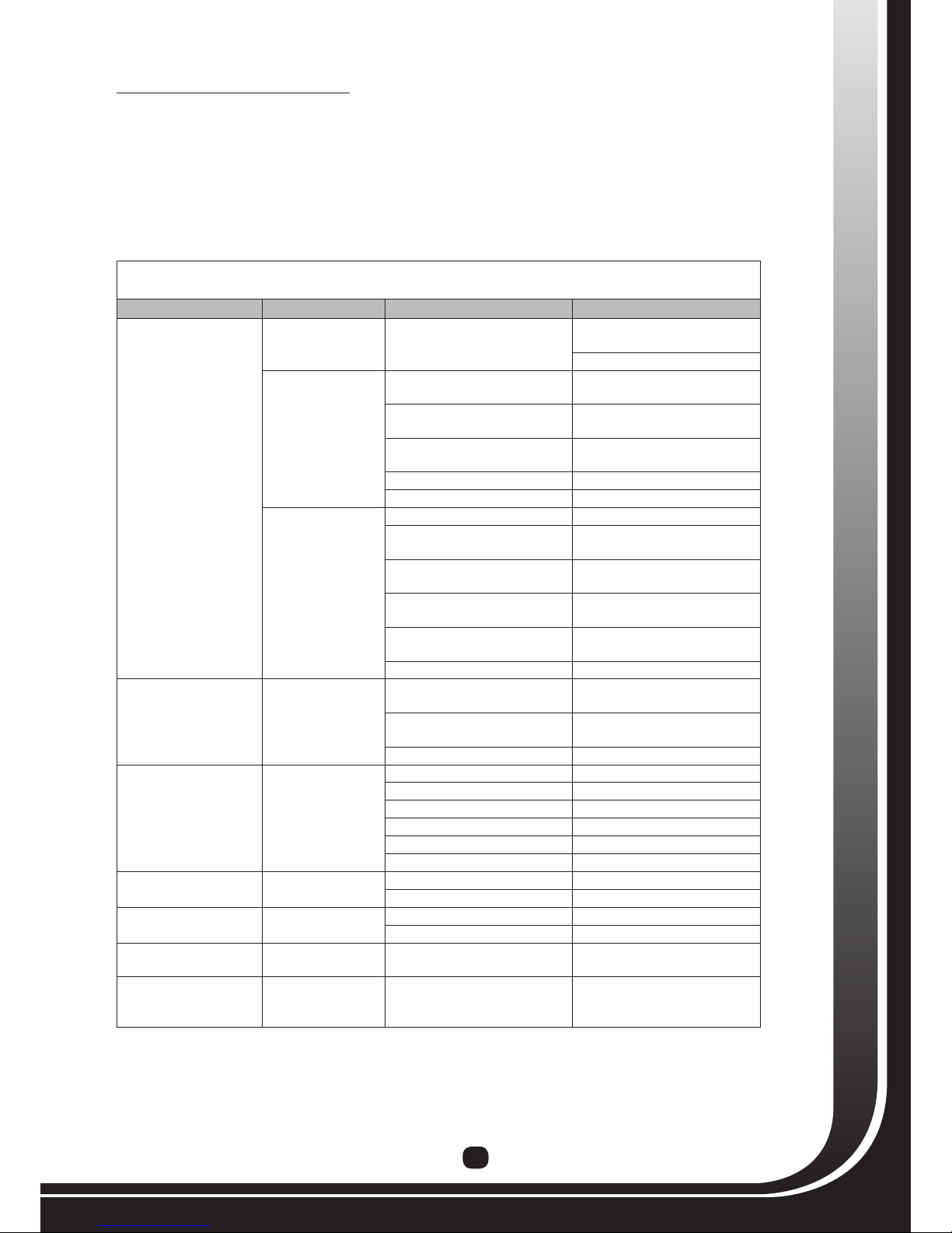
MX3™ Control Trouble Shooting Guide
Problem Light Status Possible Causes Remedy
Heaterwillnot
feed pellets
All lights off No power.
Check to see if heater is plugged
in.
Check electrical outlet for power.
#2 light blinks
(Pressure system
failure)
Exhaust vent and exhaust fan are
blocked
Clean exhaust venting and
exhaust fan.
Exhaust passage and exhaust box
pressure tap are blocked.
Clean exhaust passage and
pressure tap.
Pressure switch tube is cracked
or broken Replace pressure switch tube.
Pressure switch has failed. Replace pressure switch.
Exhaust fan has failed. Replace exhaust fan.
#3 light blinks
(Proof of ame
failure)
Hopper is empty. Fill hopper with fuel.
Manual reset thermal disk has
tripped.
Reset the manual reset thermal
disk.
Manual reset thermal disk has
failed.
Replace the manual reset
thermal disk.
Exhaust fan thermal disk has
failed. Replace exhaust fan thermal disk.
Auger jam. Empty hopper and clean out
auger
Auger motor has failed. Replace auger motor.
Stovewon’tturnoff. Normal
Exhaust fan thermal disk has
failed. Replace exhaust fan thermal disk
Stove in “Cool Down” mode. Allow sufcient time for the stove
to cool down.
MX Control board has failed. Replace MX Control Board
Stovewillnotlight Normal
No pellet fuel. Add fuel to hopper.
Burn pot dirty. Clean burn pot.
Fuse blown. Replace fuse
Igniter slipped out of igniter tube. Push igniter back into place.
Igniter has failed Replace igniter.
No power to igniter. Replace MX Control Board
Fuelpilesup. Normal Burn pot dirty. Clean burn pot.
Poor quality fuel. Change fuel supplier.
Short flame on high feed Poor quality fuel. Change fuel supplier.
Heat exchanger requires cleaning Clean heat exchanger.
Too large and dark
orange flame Poor quality fuel. Change fuel supplier.
Smell of smoke
in the room Normal The pellet venting joints not
sealed properly.
Seal all joints with high
temperature RTV siliconne
sealant.

20
Corrective Actions
Proof of Flame Failure
1. Verify that there is sufcient fuel in the hopper and that the pellet re has run for long enough to ll the auger
tube. (See “Starting (lighting) your Pellet Fire for the First Time” section)
2. Verify that the auger has not jammed. Occasionally, fuel can become lodged in the auger and prevent the
auger’s proper operation. Open one of the side panels and grasp the auger motor. Move the auger motor back
and forth. It may be difcult to move at rst but should move relatively freely. If it will not move, empty the
hopper and look for foreign objects in the auger.
3. Verify that the auger motor is working. Plug the pellet re in. Without lighting a re, start the pellet re. Verify
that the white plastic fan on the auger motor is turning. If it does not turn, check for power at the auger motor
and replace the auger motor as necessary. Remember to unplug the pellet re before attempting any service.
4. Verify that the auger is properly secured to the motor. Empty the hopper and locate the auger bolt
(approximately 1/4” square heat) on the auger. Remove the bolt and make sure the hole is aligned with the at
portion of the auger motor shaft. Reinstall the bolt and tighten.
5. Check the manual reset thermal disk. If the manual reset thermal disk has tripped, you will need to reset it.
6. If none of the above resolve your problem, contact your local METRO dealer.
Pressure Switch Failure
1. Verify that all doors, ashtrays and ashgates are properly closed and well sealed. If any leakage is present,
replace appropriate gaskets.
2. Verify that the pellet re is clean. Clean all venting and exhaust passages in the pellet re. Refer to
“Maintenance” section for more information on cleaning your pellet re.
3. Verify that the pressure switch tube is not cracked or loose. Replace as required. Also verify that the pressure
port on the pellet re is clean.
4. Verify that the exhaust fan is in good working condition. When you start your pellet re you should hear the
exhaust fan start instantaneously. If the exhaust fan is not working, check for power at the exhaust fan and
replace the exhaust fan as necessary. Remember to unplug the pellet re before attempting any service.
5. Verify that the pressure switch is working properly. Apply a slight vacuum to the pressure switch tube. The
pressure switch should “click” when a vacuum is applied. Replace as necessary. Note: Pressure Switches
rarely fail.
6. If none of the above resolve your problem, contact your local METRO dealer.
Manual Reset Thermal Disk Failure
The manual reset thermal disk is a safety device to prevent the pellet re from overheating. This thermal disk will
trip when the body of the pellet re reaches a certain temperature. This section will describe the possible reasons
for the pellet re to overheat.
1. The circulation fan may have failed. Verify that the circulation fan is in good working condition. Start your
pellet re by pressing the ON/OFF button. Allow the pellet re to go through it’s normal start up cycle. Once
the pellet re has nished it’s start up cycle, the circulation fan should come on. Cycle through each setting by
pressing the Heat Select button. The fan should operate faster at the higher Heat Select settings.
2. The circulation fan override thermal disk may have failed. Verify that the circulation fan override thermal disk
is working properly.
3. The manual reset thermal disk itself may have failed. Verify that the manual reset thermal disk is working
properly.
4. If your Manual Reset Thermal Disk is continuously tripping, contact your local METRO dealer.
IMPORTANT MESSAGE
• BEFORE PERFORMING ANY SERVICE, MAKE SURE THE PELLET FIRE IS COLD AND UNPLUGGED. DO
NOT UNPLUG THE PELLET FIRE WHILE THE PELLET FIRE IS OPERATING OF IF THERE IS A FLAME.
WE STRONGLY RECOMMEND USING QUALIFIED SERVICE PEOPLE.
WARNING
This manual suits for next models
1
Table of contents
Popular Pellet Stove manuals by other brands


Centrometal
Centrometal PelTec 12 Technical instructions

Extraflame
Extraflame VIVIANA EVO user manual

RIKA
RIKA Memo operating manual

Ariterm
Ariterm MYSINGE Installation and operating instructions

calimax
calimax Solida operating instructions

Stanley
Stanley FUSION PELLET STOVE Operating & installation manual

Sierra Products
Sierra Products EF-5001UB Installation & operating instructions

Harman
Harman PC45 Installation & operating manual

England's Stove Works
England's Stove Works 25-PI Installation & operation manual

Ariterm
Ariterm EKERUM Installation and operating instructions

Heatilator
Heatilator ECO CHOICE ECO-ADV-PS35 installation manual

IronStrike
IronStrike Cascade Installation and operation manual