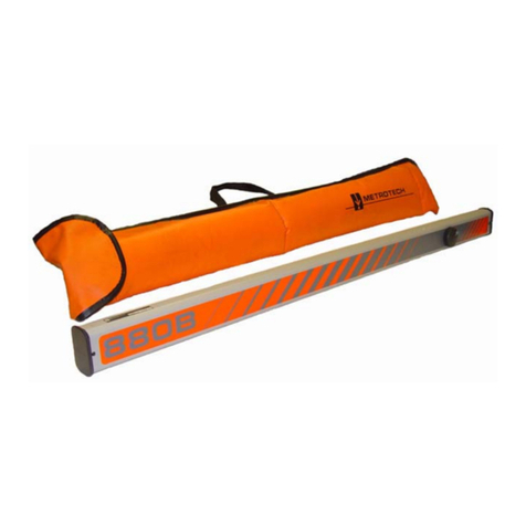
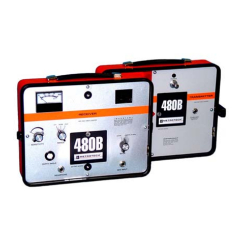
Metrotech 9800XT SFL2 Series User manual

9800XT™ SFL2
SERVICE CENTER, SALES AND TECHNICAL SUPPORT INFORMATION
Corporate Headquarters Metrotech Eastern U.S. Service Center Metrotech European Service Center
3251 Olcott Street 1824 Murfreesboro Road, Ste. 104 Seba KMT
Santa Clara, CA 95054 Nashville, TN 37217 Dr. Herbert Iann St. 6
800-446-3392 800-624-6210 96148 Baunach, Germany
408-734-1400 Direct 615-366-7323 Direct +49 9544 680
408-734-1415 Fax 615-360-9855 Fax +49 9544 2273 Fax
www.metrotech.com nashville@metrotech.com service@sebakmt.com
sales@metrotech.com
Warranty: One year. Specifications Subject to change without notice, ISO 9001:2000 Certified. Copyright 2008. All Rights Reserved. Rev 12/01/07
OPERATIONS MANUAL
Sheath Fault Locator

2
ISO 9001 CERTIFIED
Metrotech has received ISO 9001 Quality Management System Certification.
Metrotech adheres to the quality standard guidelines of ISO 9001 and ensures
quality in its design/development, production, installation, and servicing
disciplines.
© Metrotech Corporation 2005-2008
Metrotech Corporation
3251 Olcott Street
Santa Clara, CA 95054
USA
Tel: 1.800.446.3392; 1.408.734.1400
Fax: 1.408.734.1415
Internet: www.metrotech.com
Revision C: 12/1/07

TABLE OF CONTENTS
List of Illustrations ………………………………………………………. .1
1 Introduction…….……..………………………….…………………………. 2
2 Safety Precautions………………………………………………………… ..3
3 9800XT SFL-2 Quick Start Guide for the Experienced User………. .4
4 9800XT SFL-2 Equipment………………………………………..….….. .10
4.1 Standard Equipment……………………………………….. .. .….….10
4.2 Optional Accessories…………………………………….. .. .…. . ….12
4.3 Technical Specifications…………………………………….. … …...13
4.4 Transmitter Controls and Indicators…………………………….……16
4.5 Transmitter Features………………………………………………….18
4.6 A-Frame Receiver Controls and Indicators…………………………..20
4.7 Additional A-Frame Receiver Features………………………………21
5 Principles of Operation…………………………………………………….22
5.1 Functional Theory…………………………………………………...22
5.1.1 Earth Voltage Gradient…………………. …………………………24
5.1.2 Equipotentials……………..………………………………………..24
5.1.3 Multiple Fault Patterns………………………………………..……26
5.1.4 Distortion Due to Adjacent Conductors……………………………26
6 Checkout Procedure……..…….. . ………………………. … .. .…. … ... 27
7 Operation…….…..…………………………………………………….…....29
7.1 Check the Batteries Prior to Going into the Field…… . . . . . . . . . …29
7.2 Ensure all conductors are de-energized.…………… . . . . . . .. .……29
7.3 Lift the Grounds………………. . . . .……………………………. ..29
7.4 Attach the Transmitter to the Conductor-Check Fault Resistance . . 29
7.5 Synchronize the A-Frame Receiver…. .…………………………….30
7.6 Confirm that a Fault Exists…………. . . . . .………………………..32
7.7 Trace the Cable with the 9800 Receiver…. . . . . . . .………………..32
7.8 Pinpoint the Fault…………….. …………………………. .……….32
7.9 Verify the Fault……………. . . .……. .. ..……………………….…32

8 Advanced Techniques…...….………………………………….…...……..33
8.1 Faults Under Inaccessible Surfaces…. . . . .………………………...33
8.1.1 Perpendicular Method………………………………………..……..33
8.1.2 Triangulation Method………….. .………………………… ………34
8.2 Faults Under Pavement…. ...……………………………… ……..35
8.3 Long Distance Tracing……. . . . . . .………… .. …… ……………35
8.4 High and Low Impedance Faults…. . . . . . . . . . . . . . ……………..36
8.5 Multiple Faults……. . . . . . . . .…………………………………. . .36
9 Maintenance…………………………………………………………… … ...37
9.1 Receiver Battery Replacement……… .. . . . . . . . . . . . . .. . ………37
9.2 Service Center………………………………… . . . . . . . . . .. .. ….38
Appendix ………………………………………………………………….. . ....39
Copyright…………………………………………………………………… ....40
Warranty……………………………………………………………….. .. … ...41

1
LIST OF ILLUSTRATIONS
Figure 3-1: Fault Resistance Scale.. . . . . .. . . . . . . . . . . . . . . . . . . . . .. . . . . . ..4
Figure 3-2: Clamping Black Lead to Ground Rod…..…….. ………………...5
Figure 3-3: Clamping Red Lead to Targeted Cable.………………………. ...5
Figure 3-4: Locating the Targeted Cable…………..………………. .… …… 5
Figure 3-5: Positioning of A-Frame Receiver for Synchronization………….6
Figure 3-6: Locating the Cable Fault with A-Frame Receiver…….………. .7
Figure 4-1: Standard Equipment and Accessories. . …… . . . . . . . . . . . . . . .. 11
Figure 4-2: Transmitter Controls Panel….……..…………… ……………….16
Figure 4-3: A-Frame Controls and Indicators. . . . . . . . . . . . . . . . . . . . . . . . . 20
Figure 5-1: Typical SFL-2 Transmitter Connection………………………… 23
Figure 5-2: Signal Pattern Around Fault and Ground Point……………..… 24
Figure 5-3: Multiple Fault Signal Patterns………………………………….. 26
Figure 6-1: Checkout Test Set-Up…………………………………….……… 27
Figure 7-1: Synchronizing the A-frame……………………………………….30
Figure 7-2: Fault Confirmation………………………………………………. 31
Figure 8-1: Perpendicular Method…………………………………………… 33
Figure 8-2: Triangulation Method…………………………………………… 34
Figure 8-3: Locating an Equipotential Circle……………………………….. 34
Figure 8-4: Fault Location Using Extension Cable for
Increased Sensitivity…………………………………………….. 35
Figure 9-1: Receiver Battery Replacement………………………………….. 37

2
1INTRODUCTION
The Metrotech 9800SFL Sheath Fault Locator system is designed to detect and pinpoint
sheath and other conductor faults that are in direct contact with the earth.
The 9800SFL offers these unique features:
♦ Fault level measurement at the Transmitter
♦ Simultaneous fault finding and line tracing.
♦ Signal strength LCD on the A-Frame for judging proximity to
faults, comparing multiple faults, and detecting pinholes and
“trees” in power cable.
♦ Detection of low and high resistance faults.
♦ Automatic battery checking and low battery warning
♦ Non-polarized A-Frame.
♦ Single-handed operation. No need to carry locator receiver as well
as A-frame.
Operation of the unit is completely automatic; there are no operator adjustments required.
Both the Transmitter and Receiver are water resistant and built to withstand the rigors of
field use.

3
2 SAFETY PRECAUTIONS
1 Metrotech Utility Line and Sheath Fault Locators are intended for use by utility
and contractor professionals. Safety hazards for underground utility access
areas include electrical shock, explosive gases, and toxic fumes as well as
potential influence on communications and control systems such as traffic control
and railroad crossings.
2 Familiarize yourself with all required safety practices of the local utility company,
or other owner of the plant before entering an access area or connecting a
Metrotech transmitter.
3 Before connecting transmitter directly to any conductor, make sure that the
line is de-energized and out of service. Never make a direct connection to a
live power cable.
4 If you use the Metroclamp on energized electrical or control lines follow
appropriate safety procedures to avoid the risk of injury.
5 Pay special attention when using a locator in high traffic areas.

4
3 9800XT SFL-2 SHEATH FAULT LOCATOR QUICK START
FOR THE EXPERIENCED USER
1 Check Batteries Prior to Departing for the Field
Check the batteries in the Transmitter, Receiver, and A-Frame.
Replace/recharge if necessary. Turn the instruments off.
2 Ensure all conductors are de-energized
3 Lift Grounds
Lift Grounds (of all conductors in the circuit) at both ends of the faulted cable
section.
WARNING
When the Transmitter is set to “SFL”, the external OUTPUT JACKS produce
High Voltage. Do not touch these jacks, electrical shock will result!
4 Attach Transmitter to Conductor – Check Fault Resistance
1 Turn Transmitter “OFF.”
2 Plug Black and Red leads into the Transmitter.
3 Stretch Black-lead 180 degrees away from conductor.
4 Push grounding rod into earth and clamp black lead to grounding rod.
Establish the best ground possible. See figure 3-2
5 Clamp Red lead to target conductor sheath. See Figure 3-3
6 Turn Transmitter power knob to “SFL” position.
Check fault resistance scale: See Figure 3-1
0-100k ohms – Severe Fault
100k – 500k ohms – Medium Fault
1 Megohm and above – Light Faults
Note: Read the number below the oscillating
bar to check the quality of the targeted
cable. The fault resistance on
Figure 3-1 is 10K ohms (Severe Fault).
Figure 3-1: Fault Resistance Scale

5
Figure 3-2: Clamping Black Lead to Ground Rod
Figure 3-3: Clamping Red Lead to Conductor
5 Use the 9800XT Line Locator Receiver to Trace the Cable
Trace and mark the cable as you proceed towards the fault.
Figure 3-4: Locating the Targeted Cable

6
5 Synchronize the A-Frame Receiver and establish reference value of fault
(A-Frame receiver has a one-color band above each spike (Black or White)
1 Hold the A-Frame Receiver so the spike with the black band is about 2 steps
away from the ground rod and the spike with the white band is in-line with the
targeted cable. The A-frame receiver must be placed as shown in figure 3-5
for synchronization and for unit to operate correctly. Push the A-Frame spikes
into the ground. Switch the Receiver “ON” wait until arrow flashes.
Figure 3-5: Positioning of A-Frame Receiver for Synchronization
2 Monitor bar-graph LCD display for arrow direction. If the arrow points
away from the ground rod, there is a fault.
3 If the arrow points towards the ground rod, there is no fault, and
grounds and connections need to be rechecked
4 The number of bars on the LCD indicates the potential gradient
associated with the fault at the synchronization location.
5 The number of bars will decrease when you move away from the
synchronization location and will increase when you get closer to the
targeted fault. See Figure 3-6.

7
Figure 3-6 : Locating the Cable Fault with A-Frame Receiver

8
6 Pinpoint the Fault
1 Keep the A-Frame parallel to the target cable.
2 Insert the A-Frame every 10-20 ft. Follow the arrow.
3 When the arrow changes direction, backtrack. Look at the number of bars
activated and compare them to number of bars you read at synchronization
point. If the number of bars is similar to the number of bars at
synchronization point, you have located the main fault.
4 Insert the A-Frame every two feet until the arrow changes direction again.
5 Move the A-Frame across the cable until a slight movement causes the
arrow to change direction. The fault is located at the center of the A-
Frame.
6 Check entire cable for multiple faults. If more faults are present, check the
active number at each fault site and compare it to the reference number.
The higher the active number the larger the fault.
If you have difficulty with your Metrotech SFL-2 Sheath Fault Locator, check the manual
for additional tips. For Assistance, call us at 1-800-446-3392.

9
NOTE: This equipment has been tested and found to comply within limits for a Class B
digital device, pursuant to Part 15 of the FCC Rules. These limits are designed to provide
reasonable protection against harmful interference in residential installations. This
equipment generates, uses, and can radiate radio frequency energy. If not installed and
used in accordance with the instructions, it may cause harmful interference to radio
communications. However, there is no guarantee that interference will not occur in a
particular installation. If this equipment does cause interference to radio or television
reception (Which can be determined by turning to the locating equipment off and on). We
suggest the user try to eliminate the interference by one or more of the following
measures:
♦ Reorient or relocate the receiving antenna.
♦ Move the equipment away from the Receiver.
♦ Plug the equipment into an outlet on a circuit different from
that to which the Receiver powered. If necessary, the user
should consult the dealer or an experienced radio/television
technician for additional suggestions.
CAUTION: Only equipment certified to comply with Class B (computer input/output
devices, terminals, printers, etc.) should be attached to this equipment. Finally, any
changes or modifications to the equipment by the user not expressly approved by the
guarantor or manufacturer could void the users authority to operate such equipment.

10
4 MODEL 9800XT SFL EQUIPMENT
4.1 Standard Equipment
The SFL transmitter is an option to the 9860XT and 9890XT Locator System and is
designated by the ‘F’ in the Part Number. When the SFL option is selected, the standard
equipment may include:
Part Model # Description Remarks
9860XT_FXT 4.8 Hz, 9.82kHz, 82 kHz Transmitter
9890XT_FXT 4.8Hz, 982 Hz, 9.8 kHz, 82 kHz Transmitter
9860XT_FXT 9.82kHz, 82 kHz, 50/60 Hz, Receiver
14-22 kHz
9890XT_FXT 982 Hz, 9.8 kHz, 82 kHz Receiver
50/60 Hz, 14-22 kHz
10498 4.8Hz A-Frame Receiver
400B196-1 Red Test Cable
400B196-2 Black Test Cable
600A113 Operating Manual
500B353 Foam pads

11
Figure 4-1: Standard Equipment and Accessories
Standard:
1. 9800XT Receiver
2. 9800XT Transmitter
3. Conductive Attachments
4. Ground Rod
5. Carrying Case
6. SFL – 2 Receiver
7. Operation Manual
Accessories:
8. MetroClamp
9. Flex-Sonde
10. High Power Sonde
11. Standard Power Sonde

12
4.2 Optional Accessories
Optional accessories available for the 9800XT Sheath Fault Locator are listed below:
Part/Model # Description Remarks
4290 2” Metroclamp and For Inductive
jumper cable Coupling or
CableID
4490 4” Metroclamp and For Inductive
jumper cable Coupling or
CableID
4890 8” Metroclamp and For Inductive
jumper cable Coupling or
CableID
400B246 Conductive Attachment Telephone style Clips
400A132 100’ Ground Lead Extension
400B252 Vehicle Mount Charger For use with rechargeable
transmitter batteries
500D082 A-Frame Carrying Case
183048 Head Phones For use in
high noise
levelareas
10126 Live Power Connector Use at 9.8kHz
158084 Search Coil For Cable and pair ID

13
4.3 Technical Specifications
TRANSMITTER
Output Frequencies: Model Frequencies
9860XT* 4.8Hz, 9.82kHz, 82kHz
9890XT* 4.8Hz, 982Hz, 9.82kHz, 82kHz
Audio Output: Pulsing tone to indicate Transmitter output is active.
Line Tracing Ohmmeter: 0-2 kOhm
Fault Metering: Continuous fault resistance monitoring 0 to 10M Ohm.
Automatic ”Best” Frequency Selection
Nominal Output Power
Conductive Mode: Model Watts
9860XT 3*
9890XT 3*
* Output power limited to
.7W at 82kHz
Power Settings: Low and High (all models)
Battery Type: Ten D Cells
Optional Rechargeable NiCd
Battery Life: Alkaline 28-70 hours
NiCd 9-22 hours Continuous use,
depending on power and Frequency selection.
Battery Check: Automatic at start up
Operation
Temperature: -4º to +122º F (-20º to +50º C)
Dimensions: 14.25”L x 9.25”W x 5.25”H
(36.2 cm x 23.5 cm x 13.3 cm)
Weight: 8.9 lbs. (4 kg)

14
Technical Specifications (4.3 cont’d)
A-FRAME RECEIVER
Frequency: 4.8 Hz Crystal Controlled
Input Sensitivity: 5 MV
Sensitivity Control: Automatic
Dynamic Range:
Bargraph 72 dB
Output Indication:
Bargraph LCD Flashing LCD arrows point to fault 12 segment LCD bar
graph indicates signal level, each bar = 6dB.
Battery: 9 V NEDA 1604 or equivalent.
Battery Life: 100 hours continuous use.
Battery Test. Automatic at power on
Weight: 4.4 lb (2.0 kg)
Dimensions: 32 in. H x 22 in. W x 1 in.
(81 cm x 56 cm x 2.5 cm)
Operational Temp: -4 to + 120 degrees F

15
Technical Specifications (4.3 cont’d)
9800XT Receiver
Frequencies: Model Frequencies
9860XT Active - 9.82kHz, 82kHz
Passive - 50/60Hz, 14-22kHz
9890XT Active - 982Hz, 9.82kHz, 82kHz
Passive - 50/60Hz, 14-22kHz
Depth
Readout
Accuracy: Passive-+(5% + 2”) under normal conditions
Active-+(5% + 2”) under normal conditions
Distance Sensitive Left/Right GuidanceTM
Real-Time Continuous Gain AdjustmentTM and Manual Gain Control
Simultaneous Peak and Null DisplayTM
Current Measurement
Backlighting: Standard on all 9800XT receivers
Serial link: RS232
Battery Type: Six AA Cells
Battery Life: 30 hours continuous use
24 hours continuous backlit use
Battery Check: Continuous Automatic Operation
Temperature: -4º to +122º F (-20º to +50º C)
Dimensions: 27”L x 7”W x 9”H
(68.6 cm x 17.8 cm x 22.9 cm)
Weight: 5.4 lbs. (2.35 kg)

16
4.4 Transmitter: Controls and Indicators
WARNING
When the Transmitter is set to “SFL”, the external OUTPUT JACKS produce
high voltage. Do not touch these jacks, electrical shock will result!
See Figure 4-2 for location of Transmitter controls and indicators described below:
Figure 4-2: Transmitter Control Panel
1 Output Clamp Jack
2 Conductor Arrow
3 Charge Jack
4 Frequency Knob
5 LCD Display
6 Power Knob
7 Battery Access Caps
8 SFL Conductive Attachment Output Jack
This manual suits for next models
2
Table of contents
Other Metrotech Security Sensor manuals
Popular Security Sensor manuals by other brands
Vertiv
Vertiv GEIST RTAFHD3 Quick installation manual
Extech Instruments
Extech Instruments DV40 manual
Honeywell
Honeywell Miller Titan TR50 user guide
ComSonics
ComSonics QAM Sniffer Quick reference guide

Crowcon
Crowcon Xgard IR Installation, operating and maintenance instructions
Dilo
Dilo SF6-LeakPointer operating manual
