METVISA BIMG FP 12 Series User manual

1

2
ÍNDICE
1. Safety Information......................................................................................................................... 3
1.1 General Warnings...................................................................................................................... 3
2. Technical Characteristics............................................................................................................. 4
2.1 Main Components...................................................................................................................... 4
2.2 Technical Data........................................................................................................................... 5
3. Installation..................................................................................................................................... 5
3.1 Equipment Layout...................................................................................................................... 5
3.2 Electrical Connection................................................................................................................. 6
4. Equipment Use.............................................................................................................................. 7
4.1 Utility.......................................................................................................................................... 7
4.2 Commands................................................................................................................................ 7
4.3 Operating Procedures................................................................................................................ 8
5. Cleaning and Maintenance ......................................................................................................... 10
5.1 Cleaning Procedures and Products Used ................................................................................ 10
5.2 Maintenance and Procedures in Case of Breakdowns............................................................. 11
6. ANNEXES..................................................................................................................................... 12
Electrical Schematic –110 V or 220 V - 60 Hz............................................................................... 12
Electrical Schematic –220 V –50 Hz........................................................................................... 13
Exploded View............................................................................................................................... 14
Spare Parts ................................................................................................................................... 16
ATTENTION!
The characteristics, pictures and figures presented in this manual should be considered for
information. IMG BRASIL reserves the right to make such modifications as may be deemed
necessary without prior notice.

3
1. Safety Information
1.1 General Warnings
• Cautions / precautions must be observed when installing, using, maintaining and discontinuing use
of this equipment;
• Before carrying out any operation (assembly, use, maintenance and reuse after prolonged non-use
of the equipment), read the manual carefully;
• The equipment must be used by trained people familiar with the use and safety regulations
described in this manual;
• This equipment is not intended for use by people (including children) with reduced physical, sensory
or mental capacities, or people with lack of experience and knowledge, unless they have received
instructions regarding the use of the equipment or are under the supervision of a person responsible
for their safety.
• It is recommended that children be supervised to ensure that they are not playing with the
equipment;
• In case of rotation of the people that will work with the equipment, the new operator must be
educated about the standards and the operation of the equipment;
• The operator must use the Adequate PPE (personal protective equipment). As for example: use
hair caps, preventing them from locking in the equipment's moving parts
• The operator must always be aware of situations that can cause a risk of accidents and avoid them.
For example: avoid working with loose uniform sleeves, where they can lock in moving parts, causing
accidents;
• After reading and clarifying all doubts, this manual should be carefully stored in an easily accessible
location, known to all people who will operate the equipment and make it available to those who will
carry out maintenance for any inquiries. Whenever any questions arise, be sure to check the manual.
Do not operate the equipment in any way with doubts;
• In the installation, it is essential to make this manual available to the professionals who will do the
work.
• Never put hands, fingers or objects (such as spoons and knives) on or near the blades and moving
parts with the equipment turned on;
• Before starting cleaning and any type of maintenance, it is essential to disconnect the equipment
from the power supply;
• Periodically check the condition of cables and electrical parts;
• Do not leave the equipment turned on unattended.
ATTENTION!
Do not perform repairs on your own. Go to a service center authorized by the manufacturer.
Use only original parts in your equipment.
4
2. Technical Characteristics
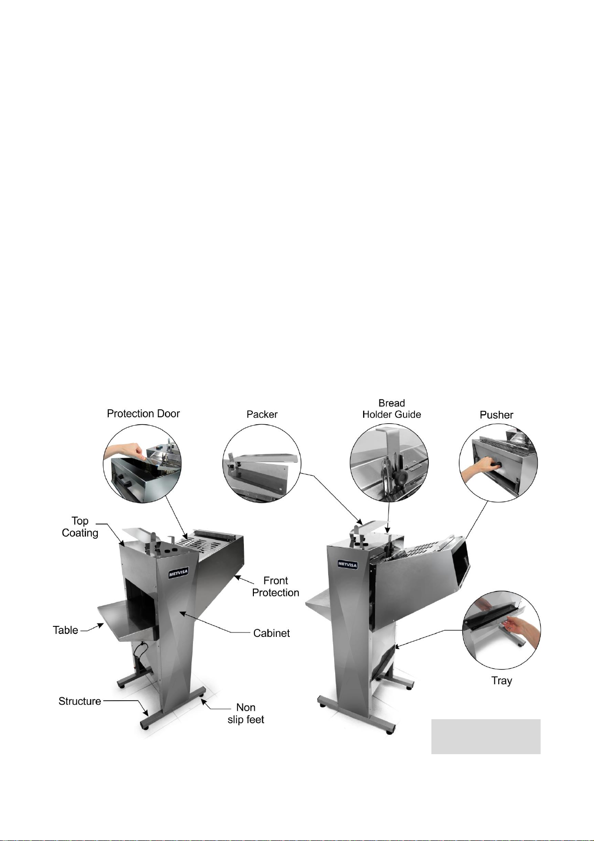
2.1 Main Components
For the equipment described in this manual, safety in use, cleaning, maintenance and
maximum hygiene are guaranteed by the project and special design of all parts and also by using
stainless steel and other materials suitable for contact with the bread.
The equipment was built with the following features:
• Protection door, front protection, top coating, structure, packer, table and tray are made of stainless
steel, which has superior corrosion resistance than other steels. It is a material resistant to the attack
of several corrosive agents;
• The blades are made of special steel, undergoing surface treatment that increases the material's
hardness and its resistance to wear. Its design and production guarantee perfect cutting precision;
• The structure and the pusher are made of SAE 1010/1020 carbon steel with electrostatic epoxy
paint, an excellent anti-corrosion protection that facilitates cleaning.
See the main components of the equipment below:
Note: For exploded view
with spare parts list, see
the annexes.

5
2.2 Technical Data
Model
Standard Measures
Length.xHt.xWidth
(mm)
Net weight
(kg)
Voltage
(V)
Rate
(A)
Useful Area
LengthxWidth
(mm)
FP12110M604
521x1365x915
72
110
3.7
360x150
FP12220M501
521x1365x915
72
220
2.2
360x150
FP12220M502
521x1365x915
72
220
2.2
360x150
FP12220M504
521x1365x915
72
220
2.2
360x150
FP12220M507
521x1365x915
72
220
2.2
360x150
FP12220M604
521x1365x915
72
220
2.1
360x150
Noise level (equipment with bread): 68 dB.
ATTENTION!
Characteristics like: model, serial number and voltage of the equipment are provided on the
label (figure below). Before installation, check that the power supply voltage of the
equipment corresponds to that of the mains
3. Installation
3.1 Equipment Layout
Connection to the electrical network and setup for operation must be carried out by a
qualified professional. Check if the equipment voltage is in accordance with the electrical network.
During installation, it is essential to make this manual available to the professionals who will
carry out the installation.
To ensure correct operation and safety, the equipment must be positioned in a sufficiently
large area, with a well level, dry and stable floor, away from heat sources and water taps, and in a
place where there is no heavy traffic of people. Install your equipment leaving a distance of at least 80
cm around it so that it has enough space for inspection, maintenance, cleaning and use.

6
ATTENTION!
The installation and the place where the equipment will be disposed must comply with the
norms of risk prevention and safety at work (regulatory norm in force in your country).
The manufacturer does not take responsibility for any direct or indirect damages caused by
non-compliance with these rules and other instructions presented in this manual.
3.2 Electrical Connection
The equipment is supplied with a power cord to plug into an electrical outlet. If the power
cord is damaged, it must be replaced with a new one. The exchange must be carried out by the
manufacturer, authorized agent or qualified person, in order to avoid risks.
The type of plug on the power cord varies by country. The installation of the equipment must
be carried out by a technician qualified for this function and observing the current regulations in the
country, especially with regard to grounding connection (if applicable).
Also included with the equipment is an equipotential grounding terminal, located at the rear
of the structure near the foot of the equipment.
The terminal identified in the figure aside is an additional protection to the
grounding that is provided for in the electrical network, it must be connected
to a grounding terminals, regardless of the connection to the electrical
network, and the other products that have accessible metallic parts, and that are stationary,
must also be connected to this bus as well as the service bench itself, if it is made of
metallic material. In this way, all these products will be under the same electrical potential,
avoiding undesirable leakage currents.
The equipment described in this manual is single-phase and single voltage, 110 V or 220 V.
If you need to change the voltage of your equipment, please contact the manufacturer or authorized
dealer.
ATTENTION!
Before turning on your equipment, always check that the mains supply voltage is the same
as the equipment's voltage.
The supply voltage of the equipment is 110 V or 220 V single-phase, as can be seen on the
voltage label affixed to the power cable or as indicated on the nameplate data label located
on the back of the equipment (see figure of this label in item 2.2 of this manual).
Make sure that the voltage of the electrical network where the equipment will be installed is
compatible with the voltage indicated on these labels.
For more details on the rest of the electrical part of the equipment, refer to the electrical
diagram in the manual annexes.

7
IMPORTANTE
The manufacturer does not take responsibility for any direct or indirect damages caused by
non-compliance with these rules and other instructions presented in this manual.
4. Equipment Use
4.1 Utility
This equipment is exclusively intended for slicing breads.
4.2 Commands
The equipment has an on/off button and a guide with a bread holder.
The power switch is located on the rear of the equipment, near the power cord. The guide
and the bread holder, on the other hand, are between the protection door and the upper covering.
See the description of each command below:
• On/Off Button –used to turn the equipment on and off. In position “1” it turns on, in position “0” it
turns off.

8
• Guide with Bread Holder –The guide slides up and down moving the bread holder, making it
possible to adjust the distance between the holder and the bread. So, the bread does not move from
the correct position during the process. To move the holder, follow the instructions below:
4.3 Operating Procedures
Before operating your equipment, make the perfect sanitation, especially of the components
that will come in contact with the bread. Do the cleaning with the equipment disconnected from the
mains. Follow the cleaning instructions in item 5 of this manual (below).
• Operation: The equipment can only be operated after verifying that the equipment voltage is in
accordance with the power supply network, if the equipment is positioned in an ideal location
(according to the guidelines in item 3.1), and if the tray is closed and locked, snapping the cutout
under the tray behind the screw.
Check the operating processes described below:
• Connect the power cord to the electrical network;

9
•After completing the process, turn off the equipment by pressing the power button in the "0"
position (off).
IMPORTANTE
It is recommended to place more than one bread at a time to speed up the process.
Never slice the bread while it is hot or raw. Wait until the bread is at room temperature and
properly baked.
ATTENTION!
Constantly empty the tray, thus preventing excess bread residues from overflowing and
falling to the floor, which could cause accidents and compromise the hygiene of the
establishment.
ATTENTION!
Never place your hands, fingers or objects (such as spoons and knives) on the cutting blade
while the equipment is on as this may cause serious injury.

10
ATTENTION!
If you notice that the equipment cannot slice the bread or it is stopping slicing, do not slice
breads that are still hot and do not press the pusher against the blades, as this will affect the
speed and performance of the motor, and the service life of the equipment.
Failure to follow these guidelines will be considered an unsafe act and abusive use of the
equipment.
Any irregularities, contact the authorized technical assistance closest to you.
5. Cleaning and Maintenance
5.1 Cleaning Procedures and Products Used
Your equipment was built with first-line materials, so use it properly and you will get great
satisfaction. Keep your equipment always clean and well-cared for, which will make it much more
durable.
A daily cleaning of the equipment must be carried out for good operation and durability
ATTENTION!
Before performing maintenance or cleaning, make sure that the on/off button is in position
”0” off and that the plug is disconnected from the mains.
ATTENTION!
Do not use water jet to clean the equipment.
IMPORTANTE
This equipment is not intended to be immersed in water for cleaning.
The detachable part (only the tray) must be removed from the equipment and washed with
soap and water or neutral detergent. Clean corners well, eliminating bread residue.
The rest of the equipment should be cleaned as many times as possible to prevent food
residues from drying out and sticking to the parts. For cleaning, dilute the soap or neutral detergent in
warm water and apply with a soft cloth. With a cloth dampened with water, rinse and then dry the
parts with a soft, dry cloth.
Never use abrasive products or sponges and substances that contain acids or chlorine to
clean metal parts, as they can scratch or damage the surface of the parts, causing corrosion points.
Do not pour water on the motor and electrical parts for cleaning, otherwise, starting it may cause an
electric shock or even burn the equipment.

11
ATTENTION!
It is extremely important that products used in cleaning ensure maximum cleanliness and
are non-toxic.
Dry the blade thoroughly. Moisture compromises the life of the blade and yield of the
cutting process.
ATTENTION!
Take care when cleaning near the blade, it is extremely sharp. Handle with care because this
may cause accidents. The same attention is paid to any other cutting component of the
equipment.
5.2 Maintenance and Procedures in Case of Breakdowns
The operator must be instructed to perform routine inspections, making minor adjustments,
cleaning and observing signs of breaches that may occur. Examples include: checking for strange
noise; loss of equipment power; the non-execution by the equipment of the service to which it is
proposed; among others. Actions like these are indispensable to ensure a longer equipment life.
ATTENTION!
When servicing (even minor adjustments), always disconnect the equipment from the mains.
It is recommended to carry out preventive maintenance every 6 months, checking and
adjusting clearances, cleaning internal parts, wear and tightening (tensioning) of the motor belt, etc.
When detecting broken or weakened parts, replace with original parts.
By performing preventive maintenance, you eliminate the inconvenience of getting the
equipment stopped when you need it most, reducing the cost of maintenance and reducing the risk of
accidents.
ATTENTION!
Preventive maintenance requires a trained professional or authorized technical assistance.
Make sure that the equipment is disconnected from the mains.
Whenever any item regarding the safety of the equipment (such as cleaning or maintenance) is
removed, reset it and confirm that it is performing its function correctly.
When you experience any malfunction or non-compliance, refer your equipment to the
nearest service center. See technical assistance on our website: www.metvisa.com.br

12
6. ANNEXES
Electrical Schematic –110 V or 220 V - 60 Hz
ATTENTION:For electrical installation, observe the current regulations in the country, especially
with regard to the grounding connection (if applicable).

13
Electrical Schematic –220 V –50 Hz
NOTE: In the electric schematic above, the White wires are represented by the pink color.
ATTENTION:For electrical installation, observe the current regulations in the country, especially
with regard to the grounding connection (if applicable).
14
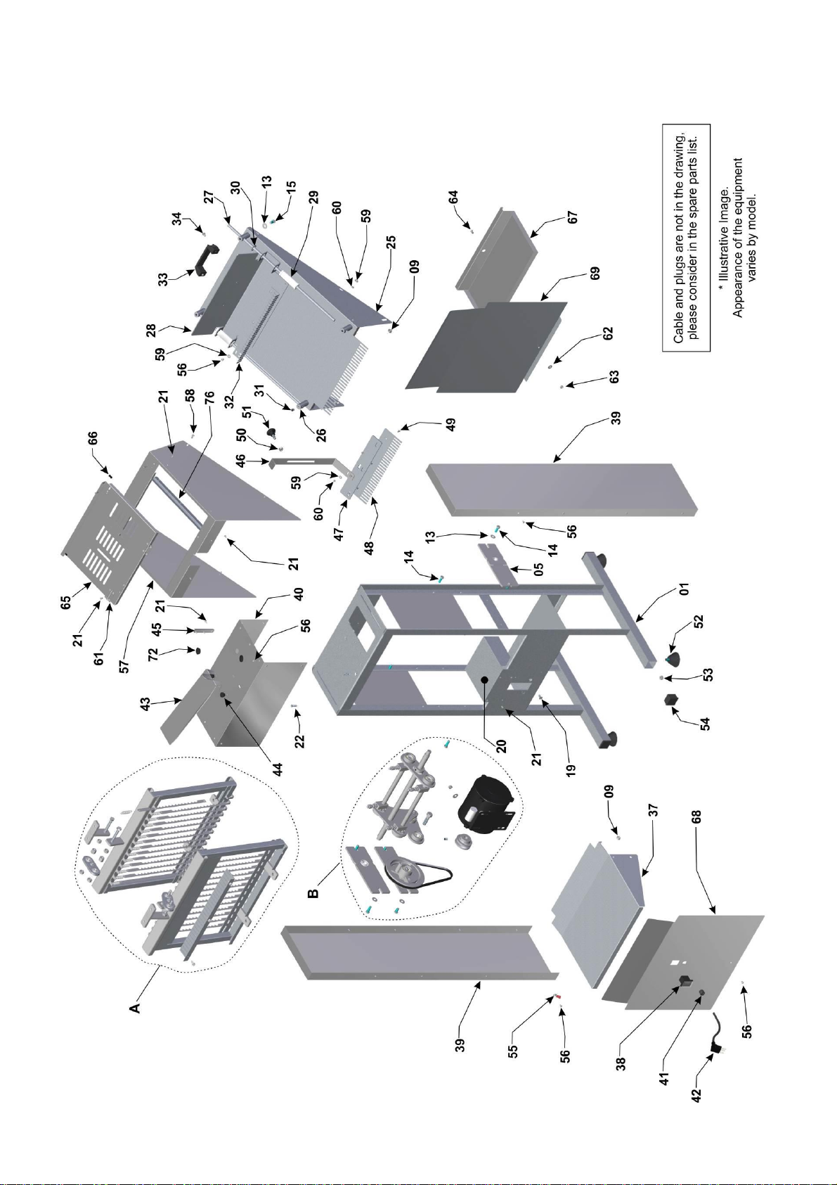
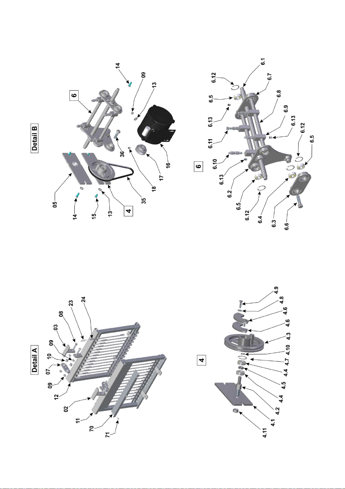
Exploded View
15
Exploded View

16
Spare Parts
Position
Code
Description
Quantity
1
ETR062
Complete Welded Structure
01
2
FXC002
Rear Articulator Fixer
01
3
FXC001
Front Articulator Fixer
01
4
CJT1057
Bearing and Pulley Set
01
4.1
MAC053
Pulley Bearing
01
4.2
EIX041
Pulley Shaft
01
4.3
POL017
Pulley
01
4.4
ROL003
Bearing ESF
02
4.5
SRO010
Bearing Separator
01
4.6
CTP003
Counterweight
02
4.7
APE001
Retaining Ring
01
4.8
ARL004
Flat Washer
02
4.9
PRS004
Hexagonal Screw
02
4.10
APE005
Retaining Ring
01
4.11
POS010
Hexagonal Nut
01
5
CJT1058
Bearing Side Assembly
02
6
CJT1059
Rod / Articulator / Axle Set
01
6.1
EIX207
Central Axis
01
6.2
BIL002
Double Rod
01
6.3
BIL003
Rod
01
6.4
ROL028
Bearing
01
6.5
ROL003
Bearing
05
6.6
EIX040
Rod Axle
01
6.7
ART003
Double Articulator
01
6.8
EIX042
Frame Axis
02
6.9
SBT382
Blade Frame Support
04
6.10
TRT009
Rod
04
6.11
POS004
Hexagonal Nut
16
6.12
APE001
Retaining Ring
06
6.13
PRN002
Allen Screw S/C
06
7
CJT700
Articulator Set
02
8
PRS012
Hexagonal Screw
04
9
POS004
Hexagonal Nut
20
10
POS014
Hexagonal Nut
04
11
CJT112
Rear Blade Frame
01
12
CJT111
Front Blade Frame
01
13
ARL003
Flat Washer
14
14
PRS006
Hexagonal Screw
08
15
PRS008
Hexagonal Screw
06
16
MTE214
Motor 1/4 HP 4P 127 V 60 Hz
01
MTE215
Motor 1/4 HP 4P 220 V 60 Hz
01
MTE035
Motor 1/4 HP 4P 220 V 50 Hz
01
17
PMT016
Pulley
01
18
PRN001
Allen Screw
01
19
PRC004
Flat Machine Screw
04
20
CRC061
Motor Protection
01
21
RBT004
Rivet
23
22
PRC003
Flat Machine Screw
04
23
MOL007
Blade Spring
28
24
LMT012
Blade
28
25
CLH002
Gutter
01
26
SBT266
Pusher Guide Support
04
27
GIA071
Pusher Guide
02
28
EPR011
Pusher
01
29
BGT050
Pusher Guide Bushing
02
30
APE004
Retaining Ring
02

17
Spare Parts
Position
Code
Description
Quantity
31
PRN002
Allen Screw
04
32
CRC906
Pusher's Comb
01
33
ACA009
Handle
01
34
PRR021
Round Machine Screw
02
35
COR006
Belt
01
36
EIX040
Rod Shaft
01
37
CJT081
Table
01
38
CHE016
On/Off Button
01
39
CRC545
Right and Left Side Protection
02
40
CRC909
Top Coating
01
41
TCE073
Cable Gland
01
42
CBE023
Cable Type 1 - FP12220M501
01
CBE029
Cable Type 2 - FP12220M502
01
CBE030
Cable Type 4 - FP12110M604
FP12220M604
.FP12220M504
01
CBE179
Cable Type 7 - FP12220M507
01
43
BDJ020
Packer
01
44
MNL014
Handle
02
45
AMP052
Holder Guide Support
02
46
GIA072
Holder Bread Guide
01
47
SBT274
Holder Bread Guide Support
01
48
CUP022
Comb Holder Plate
01
49
PRC009
Flat Machine Screw
04
50
POS015
Stainless Steel Hexagonal Nut
01
51
MNL008
Handle
01
52
PEP002
PVC Feet
04
53
POS003
Hexagonal Nut
04
54
SPT001
Plastic Shoe
04
55
TCE023
Equipotential Terminal
01
56
PRR017
Stainless Steel Round Machine Screw
34
57
PTC097
Front Protection
01
58
PRS045
Stainless Steel Hexagonal Screw
04
59
ARL008
Stainless Steel Flat Washer
11
60
POS016
Stainless Steel Hexagonal Nut
08
61
DBC004
Stainless Steel Hinge
02
62
ARL004
Flat Washer
01
63
POS021
Stainless Steel Hexagonal Nut
01
64
PRC005
Flat Machine Screw
01
65
PTA009
Front Protection Door
01
66
PTC102
Front Protection Door Protection
02
67
BDJ024
Tray
01
68
GAB229
Rear Structure
01
69
GAB126
Frontal Structure
01
70
SPD048
Blades Stainless Steel Separator
01
71
PRA007
Stainless Steel Self-Drilling Hexagonal Screw
03
72
BCH036
Round Cap
02
73
CBE033
Black Splice Electric Cable
01
74
CBE092
Power Cable Splice 200 mm Grounding
01
75
TCE013
Female Terminal
01

18
Notes

19

20
IMG-BRASIL Gastronomy Machinery Industry Ltda.
CNPJ 11.193.347/0001-14 - CREA 131726-3
Road. Antônio Heil - KM 23 Nº 5825 - Neighborhood: Limoeiro
ZIP CODE 88352-502 - Brusque - SC - Brazil
Phone/fax. +55 47 3251-5555 - Web Site: www.metvisa.com.br
This manual suits for next models
6
Table of contents
Other METVISA Kitchen Appliance manuals


