Meusburger GMT 6000 User manual

dpm Daum + Partner Maschinenbau GmbH · Am Lauerbühl 2 · D-88317 Aichstetten - 01.11.22
Operating Manual GMT 6000
- Precision cutting machine
Changes reserved! No. 300.00.00550

dpm Daum + Partner Maschinenbau GmbH · Am Lauerbühl 2 · D-88317 Aichstetten - 01.11.2022 2
Preface
The information contained in this manual ensures that the dpm
ejector cutting unit is operated safely, properly and efficiently.
Following the explanations, notices and regulations:
prevents hazards and faults,
reduces repair costs and downtimes
increases reliability and the service life
of the machine. The operator must ensure that persons tasked
with using, maintaining and repairing the dpm ejector cutting
unit read the manual. The manual must be kept at hand in the
place where the machine is used.
Not being familiar with or not observing this manual can
give rise to hazards to persons!
This manual must be read carefully before the ejector
cutting unit is commissioned. The instructions, particularly
the safety instructions, must be followed!
This manual applies only to the "ejector cutting unit“ indicated
on the cover page and specified in the section on "Suitability".
Before it is used outside its described field of application, it is
essential to consult
dpm Daum + Partner Maschinenbau GmbH
Am Lauerbühl 2
D - 88317 Aichstetten, Germany
Tel. +49 7565 94080 Fax. +49 7565 940850
Otherwise any warranty, liability and accessory liability claims
shall be void.
Copyright © 09 February 2018 by dpm Daum + Partner
Maschinenbau GmbH Realisation: dpm Daum + Partner
Maschinenbau GmbH
All rights to this manual are reserved, particularly the right of
reproduction and distribution as well as translation. No part of
the manual may be reproduced or electronically processed,
copied or distributed in any form (by copying, on microfilm or by
another means) without the prior written permission of Daum +
Partner.
Issue: 09 February 2018 Author: W. Ertel

dpm Daum + Partner Maschinenbau GmbH · Am Lauerbühl 2 · D-88317 Aichstetten - 01.11.2022 3
Contents
1Notes about the operating manual...................................................................................4
1.1 Note, terms, symbols................................................................................................4
1.2 Pictograms...............................................................................................................5
2Correct use in accordance to the instructions (intended use) ..........................................6
2.1 Use of the machine ..................................................................................................6
3Safety..............................................................................................................................7
3.1 Safety directives and regulations..............................................................................7
3.2 Safety hazards.........................................................................................................7
3.3 Safety symbols and safety markings of the ejector cutting unit.................................9
4Overall view...................................................................................................................10
4.1 Complete control unit .............................................................................................12
.........................................................................................................................................12
.........................................................................................................................................12
4.2 Complete linear unit –300.00.00403......................................................................13
4.3 Clamping prism –300.00.00382.............................................................................14
4.4 Support prism –300.00.00401...............................................................................15
4.5 Auflageprisma........................................................................................................15
4.5 Length adjustment –300.00.00174........................................................................16
4.6 Pivoting motor base................................................................................................17
.........................................................................................................................................17
.........................................................................................................................................17
4.7 Grinding spindle / cutting wheel –300.00.00409....................................................19
4.8 Grinding spindle / cup wheel –300.00.00407.........................................................20
4.9 Rocker bearing.......................................................................................................21
4.10 Spindle bearing –300.00.00359.............................................................................22
4.11 Technical Data.......................................................................................................23
5Operation......................................................................................................................24
5.1 Setting up the machine...........................................................................................24
5.2 Machine connections..............................................................................................25
5.3 Controls and displays.............................................................................................26
5.4Switching on...........................................................................................................29
5.5 Switching off...........................................................................................................29
5.6 Dressing the grinding wheel...................................................................................29
5.7 Inserting a workpiece .............................................................................................29
5.8Referencing "obtaining zero position".....................................................................30
5.9 Cut-off grinding.......................................................................................................30
5.10 Surface grinding.....................................................................................................30
5.11 Emergency stop.....................................................................................................31
5.12 Acknowledge the emergency stop..........................................................................31
6Care and maintenance..................................................................................................32
7Spare parts list..............................................................................................................36
8Zubehör.........................................................................................................................39
9Declaration of Conformity..............................................................................................40

dpm Daum + Partner Maschinenbau GmbH · Am Lauerbühl 2 · D-88317 Aichstetten - 01.11.2022 4
10 Fault report fax..............................................................................................................41
1 Notes about the operating manual
1.1 Note, terms, symbols
Safety Safety regulations for safe, risk-free use of the ejector
cutting unit
Operation Information about the suitability, use, function, operation,
variants and accessories
Commissioning Information on the operation of the machine
Control Explanation of the control elements, description of
handling
Maintenance Work that must be done for the purpose of safe operation,
to maintain functional capability and to avoid hazards or
faults
Faults Explanation of the causes of faults and how to remedy
them
Appendix Illustrations, standard maintenance instruction, sample of
an inspection report in accordance with the directives of
the employer's liability insurance association

dpm Daum + Partner Maschinenbau GmbH · Am Lauerbühl 2 · D-88317 Aichstetten - 01.11.2022 5
1.2 Pictograms
The machine and this manual carry labels that warn of hazards, stipulate or command
particular actions and point out special information. It is essential to follow the notices and
regulations that these highlight!
Danger!
Warning about a dangerous situation. There is a direct risk of a
serious accident is the regulations and instructions are not
observed!
Warning!
Warning about a possibly dangerous situation! Not following the
instruction can give rise to accident risks!
Caution!
Warning about a possibly dangerous situation or damage. Not
following the instructions can give rise to accident risks or damage
to the ejector cutting unit.
Command!
A particular action is stipulated! Not following the command can give
rise to a dangerous situation or damage!
Note!
Supplementary information about particular circumstances,
explanations, descriptions, cross references, explanations of special
activities or functional processes. Not following the instruction can
give rise to damage. There is no accident risk.

dpm Daum + Partner Maschinenbau GmbH · Am Lauerbühl 2 · D-88317 Aichstetten - 01.11.2022 6
2 Correct use in accordance to the instructions (intended use)
2.1 Use of the machine
Machine tool for cutting and surface grinding of cylindrical and stepped ejector pins, flat
ejectors, profile stamps, punching dies, ejector bushes etc. The grinding wheels are driven
by two three-phase asynchronous motors with squirrel-cage rotors by a toothed belt drive.
The force exerted by the workpiece on the grinding wheel is always radial. The cup wheel
can be aligned by a puller diamond and set with an adjusting screw until the wear limit is
reached. The workpiece is held in place by a spring clamping prism and positioned with a
stop. A linear unit with screw spindle adjustment and visual digital output facilitates the exact
(0.01 mm) positioning/advance of the workpiece before cutting (separation) and subsequent
surface grinding.

dpm Daum + Partner Maschinenbau GmbH · Am Lauerbühl 2 · D-88317 Aichstetten - 01.11.2022 7
3 Safety
3.1 Safety directives and regulations
The following general safety regulations must be followed:
Commissioning, operation and maintenance only after briefing and
instruction by the owner and knowledge of the operating
manual.
Commissioning, operation and maintenance only by trained and
qualified personnel (protective goggles and safety shoes are
mandatory)
When switching on the machine, the direction of rotation of the cup
wheel must be clockwise and that of the cutting wheel must be
counter-clockwise, see also instructions under 5.2 Connections of
the machine
Only switch on once you have checked the safety devices function
correctly.
Do not tamper with any safety devices or bypass, deactivate or
remove them.
The accident prevention regulations must be observed, and all
working methods that can jeopardise work safety are prohibited.
3.2 Safety hazards
Potential hazards if the operating manual is not followed:
If the machine is not operated, maintained or repaired in accordance
with the safety regulations, or if it is operated improperly or misused,
the result is
Hazards to the health of operating personnel
Hazards to the machine and other property belonging to the
operator
Impairment of the machine's efficient functioning.
If the regulations laid down in the operating manual are not observed,
the manufacturers shall not be liable for the resulting damage and
consequential losses!

dpm Daum + Partner Maschinenbau GmbH · Am Lauerbühl 2 · D-88317 Aichstetten - 01.11.2022 8
Safety hazards can occur from:
Working at the machine without a protective cover on the
grinding wheel, (unauthorized changes to the safety devices
are not permitted).
The two grinding wheels rotating in the incorrect direction
The rotating grinding wheels when working at the machine
(there is a risk of clothes, long hair or gloves being pulled into
the machine).
Force applied to the grinding wheels in the axial direction.
(There is a risk of breakage of the grinding wheels).
Operating the rocker mechanism (there is a risk of crushing
between the rocker and its base).
Working on the machine without protective goggles (danger
from flying metal chips and grinding dust).
Removing the cut-off workpiece parts (risk of burning)
Parts can be thrown out if the grinding wheels are defective.
(risk of injury).
Inserting the shaft into the spring prism (risk of crushing
fingers).
Risk from electrostatic charging of components, personnel
touching contact charged parts.
Working at the electronic box or motor housing by touching
live parts during operation. Risk from damaged lines or
cables. Only trained electricians may carry out such work.
Do not operate the machine in hazardous areas.
Switching on the machine with the workpiece inserted
Transportation of the machine - personal safety measures
appropriate to the total weight of the machine must be taken.
Additionally, the personnel must be informed about any loose
or moving parts of the machine before transport. (Only
trained and instructed personnel are permitted to transport the
machine).
The main switch must be switched off for maintenance,
inspection or cleaning of the machine.

dpm Daum + Partner Maschinenbau GmbH · Am Lauerbühl 2 · D-88317 Aichstetten - 01.11.2022 9
3.3 Safety symbols and safety markings of the ejector cutting unit
1
Mandatory
instruction
Disconnect first, then work on the electrical
installation.
2
Mandatory
instruction
Wear ear protection, Wear protective goggles, First
read the operating manual, then activate!
4
Warning
There is a risk of electric shock

dpm Daum + Partner Maschinenbau GmbH · Am Lauerbühl 2 · D-88317 Aichstetten - 01.11.2022 10
4 Overall view
1) 300.00.00398 (1x)
Base
5) 060.30.905 (1x)
Glass scale MKT 37
9) 300.00.00392 (1x)
Disc cover
13) 050.01.2971
Cup wheel
2) 300.00.00370 (1x)
Complete control cabinet
6) 300.00.00174 (1x)
Longitudinal adjustment
(cup wheel)
10) 300.00.00392 (1x)
Disc cover
14) 050.01.2972
Cutting wheel
3) 300.00.00403 (1x)
Linear unit
7) 050.01.2744 (1x)
Handle
11) 300.00.00387 (1x)
Holding rail for handle
4) 300.00.00462 (1x)
Cover
8) 300.00.00390 (1x)
Cover for complete
grinding wheel
12) 050.01.2953
Insulation for cover
dpm Daum + Partner Maschinenbau GmbH · Am Lauerbühl 2 · D-88317 Aichstetten - 01.11.2022 11
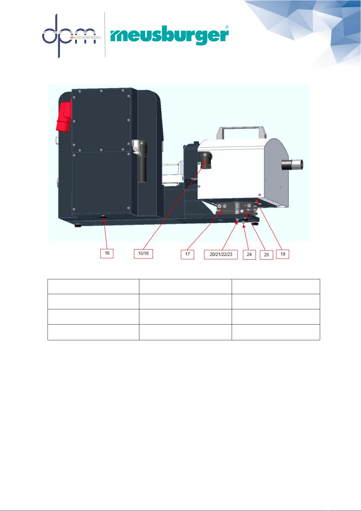
15) 050.01.2750 (1x)
Corrugated pipe fitting 90°
19)300.00.00433 (1x)
Complete drive console
23) 300.00.00437 (2x)
Bracket
16) 050.01.2886 (4x)
Rubber-metal stop
20) 300.00.00452 (1x)
Spring retainer, long
24) 300.00.00451 (1x)
Spring retainer, short
17) 300.00.00359 (1x)
Adjustable spindle mount
21) 050.01.2928 (2x)
Pressure spring
25) 300.00.00372 (2x)
Adjusting block
18) 060.80.279 (1x)
Counter nut M32x1.5
22) 300.00.00436 (2x)
Spring bearing
dpm Daum + Partner Maschinenbau GmbH · Am Lauerbühl 2 · D-88317 Aichstetten - 01.11.2022 12
6
11
14
15
12
17
18
19
20
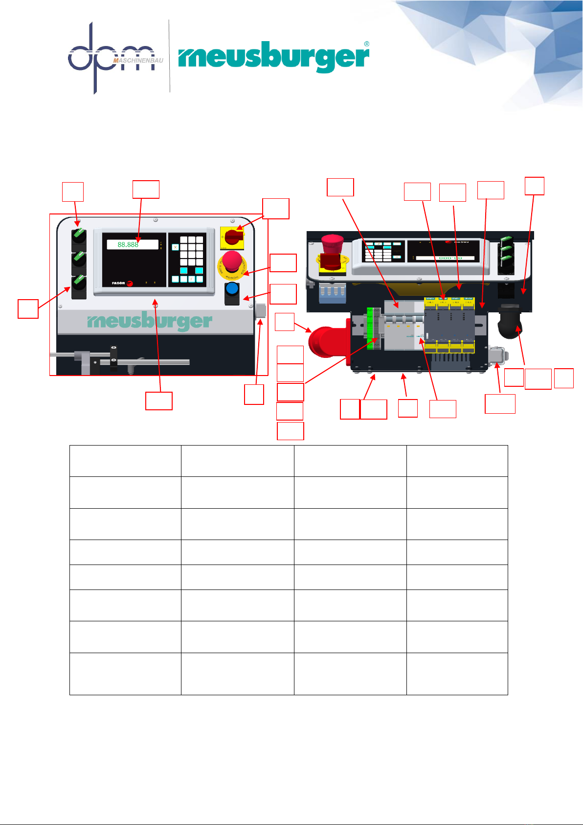
4.1 Complete control unit
1) 300.00.00355 (1x)
Bottom cover
9) 300.00.00360 (1x)
Control cabinet housing
17) 060.80.008-200 (1x)
DIN rail 35x7.5
25) E061.03.00160 (2x)
Battle plate, grey
2) 300.00.00367 (1x)
Electrics box cover
10) E061.04.00001 (1x)
Mounting case, angled
18) E061.12.00303 (1x)
3-pin circuit breaker
26) E061.03.00150 (2x)
4-wire circuit terminal
2,5mm²
3) 050.01.2750 (1x)
Corrugated pipe fitting
90°
11) 061.13.00262 (1x)
Emergency stop
pushbutton
19) E061.24.14000 (1x)
Safety relay
27) E061.03.09050 (1x)
Group tag holder
4) 061.13.00384 (3x)
Iluminated toggle switch
12) 060.30.904 (1x)
Innova Display
20) E061.24.14001 (3x)
Sirius motor starter
5) 061.51.12111 (1x)
Cable gland
13) 300.00.00368 (1x)
Dichtung El.-Box
21) E061.12.00002 (1x)
1.pin circuit breaker
6) E061.04.70000 (1x)
CEE-plug
14) E061.09.00003 (1x)
Main / emergency-stop
switch
22) 300.00.00426 (1x)
Operating Panel, angled
7) 050.01.2751 (1x)
Corrugated pipe
PUR NW 29
15) 061.13.01024 (1x)
Illuminated pushbutton,
blue
23) E061.03.09000 (2x)
End clamp TS 35
8) 061.52.02040 (4x)
Tag labelling
16) 060.80.279 (1x)
Counter Nut M32x1.5
24) E061.03.00154 (2x)
4-wire circuit terminal
2,5mm²
1
2
3
5
7
8
10
13
16
21
22
23
24
25
26
27
4
9
dpm Daum + Partner Maschinenbau GmbH · Am Lauerbühl 2 · D-88317 Aichstetten - 01.11.2022 13
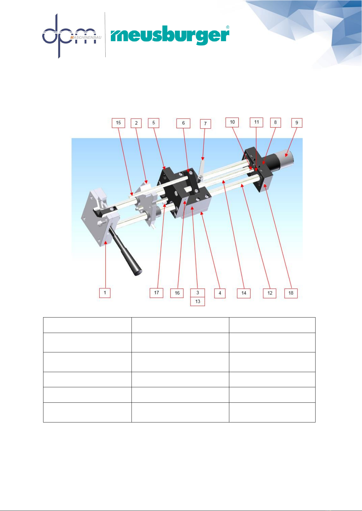
4.2 Complete linear unit –300.00.00403
1) 300.00.00382 (1x)
Clamping prism
7) 050.01.2713 (1x)
Clamping lever
13) 050.01.2718 (4x)
Ball lining Ø16
2) 300.00.00401 (1x)
Support prism
8) 300.00.00379 (1x)
Carriage guide bracket, outer part
14) 050.01.2715 (1x)
Hardened precision shaft
Ø12h6
3) 300.00.00173 (1x)
Carriage base
9) 300.00.00174 (1x)
Length adjustment
15) 050.01.2716 (1x)
Hardened precision shaft
Ø8h6
4) 300.00.00386 (1x)
Monitoring car holder
10) 300.00.00466 (1x)
Shaft for length adjustment
16) Threaded pin (1x)
ISO 4026-M6x16
5) 300.00.00166 (1x)
Carriage face plate
11) 300.00.00009 (1x)
Carriage guide bracket, inner part
17) Hardened cylinder pin (1x)
ISO 8734-8x50
6) 300.00.0456 (1x)
Stop part
12) 050.01.2714 (2x)
Hardened precision shaft
Ø16h6
18) Threaded pin (6x)
ISO 4026-M6x8

dpm Daum + Partner Maschinenbau GmbH · Am Lauerbühl 2 · D-88317 Aichstetten - 01.11.2022 14
4.3 Clamping prism –300.00.00382
1) 300.00.00380 (1x)
Clamping prism base plate
5) 050.01.2770 (1x)
Dressing diamond
9) Hardened cylinder pin (2x)
ISO 8734-5x24
2) 300.00.00162 (1x)
Push-pull device guide
6) 050.01.2712 (1x)
Cone handle
10) Hardened cylinder pin (1x)
ISO 8734-5x10
3) 300.00.00161 (1x)
Push-pull device
7) 300.00.00036 (1x)
Lever
11) Threaded pin (1x)
ISO 4026-M5x16
4) 300.00.00163 (1x)
Support
8) 050.01.2892 (1x)
Control spring Ø10x35.3xØ1.4
12) Threaded pin (1x)
ISO 4026-M5x16
dpm Daum + Partner Maschinenbau GmbH · Am Lauerbühl 2 · D-88317 Aichstetten - 01.11.2022 15
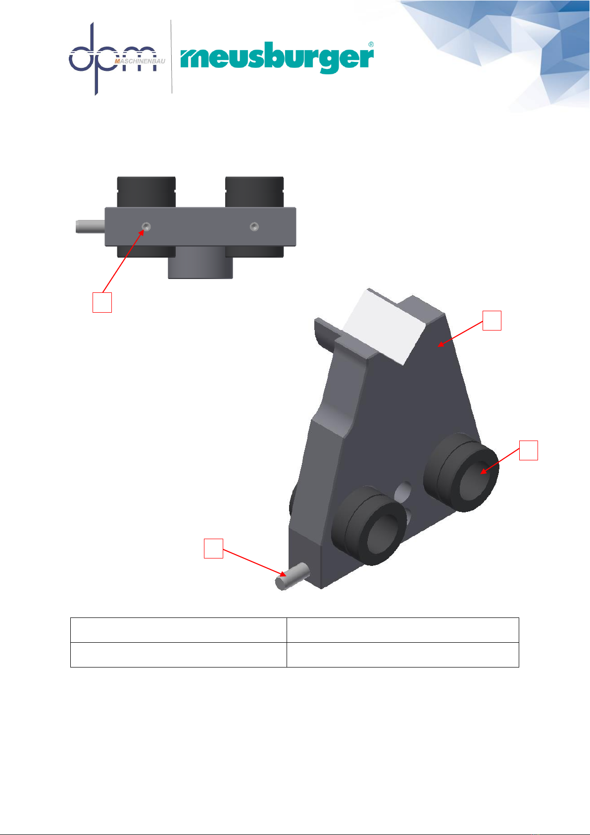
4.4 Support prism –300.00.00401
4.5 Auflageprisma
1) 300.00.00402 (1x)
Support prism plate
3) Hardened cylinder pin (1x)
ISO 8734-6x20
2) 050.01.2718 (2x)
Bushing
4) Hexagon socket set screw with truncated cone (2x)
ISO 4026 M5x8 –45 H 2x
2
3
1
4
dpm Daum + Partner Maschinenbau GmbH · Am Lauerbühl 2 · D-88317 Aichstetten - 01.11.2022 16
4.5 Length adjustment –300.00.00174
1) 300.00.00175 (1x)
Adjustment bush
5) Retaining ring (1x)
DIN 471 - 15x1
9) Retaining ring (1x)
DIN 472 - 15x1
2) 300.00.00011 (1x)
Support
6) Axial deep groove ball bearings (2x)
050.31.910 (Ø15 x Ø28 x 9)
3) 300.00.00014 (1x)
Washer disc
7) 050.01.2899 adjusting washer (1x)
Ø15 x Ø28 x 1
4) 300.00.00396 (1X)
Washer
8) Threaded pin (3x)
ISO 4026-M4x4

dpm Daum + Partner Maschinenbau GmbH · Am Lauerbühl 2 · D-88317 Aichstetten - 01.11.2022 17
4.6 Pivoting motor base
1) 300.00.00409 (1x)
Cutting wheel grinding spindle
7) 300.00.00194 (1x)
Pulley T5/Z72
13) 300.00.00352 (1x)
angel f. adjustment
2) 300.00.00407 (1x)
Cup wheel grinding spindle
8) 300.00.00186 (1x)
Pulley T5/Z48
14) 300.00.00412 (1x)
Stop ring
3) 060.07.051 (1x)
Three-phase asynchronous motor
0.75 kW
9) 300.00.00427 (1x)
Mounting flange f. motor kl.
15) 300.00.00423 (1x)
Perforated sheet
4) 060.07.050 (1x)
Three-phase asynchronous motor
0,37 kW
10) 300.00.00428 (1x)
Mounting flange f. motor gr.
16) 300.00.00063 (1x)
Delivery agent
5) 050.01.2747 (1x)
Toothed belt T5 Z78
11) 300.00.00195 (1x)
Connecting washer
17) 300.00.00235 (1x)
Engine cover
6) 050.01.2746 (1x)
Toothed belt T5 Z90
12) 300.00.00187 (1x)
Connecting washer
18) 050.01.2748 (2x)
Scraper Ø40xØ48,6x7
19) 300.00.00094 (1x)
Scraper Ø14 x 1 x 160
2
14
1
3
4
5
6
7
10
11
13
15
17
16
8
9
12

dpm Daum + Partner Maschinenbau GmbH · Am Lauerbühl 2 · D-88317 Aichstetten - 01.11.2022 18
Info! M6 bolts glued with VBA 2M70 (Meusburger)!
Cylinder head screw M6 14Nm tightening torque!

dpm Daum + Partner Maschinenbau GmbH · Am Lauerbühl 2 · D-88317 Aichstetten - 01.11.2022 19
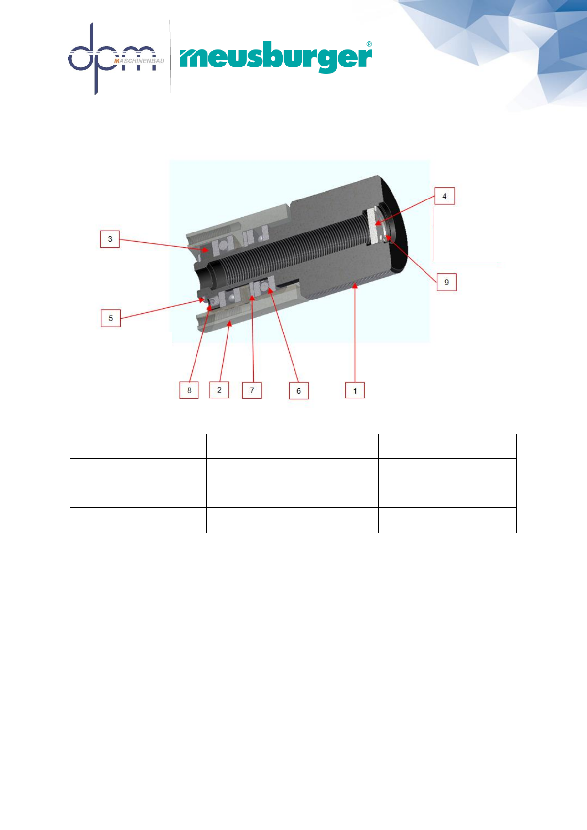
4.7 Grinding spindle / cutting wheel –300.00.00409
1) 300.00.00408 (1x)
Grinding spindle sleeve
5) 300.00.00055 (1x)
Washer
9) 300.00.00182 (1x)
Toothed belt pulley T5 Z19
2) 300.00.00048 (1x)
Grinding spindle shaft
6) Fitting key (1x)
DIN 6885 A4x4x18
10) Cylinder head bolt
ISO 4762 M6x16-12.9 (1x)
3) 300.00.00393 (1x)
Clamping nut
7) 050.31.015 (2x) deep groove ball
bearings
DIN 625 SKF 6001-2RS1
11) stop ring (1x)
300.00.00412
4) 300.00.00050 (1x)
Disc flange, inside
8) 300.00.00052 (1x)
Threaded ring
5
6
7
11
1
8
10
3
4
9
2
dpm Daum + Partner Maschinenbau GmbH · Am Lauerbühl 2 · D-88317 Aichstetten - 01.11.2022 20
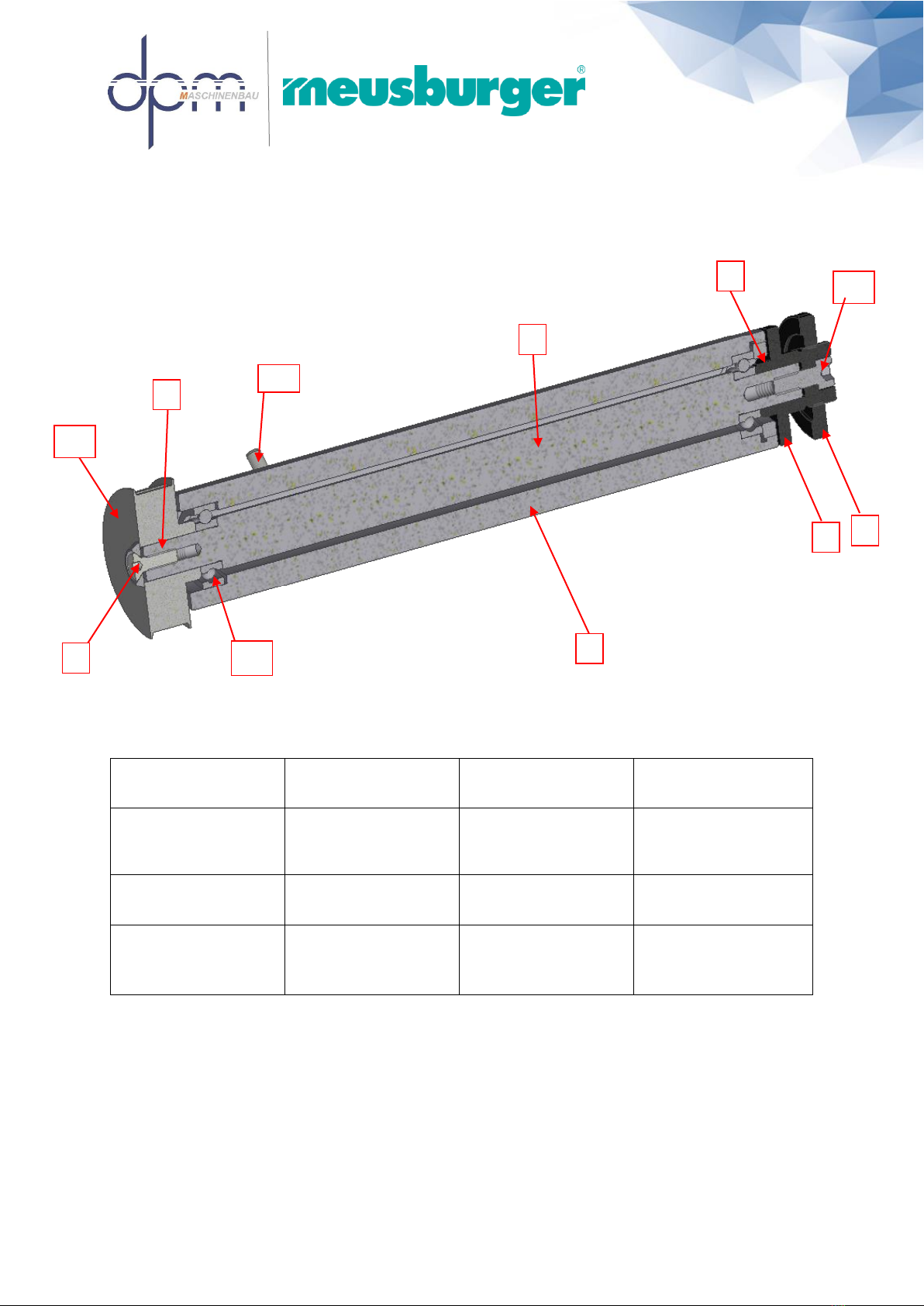
4.8 Grinding spindle / cup wheel –300.00.00407
1) 300.00.00045 (1x)
Grinding spindle sleeve
5) 300.00.00052 (1x)
Threaded ring
9) 300.00.00185 (1x)
Toothed belt pulley
T5 Z30
2) 300.00.00406 (1x)
Grinding spindle shaft
. 6) 300.00.00055 (1x)
Washer
10) Cylindrical pin
hardened
(ISO 8734-5x16) (1x)
3) 300.00.00223 (1x)
Disc flange inside,
Left-handed
7) Adjusting spring (1x)
DIN 6885 A4x4x18
11) 050.01.2887 (1x)
ISO 4762 M6x16-12.9
Left-hand thread
4) 300.00.00394 (1x)
Clamping nut,
left-hand thread.
8) 050.31.015 (2x)
Deep groove ball
bearings DIN 625
SKF 6001-2RS1
1
2
3
4
5
6
11
7
8
9
10
Other manuals for GMT 6000
1
Table of contents
Other Meusburger Cutter manuals

Popular Cutter manuals by other brands


Stryker
Stryker 0940-000-000 Instructions for use

KEENCUT
KEENCUT Evolution3 FreeHand user guide

Current Tools
Current Tools 754 Operating, Maintenance, Safety and Parts Manual

Makita
Makita DCS553 instruction manual

EINHELL
EINHELL 43.012.50 operating instructions

Xyron
Xyron Personal Cutting System None user manual