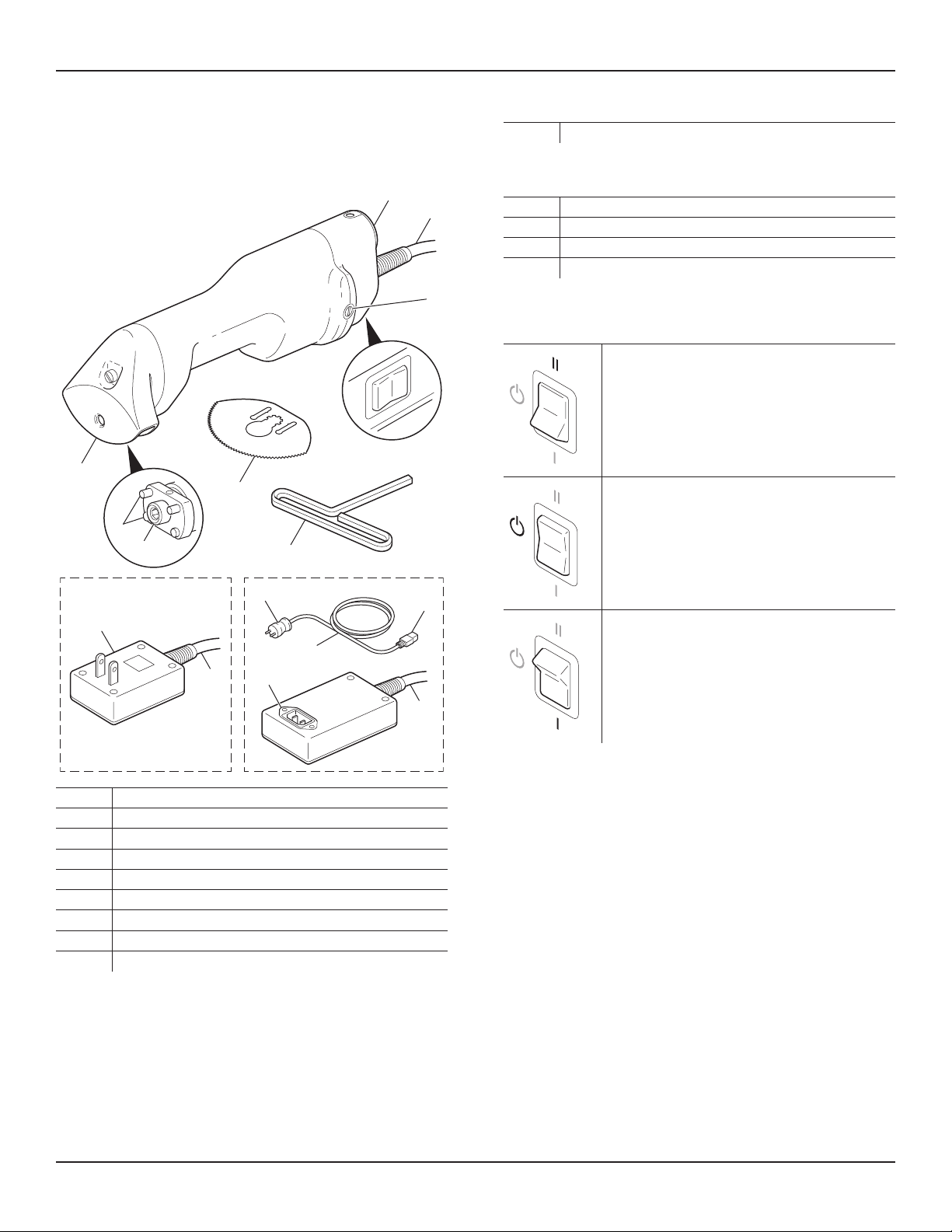
0940-001-025 Rev-L EN
www.stryker.com 7
Cleaning
WARNINGS:
▪ ALWAYS disconnect the power cord plug from the facility power outlet or
CastVac power outlet before cleaning the equipment. Failure to comply
may cause fire, electric shock, or injury.
▪ Upon initial receipt and before each use, clean and disinfect the
equipment as indicated.
▪ DO NOT sterilize the equipment.
▪ DO NOT immerse or soak the equipment in liquid. DO NOT flush the
internal vacuum line with liquid. DO NOT allow moisture or liquid to soak
into electrical plugs, receptacles, or openings. Moisture or liquid inside the
equipment may create an unsafe electrical condition, cause corrosion,
and/or damage the electrical and/or mechanical components.
▪ Before each use, make sure the equipment is completely dry. DO NOT
use any equipment if moisture is present.
▪ DO NOT use solvents, lubricants, or other chemicals, unless otherwise
specified.
To Clean the Equipment
1. Disconnect the power cord plug from the facility power outlet or CastVac
power outlet.
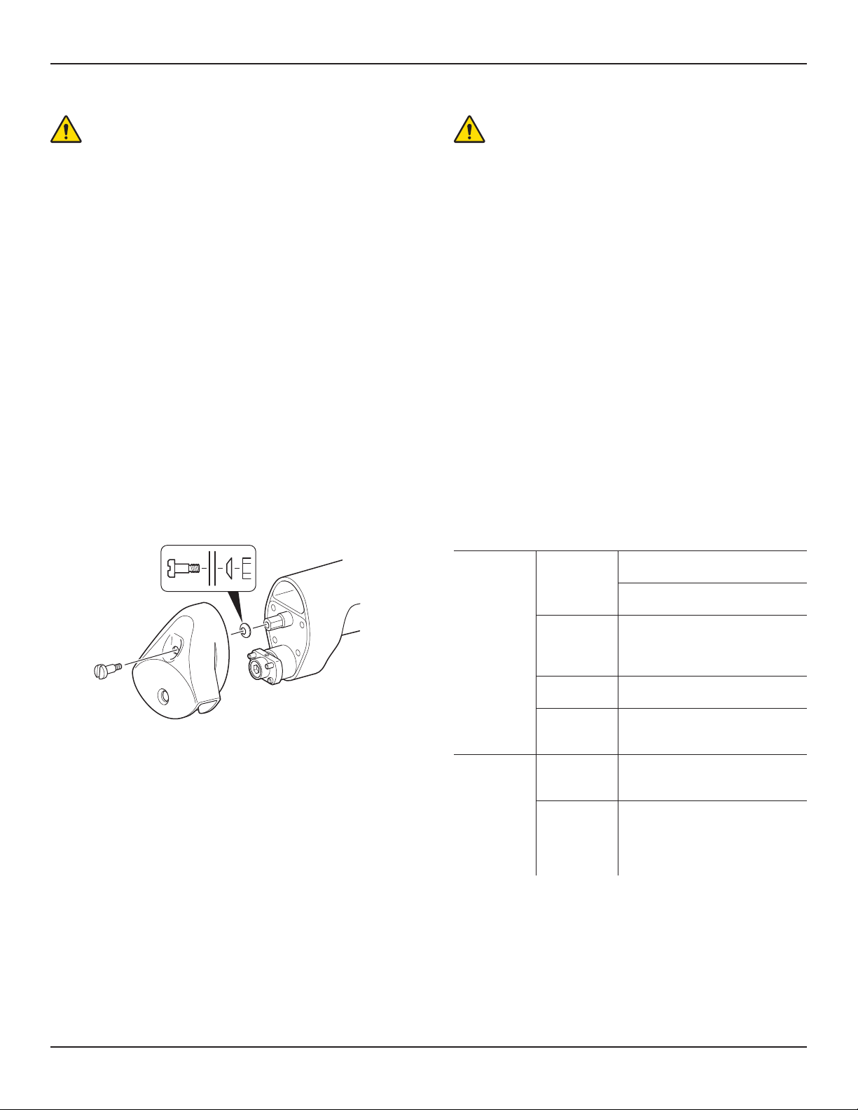
2. If the vacuum hood is blocked with debris, perform the following steps:
2.1. Use a standard slotted screwdriver to remove the captive screw,
Belleville washer, and vacuum hood.
2.2. Remove any blockage and wipe away the debris.
2.3. Reinstall the vacuum hood and Belleville washer, and securely
tighten the captive screw.
NOTE: Make sure the Belleville washer is oriented correctly during
reassembly. See the illustration above.
3. Wipe the external surfaces of the equipment with a soft cloth moistened
with a non-abrasive, mild detergent and water.
4. Thoroughly dry the equipment with a soft, absorbent cloth.
To Disinfect the Equipment
1. Wipe the external surfaces of the equipment with a soft cloth moistened
with isopropyl alcohol. Blades can be disinfected with a standard
disinfectant.
2. Thoroughly dry the equipment with a soft, absorbent cloth.
Inspection, Testing, and Maintenance
WARNINGS:
▪ Only individuals trained and experienced in the maintenance of reusable
medical devices should inspect, test, and maintain this equipment.
▪ DO NOT disassemble or service this equipment, unless otherwise
specified. Failure to comply may cause fire, electric shock, or injury.
▪ ALWAYS disconnect the power cord plug from the facility power outlet or
CastVac power outlet before performing maintenance procedures on the
equipment. Failure to comply may cause fire, electric shock, or injury.
▪ Only the components listed in the Inspection, Testing, and Maintenance
section are serviceable.
▪ When servicing or maintaining this equipment, use only Stryker-approved,
identical replacement parts.
▪ DO NOT use the Cast Cutter if the leakage current exceeds the
appropriate specification. See the Specifications section.
NOTES:
▪ The Cast Cutter has a lifetime lubrication system. No additional lubrication
is required.
▪ Calibration adjustments for the Cast Cutter were made during
manufacturing. No additional calibration is required.
▪ Maintenance documentation for this equipment is available upon request
to Stryker-authorized service personnel only.
▪ For service, contact your Stryker sales representative or call Stryker
customer service. Outside the US, contact your nearest Stryker subsidiary.
INTERVAL ACTION INSPECTION CRITERIA
Upon initial
receipt and
before each
use.
Inspect the
equipment.
If damage or excessive wear is
apparent, contact Stryker for repair.
If any components are loose or
missing, contact Stryker for repair.
Inspect the
power cord
and/or power
source cord.
If cracks, cuts, or damage is apparent,
contact Stryker for repair.
Inspect the
blade.
If the blade is dull, replace the blade.
See the Instructions section.
Operate the
equipment.
If unusual sound, excessive noise, or
vibration is apparent, contact Stryker
for repair.
Annually. Actuate the
function switch
five times.
If the equipment does not operate
normally, contact Stryker for repair.
Use a
tachometer
to determine
the operating
speed.
If the equipment does not operate at
the proper speed, contact Stryker for
repair. For speed information, see the
Specifications section.