Meusburger H 4062 User manual

Meusburger Georg GmbH & Co KG | Kesselstr. 42 | 6960 Wolfurt | Austria
T +43 5574 6706-0 | sales@meusburger.com | www.meusburger.com
1. User instructions:
1.1. Purpose and validity of document:
This document contains the information that is necessary for the proper use of the products described therein. It is intended for
use by technically qualied personnel. Qualied personnel are persons who, by virtue of their training, experience and instruction,
in conjunction with their knowledge regarding the relevant standards, provisions, accident prevention regulations and operating
conditions, have been authorised by the Plant Safety Ocer to carry out the required activities in order to ensure that potential
hazards are recognized and avoided.
1.2. Visual representation of safety instructions:
Wear safety footwear:
Risk of crushing!
Trip hazard:
2. General safety instructions:
2.1. Intended use:
The assembly table is used in order to facilitate the installation and maintenance work on moulders moulds, die cast and
moulds and punching tools. It is only intended for moulds and tools that possess sucient stability by virtue of the ratio of their
footprint-to-height ratio. Proper use of the assembly table also includes compliance with the instructions regarding safety,
operation, maintenance and servicing which form part of this user manual.
2.2. Technical specications:
Description Unit H 4062/496/1156 H 4062/796/1496 H 4062/996/1846
Dimensions (w x l x h) [mm] 526 x 1186 x 860 826 x 1526 x 880 1026 x 1876 x 700
Unladen weight [kg] 320 700 1200
Maximum connection pressure [bar] 6 6 8
Maximum load on the table [kg] 3000 3000 5000
Maximum load on the moving plates (per plate) [kg] 2000 2000 2500
Maximum tool size [mm] Width 500
Height 1000
Width 800
Height 1000
Width 900
Height 1300
Maximum tool overhang over moving plates [mm] 80 on all sides 100 on all sides 50 on all sides
Attention
User manual – Assemby table H 4062

Meusburger Georg GmbH & Co KG | Kesselstr. 42 | 6960 Wolfurt | Austria
T +43 5574 6706-0 | sales@meusburger.com | www.meusburger.com
2.3. Foreseeable misuse:
If incorrectly assembled (in a non-horizontal position), stability is
not guaranteed under high load conditions (see 5). Large mould
halves which, as a result of their footprint-to-height ratio, do not
possess sucient stability, must be secured using the
anti-tipping brackets supplied (see 3.2). Make sure that the
underside of the mould or die half rests completely on the
support plate so that there is no point load. The maximum tool
size and the maximum weight must not be exceeded. The
maximum tool overhang must be adhered to, in order to prevent
the tool Support plate from tipping. The assembly table must
never be left unsupervised while switched on.
2.4. Residual risks:
Please be aware of the trip hazard caused by the protruding
feet of the assembly table with base frame. In users must be
aware of the risk that their ngers may be crushed by the raised
edges when the moving plates are in operation.
2.5. Duties of the operator:
The operator is obliged to instruct operating personnel with
regard to the safe and proper handling, maintenance, servicing
and appropriate operation of the assembly table. The operator
must prove that the assembly table has been erected in
accordance with the instructions.
2.6. Duties of the user:
Any person operating the assembly table must have read this
user manual. Proper protective clothing must be worn and the
safety instructions must be adhered to.
2.7. User qualications:
The assembly table must only be used by specialised personnel
qualied who have read the user manual. Trainees must
operate the assembly table under supervision only.
2.8. Personal protective equipment:
All users are obliged to wear protective gloves and class 2 or
higher safety footwear (non-slip soles and protective toecaps).
2.9. Safety and protection devices:
In order to prevent the slippage of the Support plate beyond the
edge of the table surface, raised edges have been tted around
the entire edge of the table. Checks should be carried out on a
regular basis to make sure these are still rmly attached.

Meusburger Georg GmbH & Co KG | Kesselstr. 42 | 6960 Wolfurt | Austria
T +43 5574 6706-0 | sales@meusburger.com | www.meusburger.com
3. Description of machine:
3.1. Versions
Mat.: 1.1730
n* max. kg* p* [bar] b1 l1 l2 h b l No.
23000 6 346 266 296 850 496 1156 H 4062/496/1156
2 596 346 396 796 1496 H 4062/796/1496
1 5000 8 796 466 496 660 996 1846 H 4062/996/1846
* n) number of drawers | max. kg) maximum load capacity | p) operating pressure
3.2. Sub-assemblies and components:
1. Base-plate tted
2. Base frame
3. Tool cabinet
4. Moveable plates
5. Anti-tilt brackets
6. Adjustable feet
7. Securing bolt for tool cabinet
h
n
bb1
l1
l2
l
7
4
5
3
2
6
1

Meusburger Georg GmbH & Co KG | Kesselstr. 42 | 6960 Wolfurt | Austria
T +43 5574 6706-0 | sales@meusburger.com | www.meusburger.com
3.3. Accessories:
4 eye bolts 2 xing brackets
2 xing brackets
Copper mallet
Multi oil VMM 4
Spirit level
4. Transportation:
The assembly table can be transported using a forklift truck,
as the base frame has been congured in such a way that the
forklift truck can drive underneath the table without hindrance.
The table can also be lifted by means of the eye bolts supplied.
Transportation by crane (eye bolts) must only take place if the
moveable plates have been removed.
5. Installation and commissioning:
The assembly table must be placed so that there is at least
0.5 m of free space on all sides. In order to guarantee the
stability of the table, it must be placed on a rm surface in a
horizontal position to be veried using the spirit level supplied.
The feet of the table can be adjusted for this purpose.
In order to avoid exceeding the maximum air pressure, a
pressure regulator (not included in the delivery) must be
installed upstream of the compressed air connector of the
assembly table, before commissioning. In order to ensure that
the compressed air supply can be shut o, a stop-cock (not
included in the delivery) must be tted upstream of the
compressed air connector of the assembly table.
5.1. Compressed air supply/pneumatics connection plan:
The connector to the assembly table is a coupler with d1:9.
shut-o valve
(main switch)
manual slide valves
on the table
support plates
(consumers)
H 4062 Assembly table
to be installed by the
operator
pressure regulator
with manometer
pneumatic source
Meusburger Georg GmbH & Co KG | Kesselstr. 42 | 6960 Wolfurt | Austria
T +43 5574 6706-0 | sales@meusburger.com | www.meusburger.com
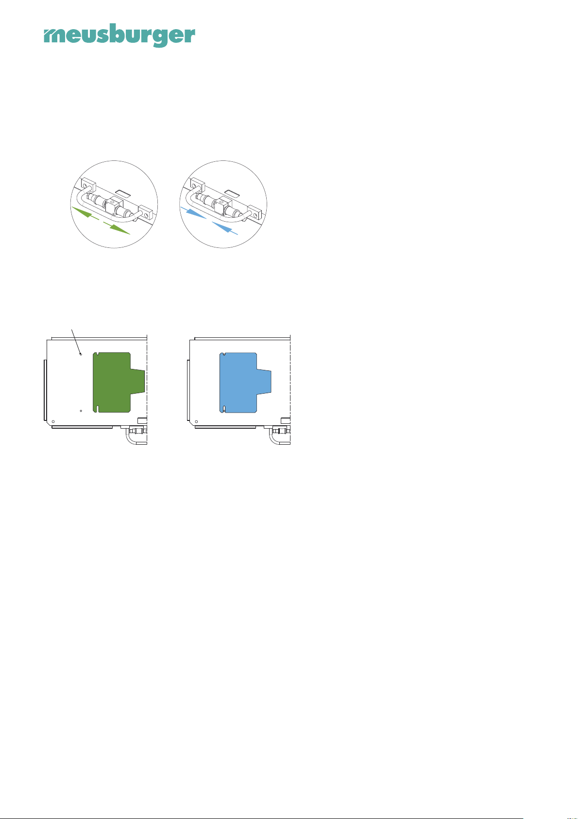
6. Operation (Normal operation):
6.1. Operating and display elements:
Both support plates of the mould can be switched on and o
separately using the manual slide valves. In order to avoid any
undesirable movements, always activate only one support plate of
the mould and once the movement has been completed,
immediately switch it o again.
ON OFF
A support plate-half can be additionally secured by means of
two dowel pins incorporated into the table’s surface. Any mould
support plate that are not in use must always be secured.
Dowel pin E 1300
moveable fixed
6.2. Control and operation:
Positioning the mould:
The mould halves should be positioned as centrally as possible
on the support plates. This is the only way to ensure optimal air
ow so the plates move.
Switching the machine on:
In order to switch on the machine, rst of all, the shut-o valve
must be opened. The manual slide valves can then be used to
control each plate individually.
Switching the machine o:
In order to switch o the machine, both manual slide valves
must be closed and then the main switch turned o. This avoids
any unwanted untimely movement of the board caused by
turning the shut-o valve.
Emergency shut-down:
In an emergency, the shut-o valve must be turned o
immediately so as to cut o the compressed air supply to the
entire system.
7. Maintenance, cleaning, servicing:
Before each use it must be checked that the mechanical
operating equipment is in a proper and functional condition. The
schedule for these checks must be set in such a way that any
faults that arise can be detected in good time and any damage
immediately rectied. The air hoses must be checked daily for
possible damage. In addition, the table’s surface, raised edges
and support plate must be oiled regularly, otherwise they will be
subject to severe corrosion. The raised edges must be checked
regularly to make sure that they are rmly attached.
7.1. Auxiliaries and consumables:
Meusburger Multi oil VMM 4 for the regular oiling of corroding
parts.
7.2. Spare and wear parts:
Spare parts may simply be ordered from our sales department.
Compressed air hoses should be renewed after no more than 6
years.
8. Troubleshooting and fault correction:
In the event of damage to the compressed air circuit, the circuit
must be systematically checked from the pneumatic source
right through to the support plate.
9. Decommissioning:
In the event of temporary shutdown or storage, the entire
assembly table must be oiled, otherwise it will be subject to
severe corrosion. It should be stored in a dry place.
10. Disassembly, dismantling:
As the assembly table is made of iron and plastics only, it
may be disposed of via the conventional system of separated
rubbish disposal. Assembly tables that have reached the end of
their service life may be returned to Meusburger Georg GmbH
& Co KG for disposal, free of charge.

Meusburger Georg GmbH & Co KG | Kesselstr. 42 | 6960 Wolfurt | Austria
T +43 5574 6706-0 | sales@meusburger.com | www.meusburger.com
11. EC Declaration of Conformity:
As the manufacturers of this machine, we hereby declare that the machine described below complies with the
stated Directives and Standards.
Manufacturer: Meusburger Georg GmbH & Co KG
Kesselstr. 42 | 6960 Wolfurt | Austria
Authorised party in relation to Meusburger Georg GmbH & Co KG
the technical documentation: Meusburger Guntram
Kesselstr. 42 | 6960 Wolfurt | Austria
Designation of machine: Air-cushioned assembly table
(Commercial name)
Model, type: H 4062
Guidelines: 2006/42/EC Machinery Directive
Standards:
EN ISO 12100 Safety of machinery – General principles for design – Risk assessment
and risk reduction
EN ISO 4414 Pneumatic uid power – General rules and safety requirements
for systems and their components
EN ISO 13849-1 Safety of machinery – Safety-related parts of control systems
Part 1: General principles for design
EN ISO 13857 Safety of machinery – Safety distances to prevent hazard zones
being reached by upper and lower limb
ÖNORM EN 842 Safety of machinery – Visual danger signals – General requirements,
design and testing
Wolfurt, December 2022
Place, date Managing Director Meusburger Guntram
Other manuals for H 4062
1
This manual suits for next models
3
Table of contents
Other Meusburger Indoor Furnishing manuals

Popular Indoor Furnishing manuals by other brands

Regency
Regency LWMS3015 Assembly instructions

Furniture of America
Furniture of America CM7751C Assembly instructions

Safavieh Furniture
Safavieh Furniture Estella CNS5731 manual

PLACES OF STYLE
PLACES OF STYLE Ovalfuss Assembly instruction

Trasman
Trasman 1138 Bo1 Assembly manual

Costway
Costway JV10856 manual


