Meusburger H 4062 User manual
Air-cushioned
assembly table
USER MANUAL

1. User instructions ..........................................................................................................................................................................................................................................................................................3
1.1. Purpose and validity of document..........................................................................................................3
1.2. Visual representation of safety instructions...........................................................................................3
2. General safety instructions........................................................................................................................3
2.1. Intended use................................................................................................................................................3
2.1.1. Technical specifications ..................................................................................................................3
2.2. Foreseeable misuse....................................................................................................................................4
2.3. Residual risks................................................................................................................................................4
2.4. Duties of the operator................................................................................................................................4
2.5. Duties of the personnel.............................................................................................................................4
2.6. Operator‘s qualifications...........................................................................................................................4
2.7. Personal protective equipment ...............................................................................................................4
2.8. Safety and protection devices..................................................................................................................4
3. Description of machine...............................................................................................................................5
3.1. Versions.........................................................................................................................................................5
3.2. Parts of machine..........................................................................................................................................5
3.2.1. Sub-assemblies and components .....................................................................................................................5
3.2.2. Accessories ...........................................................................................................................................................6
4. Transportation..................................................................................................................................................6
5. Installation and commissioning..............................................................................................................7
5.1. Compressed air supply / pneumatics connection plan.....................................................................7
6. Operation (Normal operation)................................................................................................................8
6.1. Operating and display elements.............................................................................................................8
6.1.1. Machine control ...................................................................................................................................................8
6.2. Control and operation ...............................................................................................................................8
6.2.1. Placing the tool.....................................................................................................................................................8
6.2.2. Switching the machine on ..................................................................................................................................8
6.2.3. Switching the machine o ..................................................................................................................................9
6.2.4. Emergency shut-down ........................................................................................................................................9
7. Maintenance, cleaning, servicing...........................................................................................................9
7.1. Auxiliaries and consumables....................................................................................................................9
7.2. Replacement parts and parts subject to wear......................................................................................9
8. Troubleshooting and fault correction ..................................................................................................9
8.1. Fault / malfunction – Cause – Correction ...............................................................................................9
9. Decommissioning ..........................................................................................................................................9
9.1. Temporary shut-down................................................................................................................................9
10. Disassembly, removal and disposal......................................................................................................9
10.1. Recycling.......................................................................................................................................................9
11. Declaration of conformity........................................................................................................................10
TABLE OF CONTENTS Page
2

1. User instructions
1.1. Purpose and validity of document
This description contains the information that is necessary for the proper use of the products
described therein. It is intended for use by technically qualified personnel. Qualified personnel are
persons who, by virtue of their training, experience and instruction, in conjunction with their know-
ledge regarding the relevant standards, regulations, accident prevention regulations and opera-
ting conditions, have been authorised by the Plant Safety Ocer to carry out the required activities
in order to ensure that potential hazards are recognized and avoided..
1.2. Visual representation of safety instructions
1.2.1. Wear safety footwear:
1.2.2. Crushing hazard:
1.2.3. Trip hazard:
2. General safety instructions
2.1. Intended use
The assembly table is used in order to facilitate the installation and maintenance work on
injection moulds, die casting moulds and punching tools. It is only intended for moulds and
tools that possess sucient stability by virtue of the ratio of their footprint-to-height ratio.
Proper use of the assembly table also includes compliance with the instructions regarding
safety, operation, maintenance and servicing which form part of this user manual.
2.1.1. Technical specifications
Description of Unit H 4062/496/1156 H 4062/796/1496 H 4062/996/1846
Dimensions WxLxH [mm] 526x1186x860 826x1526x880 1026x1876x700
Unladen weight [kg] 320 700 1.200
Maximum connection pressure [bar] 6 6 8
Maximum load on the table [kg] 3.000 3.000 5.000
Maximum load on the moving plates
(per plate) [kg] 2.000 2.000 2.500
Maximum tool size [mm] Width 500
Height 1000
Width 800
Height 1000
Width 900
Height 1300
Maximum tool overhang over
moving plates [mm] 80 on all sides 100 on all sides 50 on all sides
Attention
3

2.2. Foreseeable misuse
If incorrectly assembled (in a non-horizontal position), stability is not guaranteed under high
load conditions (see 5. Installation and commissioning). Large mould halves which, as a result
of their footprint-to-height ratio, do not possess sucient stability, must be secured using the
anti-tipping brackets supplied (see 3.2.). Make sure that the underside of the mould or die half
rests completely on the support plate so that there is no point load. The maximum tool size
and the maximum weight must not be exceeded. The maximum tool overhang must be ad-
hered to, in order to prevent the tool with moveable pallets from tipping. The assembly table
must never be left unsupervised while switched on.
2.3. Residual risks
Please be aware of the trip hazard caused by the protruding feet of the assembly table with
base frame. In addition, users must be aware of the risk that their fingers may be crushed by
the shoulders when the moving plates are in operation.
2.4. Duties of the operator
The operator is obliged to instruct operating personnel with regard to the safe and proper
handling, maintenance, servicing and appropriate operation of the assembly table. The ope-
rator must prove that the assembly table has been erected in accordance with the instructions.
2.5. Duties of the personnel
Any person operating the assembly table must have read this user manual. Proper protective
clothing must be worn and the safety instructions must be adhered to.
2.6. Operator‘s qualifications
The assembly table must only be used by specialised personnel who have read the user
manual. Trainees must operate the assembly table under supervision only.
2.7. Personal protective equipment
All operators are obliged to wear class 2 safety footwear (non-slip soles and protective
toe-caps), or higher.
2.8. Safety and protection devices
In order to prevent the slippage of the movable pallets beyond the edge of the table surface,
shoulders have been fitted around the entire edge of the table. Checks should be carried out
on a regular basis to make sure these are still firmly attached.
4

7
4
5
3
26
1
h
n
bb
1
l
1
l
2
l
3. Description of machine
3.1. Versions
n max. kg p [bar] b1 l1 l2 h b l No.
23.000 6 346 266 296 850 496 1156 H 4062/496/1156
2 596 346 396 796 1496 H 4062/796/1496
1 5.000 8 796 466 496 660 996 1846 H 4062/996/1846
3.2. Parts of machine
3.2.1. Sub-assemblies and components
1. Base-plate fitted
2. Base frame
3. Tool cabinet
4. Moveable pallets
5. Anti-tilt brackets
6. Adjustable feet
7. Securing bolt for tool cabinet
Material: 1.1730
n)* number of drawers | max. kg)* maximum load | p)* working pressure
5

3.2.2. Accessories
1. Eye bolts (4 pcs.)
2. Fixing brackets (2 pcs.)
3. Copper mallet
4. Multi oil VMM 4/1/400
5. Spirit level
4. Transportation
The assembly table can be transported using a forklift truck, as the base frame has been configured
in such a way that the forklift truck can drive underneath the table without hindrance. In addition,
the table can also be lifted by means of the eye bolts supplied. Transportation by crane (eye bolts)
must only take place if the moveable pallets have been removed.
6

shut-off valve
(main switch)
manual slide valves
on the table
moveable pallets
(consumers)
H 4062 Assembly table
to be installed by
the operator
pressure regulator
with manometer
pneumatic source
5. Installation and commissioning
The assembly table must be placed in such a way that it is no closer than 0.5 m to any surrounding
fittings. In order to guarantee the stability of the table, it must be placed on a firm surface in a hori-
zontal position, to be verified using the spirit level supplied. The feet of the table can be adjusted
for this purpose.
In order to avoid exceeding the maximum air pressure, a pressure regulator (not inclued in the
delivery) must be installed upstream of the compressed air connector of the assembly table, be-
fore commissioning. In order to ensure that the compressed air supply can be shut o, a stop-cock
(not inclued in the delivery) must also be fitted upstream of the compressed air connector of the
assembly table.
5.1. Compressed air supply / pneumatics connection plan
The element used for connections to the assembly table is a coupling with d1:9.
7
ON OFF
moveable fixed
6. Operation (normal operation)
6.1. Operating and display elements
6.1.1. Machine control
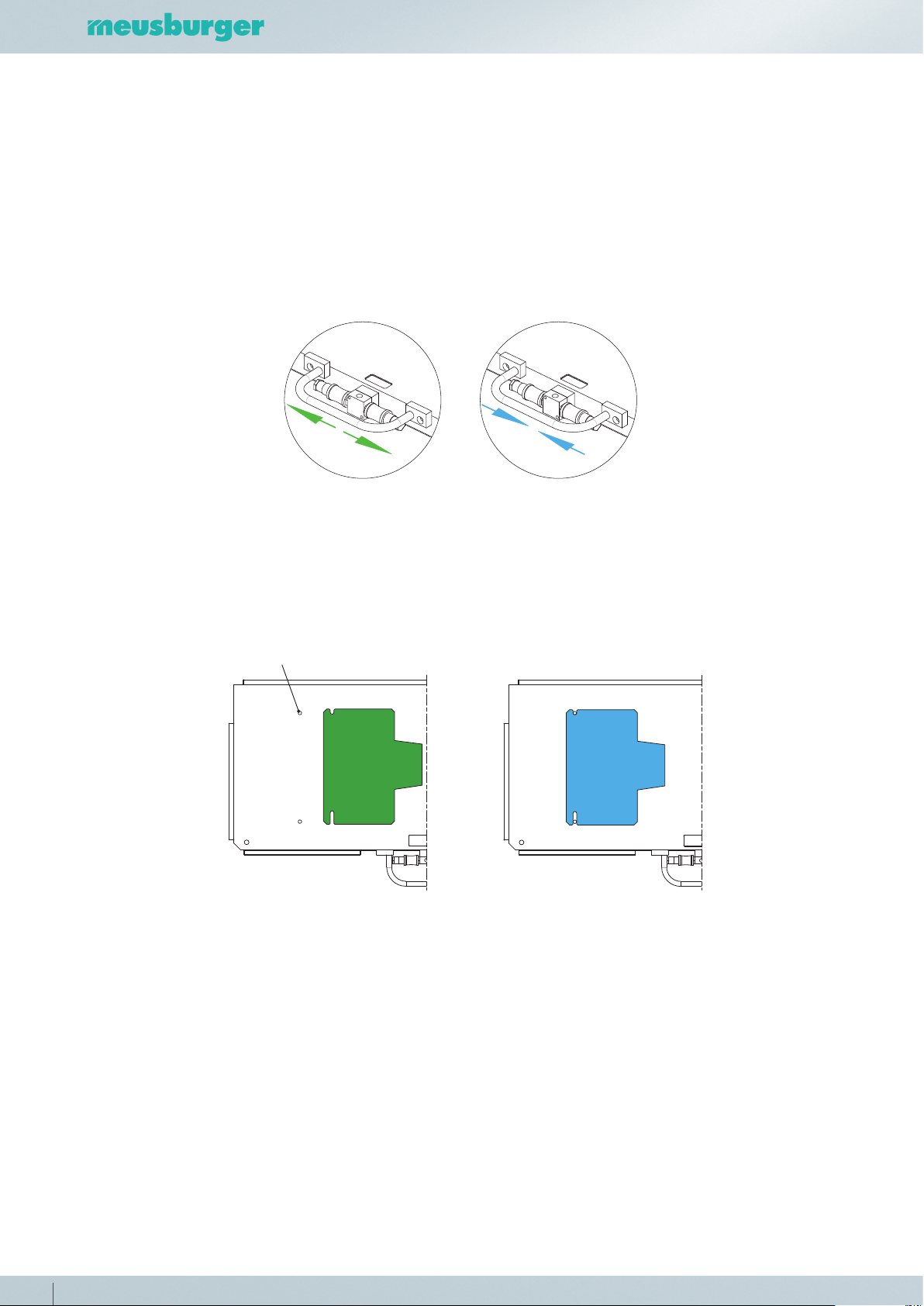
Both halves of the mould can be switched on and o separately using the manu-
al slide valves. In order to avoid any undesirable movements, always activate only
one half of the mould and once the movement has been completed, immediately
switch it o again.
A mould-half can be additionally secured by means of two pins incorporated into
the table‘s surface. Any mould halves that are not in use must always be secured.
6.2. Control and operation
6.2.1. Placing the tool
The tool halves are to be positioned as centrally as possible on the support plates.
Only then is there an optimal air flow and thus the movement of the plates is gua-
ranteed.
6.2.2. Switching the machine on
In order to switch on the machine, first of all, the shut-o valve must be opened. The
manual slide valves can then be used to control each plate individually.
E 1300 Dowel pin
8

6.2.3. Switching the machine o
In order to switch o the machine, both manual slide valves must be closed and
then the main switch turned o. This avoids any unwanted untimely movement of
the pallets caused by turning the shut-o valve.
6.2.4. Emergency shut-down
In an emergency, the shut-o valve must be turned o immediately, so as to cut o
the compressed air supply to the entire system.
7. Maintenance, cleaning, servicing
The correct condition and functioning of all mechanical operating parts must be checked prior to
each use. The schedule for these checks must be set in such a way that any faults that arise can be
detected in good time or any damage immediately rectified. The air hoses must be checked daily
for possible damage. In addition, the table‘s surface and shoulders and the moveable plates must
be oiled regularly, otherwise they will be subject to severe corrosion. The shoulders must be che-
cked regularly to make sure that they are firmly attached.
7.1. Auxiliaries and consumables
Meusburger Multi oil VMM 4/1/400 for the regular oiling of corroding parts.
7.2. Replacement parts and parts subject to wear
Replacement parts may simply be ordered from our sales department. Compressed air hoses
should be renewed after no more than 6 years.
8. Troubleshooting and fault correction
8.1. Fault / malfunction – Cause – Correction
In the event of damage to the compressed air circuit, the circuit must be systematically che-
cked from the pneumatic source right through to the moveable plates.
9. Decommissioning
9.1. Temporary shut-down
In the event of temporary shutdown or storage, the entire assembly table must be oiled,
otherwise it will be subject to severe corrosion. It should be stored in a dry place.
10. Disassembly, removal and disposal
10.1. Recycling
As the assembly table is made of iron and plastics only, it may be disposed of via the conven-
tional system of separated rubbish disposal. Assembly tables that have reached the end of
their service life may be returned to Meusburger Georg GmbH for disposal, free of charge.
9

11. Declaration of conformity
As the manufacturers of this machine, we hereby declare that the machine described below com-
plies with the stated Directives and Standards.
Manufacturer: Meusburger Georg GmbH & Co KG
Kesselstr. 42 | 6960 Wolfurt | Austria
Authorised party in relation to Meusburger Georg GmbH & Co KG
the technical documentation: Kesselstr. 42 | 6960 Wolfurt | Austria
Designation of machine: Air-cushioned assembly table
(Commercial name)
Model, type: H 4062
Serial numbers: H 4062/496/1156. 1 - 999
H 4062/796/1496. 1 - 999
H 4062/996/1846. 1 - 999
Directives: 2006/42 EG Machinery Directive
Normen:
EN ISO 12100 Safety of machinery - General principles for design - Risk assessment
and risk reduction
EN ISO 4414 Pneumatic fluid power – General rules and safety
requirements for systems and their components
EN ISO 13849-1 Safety of machinery – Safety-related parts of control systems
Part 1: General principles for design
EN ISO 13857 Safety of machinery – Safety distances to prevent hazard zones being
reached by upper and lower limbs
ÖNORM EN 842 Safety of machinery – Visual danger signals – General requirements,
design and testing
Wolfurt, 08.04.2021
Place, date Managing Director
10

NOTES
11

Meusburger Georg GmbH & Co KG | Kesselstr. 42 | 6960 Wolfurt | Austria
T +43 5574 6706-0 | verkauf@meusburger.com | www.meusburger.com
Other manuals for H 4062
1
Table of contents
Other Meusburger Indoor Furnishing manuals

Popular Indoor Furnishing manuals by other brands


Viash studios
Viash studios LAX series Wall Mounted Desk Assembly instructions

Bertini
Bertini DA1805-1 instruction manual

BLACK RED WHITE
BLACK RED WHITE STYLIUS B169-REG4D Assembly instructions

fantastic furniture
fantastic furniture Monaco manual

Bretford
Bretford RHOMBII Features

Ameriwood HOME
Ameriwood HOME 3919335COM manual

pottery barn kids
pottery barn kids GRAHAM EXTRA WIDE TOPPER Assembly manual

BetaLife
BetaLife SEVAN 22452 Assembly instructions

Ballard Designs
Ballard Designs WS973 Assembly instructions

comforto
comforto HAWORTH System X-99 manual

Walker Edison
Walker Edison LEEB4C Assembly instructions

Dorel Home Products
Dorel Home Products DA7750G manual