manuals.online logo
Brands
  1. Home
  2. •
  3. Brands
  4. •
  5. Meyer Sound
  6. •
  7. Speakers System
  8. •
  9. Meyer Sound USM-100P User manual

Meyer Sound USM-100P User manual

easily using two L-Track strips
on the top panel that work with
the cabinet’s center of gravity
for easy angle adjustment. A
short bottom strip serves as
an anchor point for fixing tilt
angles. The two SM-P Series
monitors are identical except
for the HF horn configurations.
The SM-1P has a narrow
beamwidth of 45° H x 45° V
to allow close placement with
minimal interaction. The SM-
100P offers a wider 100° H x
40° V pattern for broad
coverage in either wedge or
flown applications. Both horns
were developed in Meyer
Sound’s anechoic chamber,
with prototype designs
measured to 1 degree
resolution at 1/36 octave
intervals. The horns exhibit a
Constant Q characteristic, with
uniform beamwidth across the
horn’s operating range in both
the horizontal and vertical
planes. Amplitude attenuation
outside the beamwidth is rapid
and uniform at all frequencies,
with minimal side lobing.
The dual channel power
amplifier, a proprietary Meyer
Class AB/bridged design with
complementary power MOSFET
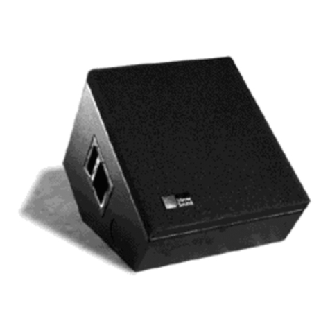
SM-P Series self-powered
stage monitors incorporate a
15-inch low frequency cone
driver, a 3-inch diaphragm
compression driver, phase-
corrected processing
electronics and a dual channel
power amplifier in a rugged
enclosure. Compared to
conventional designs, SM-P
Series monitors are uniquely
capable of producing flat
phase and amplitude response,
full bandwidth reproduction
and a near-perfect impulse
response. Performance
characteristics include a
maximum output of 132
dB peak SPL at 1 m with
exceptionally low distortion.
SM-P Series systems
excel in stage monitoring
applications that require
efficient response down to
30Hz for clean, high level
reproduction of bass and
drums. An additional benefit
of the design engineering and
system packaging of the SM-
P is its improved linearity and
lower susceptibility to feedback.
SM-P monitors can
be deployed as stage wedges
or flown as side-fill or choir
monitors. Rigging is accomplished
FEATURES
output stages, produces 350
Wrms per channel with less
than 0.02% distortion. The
integral driver protection circuit
effectively prevents voice coil
overheating and cone over
excursion, but without the
glaring compression effects
typical of many limiters. The
Intelligent ACTM power supply
provides automatic voltage
selection, EMI filtering, high
voltage transient suppression
and soft start at power-up.
The standard audio input
module includes an XLR-F
input connector, a loop-thru
XLR-M output connector and
24V fan connector (fan optional).
Other input module options are
available. Another optional
module allows integration into
Meyer Sound’s RMS (Remote
Monitoring SystemTM ), a
WindowsTM -based computer
network and software application
for monitoring a full range of
amplifier and driver operating
parameters. Both RMS and
audio input modules may be
installed in the field using only
a Phillips screwdriver.
Self-Powered Reinforcement Loudspeaker
USM-1P/100P
Integrated control
electronics and amplifiers
Bi-amplified
(350 Wrms/channel)
High-power flat
frequency response
Phase-corrected
Constant-Q HF coverage
Narrow (UMS-1P) or wide
(UMS-100P) HF coverage
Modular audio
input options
Intelligent ACTM
System
Compatible with the
Remote Monitoring
SystemTM (RMS)
L-Track rigging system
Superior
engineering
for the art
and science
of sound.
SM-1P
SM-100P
PRELIMINARY
Acoustical1
(each loudspeaker)
Coverage
Crossover
Transducers
Standard Audio
Input Module
Amplifiers
AC Power
Ph sical
Notes
PHYSICAL DIMENSIONS
USM-1P/100P SPECIFICATIONS
Operating Frequency Range2
Free Field
Half-Space3
Phase Response4
Maxi u Peak SPL5
Signal to Noise Ratio
USM-100P
USM-1P
USM-100P
USM-1P
Low Frequency
High Frequency
Type
Connector
I pedance
XLR Wiring
RF Filter
Co on Mode Rejection Ratio
Type
Output Power
THD, IM, TIM
Connector
Auto atic voltage selection
Idle RMS Current
Max Continuous RMS Current (>10 s)
Max Burst RMS Current (<1 s)
Max Peak Current During Burst
Soft Start Turn-on
Di ensions
Weight
Enclosure/Finish
Protective Grill
30 Hz – 20 kHz
44 Hz – 16 kHz ±3 dB; –6 dB at 40 Hz and 20 kHz
40 Hz – 16 kHz ±3 dB; –6 dB at 33 Hz and 20 kHz
±35° 500 Hz – 16 kHz; +90° at 120 Hz
132 dB
>95 dB (A-weighted noise floor to max SPL)
–6 db at 100° H x 40° V; -10 dB at 120° H x 60° V
–6 db at 45° H x 45° V; -10 dB at 60° H x 60° V
900 Hz
1000 Hz
15-inch cone driver
3-inch diaphragm compression driver
Differential balanced input circuit
Female XLR; Male XLR Loop
10 kΩ differential (between pins 2 and 3)
Pin 1: chassis; Pin 2: + signal; Pin 3: – signal
Common Mode: 425 kHz low-pass;
Differential Mode: 142 kHz low-pass
>80 dB (50 Hz – 1 kHz); typically 90 dB
Complementary power MOSFET output stages, class AB/bridged
350 Wrms/channel
<.02 %
PowerCon locking AC connector
88 – 264 VAC continuous; 47 – 63 Hz
115 V: 0.25 Arms 230 V: 0.13 Arms 100 V: 0.3 Arms
115 V: 2.8 Arms 230 V: 1.4 Arms 100 V: 3.2 Arms
115 V: 3.2 Arms 230 V: 1.6 Arms 100 V: 3.7 Arms
115 V: 5.0 Apk 230 V: 2.5 Apk 100 V: 5.8 Apk
Inrush current <15 A @115 V
Height: 16.9” (429mm) ; Width: 16.5” (419mm); Length: 22.4”
(569mm); Depth (w/grill) 15.19” (386mm)
88 lbs (40 kg)
5/8” birch plywood/black textured
Removable perforated steel grill, charcoal grey foam
1. Measurements are taken at 3 m on-axis, 1/3octave, unless otherwise stated.
2. Response depends on loading conditions and room acoustics.
3. Measured at 1.5 m with the SM-1P on a single boundary.
4. Phase variation from pure delay.
5. Measured at 1 m, with pink noise or music.
ALL NITS IN INCHES
Me er Sound Laboratories, Inc.
2832 San Pablo Avenue
Berkeley, CA 94702
tel: 510.486.1166
fax: 510.486.8356
e-mail: techsupport@meyersound.com
http: www.meyersound.com
Meyer Sound Laboratories
has devoted itself to
designing, anufacturing,
and refining co ponents
that deliver superb sonic
reproduction. Every part of
every co ponent is
designed and built to
exacting specifications
and undergoes rigorous,
co prehensive testing
in the laboratories.
Research re ains an
integral, driving force
behind all production.
Meyer strives for sound
quality that is predictable
and neutral over an
extended lifeti e and
across an extended range.
© 2000 Meyer Sound Laboratories, Inc.
All rights reserved
Specifications subject to change without notice
L Approval Pending
USM-100P
USM-1P
USM-1P/100P - 04.089.005.01A
preliminary

This manual suits for next models

1

Other Meyer Sound Speakers System manuals
Meyer Sound MSL-4 User manual

Meyer Sound

Meyer Sound MSL-4 User manual

Meyer Sound Studio Reference Monitor System 833 User manual

Meyer Sound

Meyer Sound Studio Reference Monitor System 833 User manual

Meyer Sound LINA User manual

Meyer Sound

Meyer Sound LINA User manual

Meyer Sound HD-2 User manual

Meyer Sound

Meyer Sound HD-2 User manual

Meyer Sound 500A Series User manual

Meyer Sound

Meyer Sound 500A Series User manual

Meyer Sound UM-1 User manual

Meyer Sound

Meyer Sound UM-1 User manual
Meyer Sound MSL-6 User manual

Meyer Sound

Meyer Sound MSL-6 User manual

Meyer Sound MTS-4A User manual

Meyer Sound

Meyer Sound MTS-4A User manual

Meyer Sound MAPP XT User manual

Meyer Sound

Meyer Sound MAPP XT User manual

Meyer Sound CAL 96 User manual

Meyer Sound

Meyer Sound CAL 96 User manual
Meyer Sound ULTRA XP User manual

Meyer Sound

Meyer Sound ULTRA XP User manual

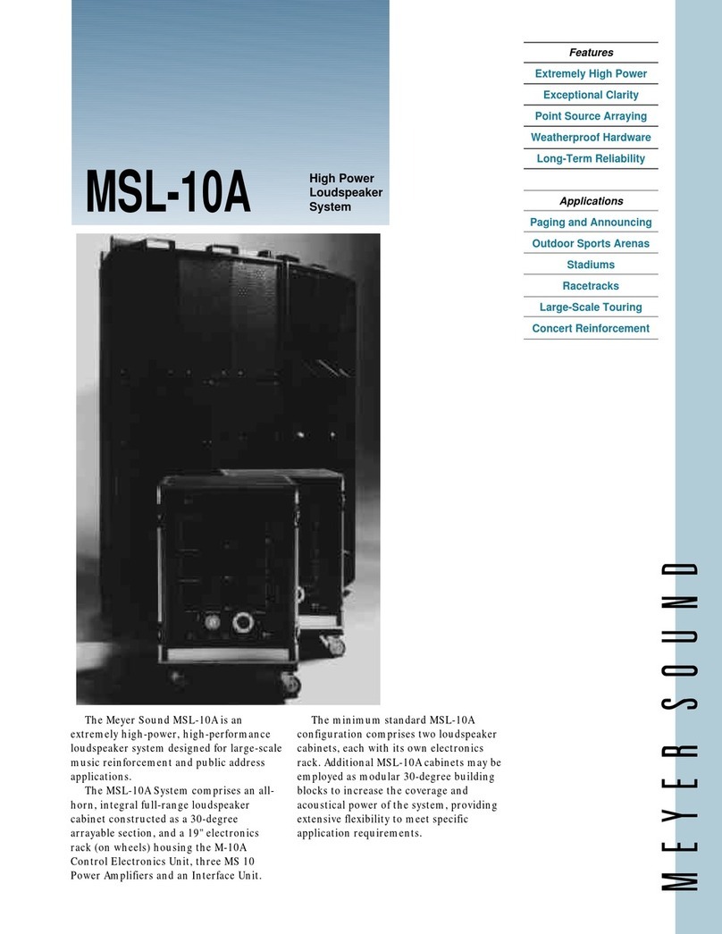
Meyer Sound Loudspeaker MSL-10A User manual

Meyer Sound

Meyer Sound Loudspeaker MSL-10A User manual

Meyer Sound USM-1 User manual

Meyer Sound

Meyer Sound USM-1 User manual

Meyer Sound Acheron User manual

Meyer Sound

Meyer Sound Acheron User manual

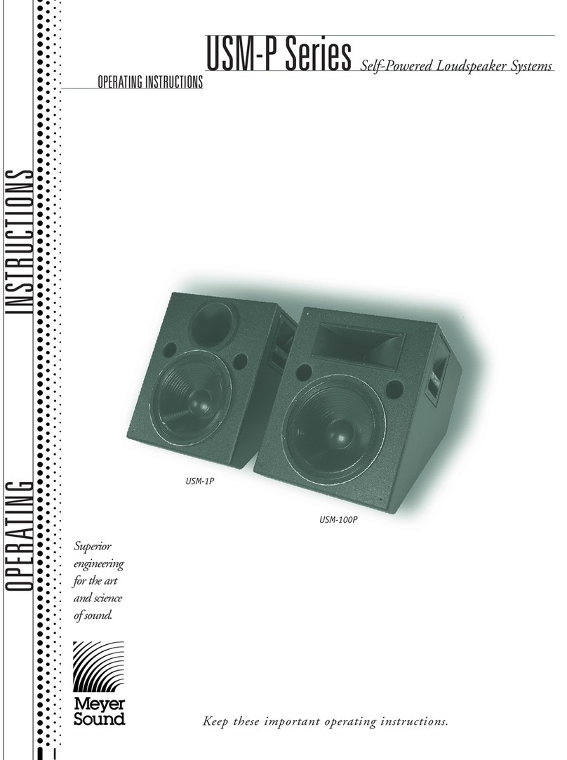
Meyer Sound Self-Powered Loudspeaker Systems USM-P... User manual

Meyer Sound

Meyer Sound Self-Powered Loudspeaker Systems USM-P... User manual

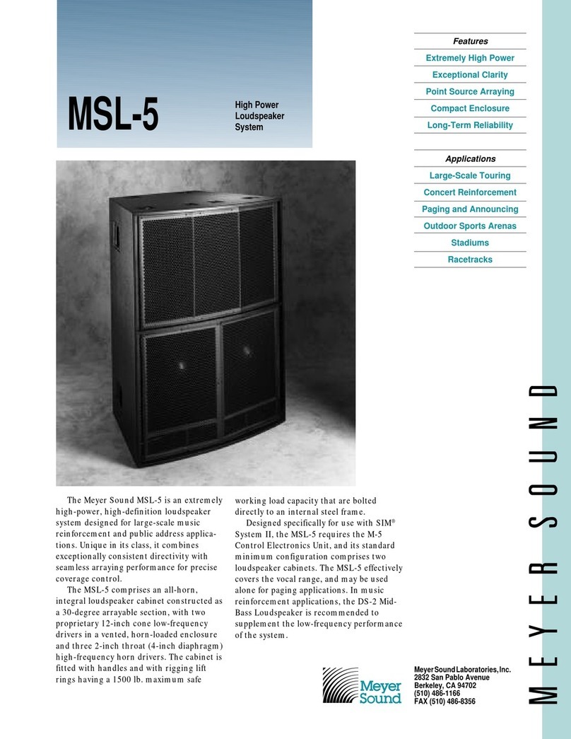
Meyer Sound Loudspeaker MSL-5 User manual

Meyer Sound

Meyer Sound Loudspeaker MSL-5 User manual

Meyer Sound 500 Series User manual

Meyer Sound

Meyer Sound 500 Series User manual
Popular Speakers System manuals by other brands

ENERGY SISTEM SONAR ESG2 user manual

ENERGY SISTEM

ENERGY SISTEM SONAR ESG2 user manual

KV2 Audio KT2.0 user guide

KV2 Audio

KV2 Audio KT2.0 user guide

Samsung HW-M450 Full manual

Samsung

Samsung HW-M450 Full manual

Pioneer XY-122 installation manual

Pioneer

Pioneer XY-122 installation manual

HP StorageWorks 60 Family guide

HP

HP StorageWorks 60 Family guide

Niles Remote Control Anywhere Kit Installation and operation guide

Niles

Niles Remote Control Anywhere Kit Installation and operation guide

Phoenix Gold ZD Series manual

Phoenix Gold

Phoenix Gold ZD Series manual

Yamaha NX-M5 owner's manual

Yamaha

Yamaha NX-M5 owner's manual

IMG STAGE LINE PAK-108 MK2 instruction manual

IMG STAGE LINE

IMG STAGE LINE PAK-108 MK2 instruction manual

TW Audio ELLAL18 Operation manual

TW Audio

TW Audio ELLAL18 Operation manual

Silvercrest 281566 Operating instructions and safety instructions

Silvercrest

Silvercrest 281566 Operating instructions and safety instructions

PULSE+ LSM2141 operation instruction

PULSE+

PULSE+ LSM2141 operation instruction

digi-tech 75WRMS owner's manual

digi-tech

digi-tech 75WRMS owner's manual

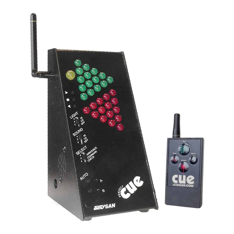
D'San PC-433SYS Perfect Cue user guide
D'San

D'San PC-433SYS Perfect Cue user guide

PowerAcoustik PPF-4 installation manual

PowerAcoustik

PowerAcoustik PPF-4 installation manual

TRU Audio SB-SLIM-44P user manual

TRU Audio

TRU Audio SB-SLIM-44P user manual

Klip Xtreme BluBlade KSB-100 Quick installation guide

Klip Xtreme

Klip Xtreme BluBlade KSB-100 Quick installation guide

ProAudio GR62T user manual

ProAudio

ProAudio GR62T user manual

manuals.online logo
manuals.online logoBrands
  • About & Mission
  • Contact us
  • Privacy Policy
  • Terms and Conditions

Copyright 2025 Manuals.Online. All Rights Reserved.