Toa IP-A1PC238 User guide

RECEIVING DEVICE SETUP MANUAL
IP AUDIO SERIES
Thank you for purchasing TOA's IP Audio Series.
Please carefully follow the instructions in this manual to ensure long, trouble-free use of your equipment.
This manual provides the following explanations:
• Setup and operation of the IP-A1 Device using a web browser.
• SettinguptheDevice’sdetectionandnetworksettingsusingtheIPSettingTool.
For instructions on installation, please refer to the Instruction Manual supplied with the
product.
• Devices covered by this manual:
IP-A1PC238 IP Ceiling Speaker 8W
IP-A1AF IP Audio Interface
IP-A1PC580R IP Ceiling Mount Speaker 8W
IP-A1PC580S IP Square Speaker 8W
• Theexplanationsinthismanualonlyapplytormwareversions2.0.0orlater.
2.0.0

2
TABLE OF CONTENTS
1. INTRODUCTION ................................................................................................ 4
1.1. About This Manual ................................................................................................ 4
1.2. SYSTEM REQUIREMENTS ................................................................................. 4
1.3. SECURITY MEASURES ...................................................................................... 4
2. HOW TO USE THE BROADCAST FUNCTION ............................. 5
2.1. Performing Internal Sound Source Broadcasting ................................................. 5
2.2. Performing Local Broadcasting ............................................................................ 6
2.3. Performing SIP broadcasting ............................................................................... 7
2.4. Performing VMS Broadcasting ............................................................................. 8
2.5. Performing Multicast Broadcasting ...................................................................... 9
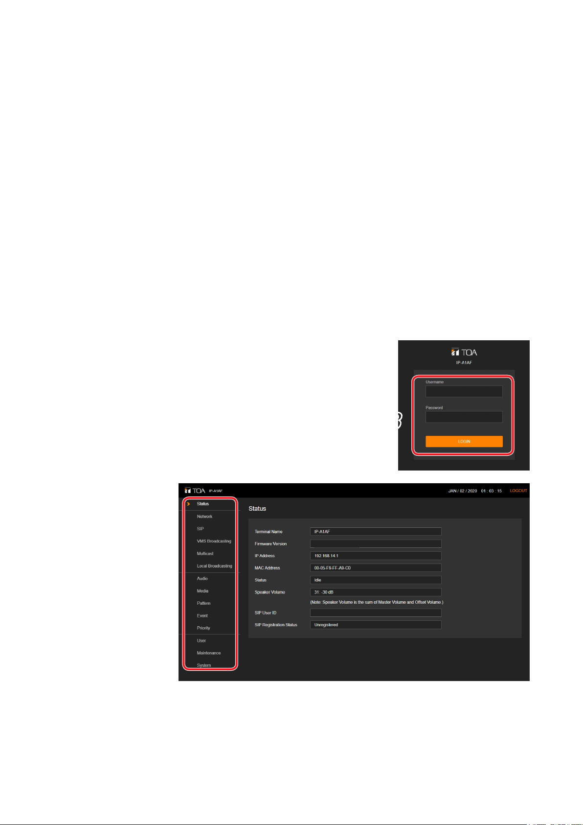
3. CONNECTION WITH BROWSER ......................................................... 10
3.1. Connection Presets ............................................................................................ 10
3.2. Making Connection ............................................................................................ 10
4. CURRENT DATE AND TIME SETTINGS ......................................... 11
4.1. Automatic Date and Time Synchronization with the NTP Server ....................... 11
4.2. SynchronizationwithaConnectedPC’sClock(DateandTime) ....................... 11
4.3. Manual Date and Time Settings ......................................................................... 12
5. OPERATIONS COMMON TO EACH SCREEN ............................. 13
5.1. Screen Layout ..................................................................................................... 13
5.2. Saving Settings or Changed Contents ............................................................... 14
5.3. Restarting the Device ......................................................................................... 15
5.4. Logging Out ........................................................................................................ 15
6. SETTINGS ........................................................................................................... 16
6.1. About the Setting Menu Composition of Each Model ......................................... 16
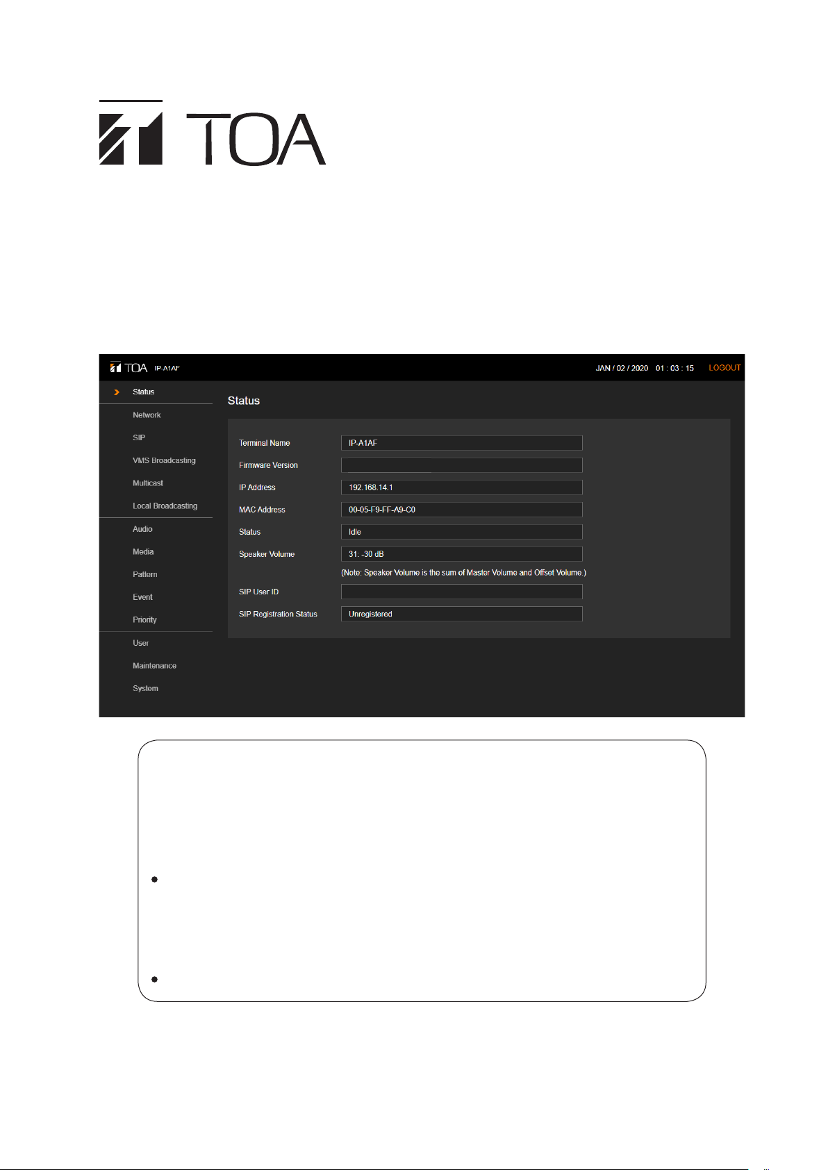
7. STATUS SCREEN DISPLAY ..................................................................... 18
7.1. Status Screen and Status Indicators ................................................................... 19
8. NETWORK SETTINGS SCREEN ......................................................... 20
9. SIP SETTINGS SCREEN ........................................................................... 21
10. VMS BROADCASTING SETTINGS SCREEN ............................ 23
11. MULTICAST SETTINGS SCREEN ..................................................... 24
12. LOCAL BROADCASTING SETTINGS SCREEN ...................... 26
13. AUDIO SETTINGS SCREEN ................................................................. 27
13.1. Conceptual Diagram of the Sound Volume Settings Function ......................... 30
14. MEDIA SETTING SCREEN ................................................................... 32
14.1. Uploading Sound Source Files ......................................................................... 33
14.2. Downloading Sound Source Files .................................................................... 33
14.3. Deleting Sound Source Files ............................................................................ 34

3
15. PATTERN REGISTRATION SCREEN ............................................. 35
15.1. Performing Tests of Pattern Broadcast ............................................................. 39
16. EVENT SETTINGS SCREEN ................................................................ 40
17. PRIORITY SETTINGS SCREEN .......................................................... 44
18. USER SETTINGS SCREEN ................................................................... 47
19. MAINTENANCE SCREEN ....................................................................... 48
19.1. Downloading Setting File ................................................................................. 49
19.2. Uploading Setting File ..................................................................................... 50
19.3. Initialization of Settings .................................................................................... 51
19.4. Factory Default Settings ................................................................................... 52
19.5. Firmware Update .............................................................................................. 53
19.6. Downloading the Log File ................................................................................. 54
20. SYSTEM SETTINGS SCREEN ............................................................ 56
21. USABLE CHARACTERS ......................................................................... 57
21.1. Characters That Can Be Used for Names,
Authentication ID and Passwords ..................................................................... 57
21.2. Characters That Can Be Used for Filenames .................................................. 58
22. IP SETTING TOOL ...................................................................................... 59
22.1. Before Using: .................................................................................................... 59
22.2. Starting the IP Setting Tool .............................................................................. 59
22.3. Setting Method ................................................................................................. 60
22.4. User Authentication .......................................................................................... 62
22.5. Network Settings .............................................................................................. 62
22.6. Uploading Settings Files .................................................................................. 65
22.7. Downloading Settings Files .............................................................................. 66
22.8. Firmware Update .............................................................................................. 67
22.9. Restarting the Device ....................................................................................... 68
23. TROUBLESHOOTING ............................................................................... 69
24. WHAT TO DO WHEN IN TROUBLE ................................................. 74

4
1. INTRODUCTION
1.1. About This Manual
This manual covers the following models:
IP-A1PC238 IP Ceiling Speaker 8W
IP-A1AF IP Audio Interface
IP-A1PC580R IP Ceiling Mount Speaker 8W
IP-A1PC580S IP Square Speaker 8W
Furthermore,theexplanationsinthismanualonlyapplytormwareversions2.0.0orlater.
The display screens used in this manual are mainly related to the IP-A1AF IP Audio Interface. The actual
screens may differ slightly depending on the model.
Additionally, some functions and settings may differ depending on the model. In this manual, if a description
appliesonlytoaspecicmodel,thefollowingwarningwillbedisplayed:
AF Applies only to IP-A1AF.
PC580R/S Applies only to IP-A1PC580R and IP-A1PC580S.
1.2. SYSTEM REQUIREMENTS
Recommended PC operational environments are as follows:
Display Resolution: 1366 x 768 or higher
OS Windows10Pro(64bit)
Windows10Home(64bit)
Windows 11 Pro
Windows 11 Home
Browser Microsoft Edge
Google Chrome
Notes
• Microsoft Edge is the registered trademark of Microsoft Corporation in the United States and other countries.
• Google Chrome is the trademark of Google LLC in the United States and other countries.
1.3. SECURITY MEASURES
• Ensurethatsufcientsecuritymeasuresaretakenonthecustomer’sownresponsibility.
• TOA Corporation takes no responsibility for damage or loss caused by security-related problems, such as
illegal access.
• To help prevent illegal access to the device, be sure to change the user ID and password from those used for
initial setup. For setting methods and other details, please refer to the User Settings Screen on p. 47.
• Takeutmostcareinthemanagementofthedevice’scommunicationspassword.

5
2. HOW TO USE THE BROADCAST FUNCTION
This section describes the Broadcast Settings procedure. To carry out setup, please refer to the following
procedure:
2.1. Performing Internal Sound Source Broadcasting
Toperformbroadcastingfromthelesstoredinthedevice’sInternalsoundsource,pleaserefertothefollowing
setup procedure.
Step 1. Upload sound source les to the device. See p. 32.
• UploadthedesiredsoundsourcelestotheMediaListontheMediaSettingsscreen.
Step 2. Create a broadcast pattern. See p. 35.
• OnthePatternRegistrationscreen,selectasoundsourceleandsettherepetitionmethod,playback
interval, volume, etc. individually for each pattern.
Step 3. Check the audio of the broadcast pattern. See p. 35.
• On the Pattern Registration screen, use the PLAY and STOP buttons to hear the broadcast sounds
from the speaker.
Note
InpatternswhereTimerisselectedastherepeatmethod,thesoundsourcelewillonlybebroadcast
once when the PLAY button is clicked for testing, and not played repeatedly.
Step 4. Set the trigger to play the broadcast pattern. See p. 40.
• On the Event Settings screen, if a created pattern is selected as the control input action, broadcasting
linked to the control input can be performed.
Note
Control inputs or remote API cannot be used for external pattern control when Timer is selected as the
repeat method.
Step 5. Set the broadcast priority. See p. 44.
• Select or change the priority of the pattern created on the Priority Settings screen.
Reboot
• Reboottoreectthesettingchangesmadesofar. Seep. 15.
Step 6. Adjust the broadcast volume.
• On the Pattern Registration screen, adjust the Input Volume to match the output volume of the other
sound sources. See p. 35.
• On the Audio Settings screen, adjust the Master Volume to increase or decrease the overall output
volume from the speaker. See p. 27.

6
2.2. Performing Local Broadcasting
To perform Local Broadcasting from an external sound source device connected to the device, please refer to
the following setup procedure:
Step 1. Enable the Local Broadcasting function. See p. 26.
• Turn ON Local Broadcasting Function on the Local Broadcasting Settings screen.
Step 2. Set a trigger to enable local broadcasting. See p. 40.
• On the Event Settings screen, if Local Broadcasting is selected as the control input action, Local
Broadcasting linked to the control input can be performed.
Step 3. Set the broadcast priority. See p. 44.
• Select or change the Local Broadcasting priority on the Priority Settings screen.
Reboot
• Reboottoreectthesettingchangesmadesofar. Seep. 15.
Step 4. Adjust the broadcast volume. See p. 27.
• On the Audio Settings screen, adjust the Local Broadcast volume to match the output volume of the
other sound sources.
• On the Audio Settings screen, adjust the Master Volume to increase or decrease the overall output
volume from the speaker.
AF

7
2.3. Performing SIP broadcasting
SIP Broadcasting can be enabled by calling the device from a SIP phone or SIP intercom. Please refer to the
following setup procedure:
2.3.1. When performing SIP broadcasting via an SIP server
Step 1. Register with the SIP server. See p. 21.
• Turn ON the SIP Account Active on the SIP Settings screen.
• Set the SIP Server Address, SIP Server Port, User ID, Password, and Authentication ID to connect to
the SIP server.
Step 2. Set the broadcast priority. See p. 44.
• Select or change the SIP Priority on the Priority Settings screen.
Reboot
• Reboottoreectthesettingchangesmadesofar. Seep. 15.
Step 3. Check the registration status on the SIP server.
• ConrmthatthedeviceisregisteredwiththeSIPserverbycheckingtoseeif"Registered"appearsin
the SIP Registration Status on the Status screen or as SIP Account Active on the SIP Settings screen.
See p. 18, p. 21.
Step 4. Adjust the broadcast volume. See p. 27.
• Make a test call to the device from a SIP phone or other SIP device using User ID, then check for audio
output from the speaker.
• On the Audio Settings screen, adjust the volume for each SIP item to match the output volume of the
other sound sources.
• On the Audio Settings screen, adjust the Master Volume to increase or decrease the overall output
volume from the speaker.
2.3.2. P2P SIP Broadcasting
Step 1. Set the broadcast priority. See p. 44.
• Select or change the SIP priority on the Priority Settings screen.
Reboot
• Reboottoreectthesettingchangesmadesofar. Seep. 15.
Step 2. Adjust the broadcast volume. See p. 27.
• Make a test call from a SIP phone or other SIP device to the device by way of its IP Address, then
check for audio output from the speaker.
• On the Audio Settings screen, adjust the SIP volume setting to match the output volume of the other
sound sources.
• On the Audio Settings screen, adjust the Master Volume to increase or decrease the overall output
volume coming from the speaker.

8
2.4. Performing VMS Broadcasting
By registering the device with or connecting it to a network recorder (NVR) or Video Management System
(VMS), VMS broadcasting can be performed using the microphones connected to these clients. For VMS
Broadcast Settings, please refer to the following setup procedure:
Step 1. Enable detection, registration & connection of the device using the ONVIF protocol.
See p. 23.
• Turn ON the VMS Connection on the VMS Broadcasting Settings screen.
• Set the Control Port, RTSP Port, Username and Password to allow detection by or registration with
the NVR or VMS clients.
Step 2. Set the broadcast priority. See p. 44.
• Select or change the VMS Broadcasting priority on the Priority Settings screen.
Reboot
• Reboottoreectthesettingchangesmadesofar. Seep. 15.
Step 3. Register the device with or connect it to NVR or VMS as an ONVIF device.
• Refer to the NVR or VMS instruction manual for more details on detecting, registering or connecting
the ONVIF device.
Step 4. Adjust the broadcast volume. See p. 27.
• Operate the NVR or VMS client and check that the microphone can be used for broadcasting.
• On the Audio Settings screen, adjust the VMS Broadcasting volume to match the output volume of the
other sound sources.
• On the Audio Settings screen, adjust the Master Volume setting to increase or decrease the overall
output volume from the speaker.
Note: ONVIF is the trademark of ONVIF Inc.

9
2.5. Performing Multicast Broadcasting
In order to receive a multicast audio stream for Multicast Broadcasting, please refer to the following setup
procedure:
Step 1. Enable the multicast function. See p. 24.
• Turn ON the Multicast Function on the Multicast Settings screen.
Step 2. Set the port for multicast reception. See p. 24.
• On the Multicast Settings screen, check the multicast channels for which reception will be enabled,
and set the multicast address and receiving port numbers.
Step 3. Set the broadcast priority. See p. 44.
• Select or change the priorities of the multicast channels enabled on the Priority Settings screen.
Reboot
• Reboottoreectthesettingchangesmadesofar. Seep. 15.
Step 4. Adjust the broadcast volume. See p. 27.
• Make sure that audio can be transmitted and broadcast from a device that is capable of multicast
transmission, such as an IP paging gateway.
• On the Audio Settings screen, adjust the volume for each multicast channel to match the output
volume of the other sound sources.
• On the Audio Settings screen, adjust the Master Volume setting to increase or decrease the overall
output volume from the speaker.

10
3. CONNECTION WITH BROWSER
3.1. Connection Presets
The device is factory-preset as follows:
Username: admin
Password: guest
IP address: 192.168.14.1
Subnet mask: 255.255.255.0
Default gateway: 0.0.0.0
Before connecting a PC to the device and changing its setting, it will be necessary to set the PC's network settings
so that it can operate on the same network as the device. Take care that no IP addresses are duplicated in the
same network. For example, if the device's IP address is 192.168.14.1, set the PC's IP address to 192.168.14.10
or the like.
3.2. Making Connection
Notes
• Avoid simultaneously connecting to the device from multiple PCs.
• Avoid simultaneously connecting to the device from a single PC using multiple browsers.
Step 1. Connect both the device and the PC to be used for setup to the network.
Step 2. StartthePC'sbrowserandenterthedevice'sIPaddressintheaddresseld.
Example: 192.168.14.1
The Login screen will be displayed.
Tip
Default IP address: 192.168.14.1
Step 3. Enter both the username and the password, and click on the LOGIN
button.
The Status screen will be displayed.
Click on the individual function names arranged on the left side
of the browser screen to switch screens and perform the required
settings for each selected screen.
3
2.0.0

11
4. CURRENT DATE AND TIME SETTINGS
Before beginning to use the device, be sure that the current date and time are correctly set. This initial setting
isrequiredinordertoaccuratelysetandoperatethedevice’sTimerfunctionorconrmitslogs.Firstgotothe
Systemsettingsscreentoperformthesesettings(p. 56).
4.1. Automatic Date and Time Synchronization with the NTP Server
Step 1. Switch ON NTP and designate the NTP
server to be used to synchronize the date
and time.
Up to two different NTP servers can be
set. Enter the IP address or domain for
NTPServers1and2.NTPServer1takesprecedenceandwillbesynchronizedrst.
Step 2. Select the Time Zone.
Select the Time Zone of the location where
the device is installed.
Step 3. Click on the SAVE button.
Any changes to the settings are saved
while the date and time are simultaneously
synchronized with the NTP server.
If synchronization is successful, the
indication “Synchronized” is displayed.
Tip
This device can be synchronized with an NTP server when NTP is switched ON and…
• The SAVE button is clicked.
• The device is restarted.
• Thedevice’sclockissynchronizedeverydayat00:01.
However, no synchronization is possible if the receiving device is currently broadcasting.
4.2. Synchronization with a Connected PC’s Clock (Date and Time)
Step 1. Switch ON Sync with PC.
Settings can be changed when the NTP function is switched OFF.
Step 2. Select the Time Zone.
Select the Time Zone of the location where the device is installed.
Step 3. Click on the SAVE button.
Any changes to the settings are saved while the date and time are simultaneously synchronized with
the PC displaying the setting screen. Note that synchronization is only performed once, and not on a
regular basis.
Synchronized

12
4.3. Manual Date and Time Settings
Step 1. Enter the current date and time in the Manual Setting box.
When both NTP and Sync with PC are set
to OFF, the date and time can be entered
manually.
Step 2. Select the Time Zone.
Select the Time Zone of the location where the device is installed.
Step 3. Click on the SAVE button.
The entered date and time are saved.

13
5. OPERATIONS COMMON TO EACH SCREEN
5.1. Screen Layout
Name Description
(1) Settings Menu Clicking on the Settings menu automatically switches the screen to the Setting
Items window. If a setting item is changed, click on the SAVE button to save the
changed contents before switching from the Setting Items window.
(2) Setting Items Window Displays the setting items for each Settings menu. If a setting item is changed,
click on the SAVE button to save the changed contents before switching from
the Setting Items window.
(3) SAVE Button Saves the changed setting contents.
(4) Current Time Display Displaysthebuilt-inclock’scurrenttime.
(5) LOGOUT Button Clickthisbuttontologoutonlyafterconrmingcompletionofsettingcontents
entry or changes. The Logout screen is displayed after logging out.
2
3
4 5
1

14
5.2. Saving Settings or Changed Contents
If any setting items are changed, these changes need to be saved. Note that there may be cases where settings
or changes are applied immediately or only after restarting the device.
5.2.1. Cases in which settings or changes are immediately applied
Step 1. Click on the SAVE button.
The following message appears, notifying the user
that the setting or change has been immediately
applied:
< Pattern Registration Screen > < Audio Settings Screen >
Step 2. Click on the OK button.
5.2.2. Cases in which settings or changes are only applied after device restart
Step 1. Click on the SAVE button.
The message at right appears, notifying the user
that the changed contents will only be applied
after device restart.
Step 2. Click on the OK button.
Step 3. Move to the Maintenance screen and click on
REBOOT.
Note
Attempting to switch screens without clicking on the SAVE button after
changesaremadetothesettingsorcontentsofeachscreen(Status
screen,MediaSettingsscreenandMaintenancescreenexcepted)will
cause the screen at right to appear:
• Ifsavingchangesmadetothesettingcontentsofascreen,rstclick
on the NO button, then the SAVE button, before switching screens.
• If not saving changes made to the setting contents, click on the YES
button. The display will switch to another screen without saving the
contents.

15
5.3. Restarting the Device
Theprocedureforrestarting(orrebooting)thedeviceisasfollows:
Step 1. Move to the Maintenance screen.
Step 2. Click on the REBOOT button.
Aconrmationdialogboxisdisplayed.
Step 3. Click on the YES button.
The network connection with the device is disconnected, causing the device to automatically restart.
5.4. Logging Out
LOGOUT button
Toterminatethenetworkconnectionaftercompletingconrmationorchangestothedevice'ssettings,clickon
the LOGOUT button.
When logged out, the Login screen will be displayed.
1

16
6. SETTINGS
6.1. About the Setting Menu Composition of Each Model
The setting menu to be displayed on the left side of the screen differs depending on the model.
IP-A1PC238 IP-A1AF IP-A1PC580R, IP-A1PC580S
1
2
3
4
5
7
8
9
10
11
12
13
14
1
2
3
4
5
6
7
8
9
10
11
12
13
14
1
2
3
4
5
7
8
9
10
11
12
13
14

17
Setting Name Setting Item
Application
of setting
changes
Page
(1) Status screen Conrmation of current rmware version, network
settings, volume setting —p. 18
(2) Network Settings
screen
Network settings such as the IP address After restart p. 20
(3) SIP Settings screen Settings of SIP connection enable/disable, SIP
server address, authentication information, and
audio codec
After restart
p. 21
(4) VMS Broadcasting
Settings screen
Settings of VMS connection enable/disable and
authentication information, connection port settings After restart p. 23
(5) Multicast Settings
screen
Settings of multicast reception enable/disable,
multicast address and port, and control output
during multicast broadcast
After restart
p. 24
(6) Local Broadcasting
Settings screen
AF
Settings of local broadcasting function enable/
disable.
Tip
When the local broadcasting function is enabled,
theaudio(SIPcallandVMSmonitoringaudio)from
this device to network is muted.
After restart
p. 26
(7) Audio Settings
screen
Settings of speaker volume, input volume for
individual broadcast classications, and the
sensitivity of LINE/MIC input for SIP and VMS
broadcasting
Immediately
p. 27
(8) Media Settings
screen
Uploading/downloading or deletion of sound source
les such as messages to or from the internal
memory
—
p. 32
(9) Pattern Registration
screen
Registration of sound source playback to be
associated with events as patterns
Immediately
p. 35
(10) Event Settings
screen
Settings of operations to be synchronized with the
control input and control output After restart p. 40
(11) Priority Settings
screen
Settings of priority order for each broadcast mode;
SIP broadcast, VMS broadcast, multicast broadcast
and internal sound source broadcast
After restart
p. 44
(12) User Settings screen Changing username and password
Immediately
p. 47
(13) Maintenance screen Download and upload the conguration le,
initialization, rmware update, hardware reboot,
and downloading action logs
—
p. 48
(14) System Settings
screen
Date and time settings, NTP server settings, Time
zone settings
Immediately
p. 56

18
7. STATUS SCREEN DISPLAY
This screen displays the device's state.
Since this page only displays the current settings, the contents cannot be changed on this page.
Item Contents
(1) Terminal Name DisplaysthedevicenamesetontheNetworksettingsscreen(p. 20).
(2) Firmware Version Displays the device's current rmware version. (See "Firmware Update" on p.
53.)
(3) IP Address Displaysthedevice'sIPaddresssetontheNetworksettingsscreen(p. 20).
(4) MAC Address Displays the device's MAC address.
(5) Status Displays the device's operating status.
Idle: Standby state
SIP Calling: Call to a SIP device in progress
SIP: SIP broadcasting in progress
VMS Broadcasting: VMS broadcasting in progress
Multicast 1 – 20: Multicast broadcasting in progress.
(Displaysthecurrentlyreceivedchannelnumbers.)
Pattern1–20(soundsourcelename):
Internal sound source broadcasting in progress.
(Displays the pattern number and the sound source
lenamecurrentlybeingexecuted.)
Local Broadcasting: Local broadcasting in progress.
SystemMute: Systemcurrentlybeingmuted(byMutecontrolenabled
bytransmitter).
(6) Speaker Volume Displays the current speaker output volume, which is the sum of the Master
Volume and Offset Volume. The Master Volume can be set on the Audio
Settings screen.
(7) SIP User ID Displays the device's name when registering the device on the SIP server.
(See"SIPSETTINGSSCREEN"onp.21.)
(8) SIP Registration
Status
Displaysthedevice'suserIDregisteredonaSIPserver.(See"SIPSETTINGS
SCREEN"onp.21.)
Registered: Registration successful.
Registration Failed: Registration failed.
Registering: Registration in progress.
Unregistered: Registration invalid.
2.0.0
1
2
3
4
5
6
7
8

19
7.1. Status Screen and Status Indicators
DisplayofStatusitemsontheStatusscreenandstatusindicators(StatusLED)havethefollowingrelationship:
Device operation Status display on the Status
screen
Statusindicator(StatusLED)
IP-A1PC238
(Orange)
IP-A1AF, IP-A1PC580R/S
(Green,Blue,Yellow,Red)
System startup
—
Flashing twice
0.5 - 0.5 - 1sec
Flashing green
0.5 - 0.5 - 1sec
Broadcast standby Idle Continuously lit Continuously lit green
Broadcasting SIP / SIP Calling
VMS Broadcasting
Multicast 1 ~ 20
Pattern 1 ~ 20
Local Broadcasting AF
Continuously lit Continuously lit blue
System mute*
System Mute
Flashing quickly
0.5 - 0.5sec
Flashing red
0.5 - 0.5sec
Initialization or
rmwareupdating —
Flashing slowly
2 - 1sec
Continuously lit yellow
* System mute is a state in which this device is muted by the control from the transmitting device.

20
8. NETWORK SETTINGS SCREEN
The device's network-related settings are performed on this screen.
Item Contents
(1) Terminal Name*1, *2Set the device's terminal name.
Initialsetting:(ProductNumber)
(2) IP Address*2Set the device's IP address.
Only private addresses can be entered.
Initial set ting: 192.168.14.1
(3) Subnet Mask*2Set the device's subnet mask.
Initial setting: 255.255.255.0
(4) Default Gateway*2Set the device's default gateway.
Initial setting: 0.0.0.0
(5) DNS Server Set the primary and secondary DNS server addresses.
Initialsetting:0.0.0.0(Invalid)
(6) HTTP Port Set the HTTP server support numbers. Normally, this port is used as found in
the initial settings.
Setting Range: 80 or 10000 – 40000
Initial setting: 80
(7) SAVE button Clicktosavethesettingsandchanges.(Seep. 14.)
*1For more information on the characters or number of characters that can be set, please refer to "USABLE
CHARACTERS"onp.57.
*2 This item causes the original setting values to be maintained without changing when the settings le is
uploaded.
1
2
3
4
5
6
7
Other manuals for IP-A1PC238
1
This manual suits for next models
3
Table of contents
Other Toa Speakers manuals