manuals.online logo
Brands
  1. Home
  2. •
  3. Brands
  4. •
  5. Meyer Sound
  6. •
  7. Speakers
  8. •
  9. Meyer Sound UltraMonitor UM-1C User manual

Meyer Sound UltraMonitor UM-1C User manual

Operating Instructions
Meyer Sound Laboratories, Inc.
2832 San Pablo Avenue
Berkeley, CA 94702
UM-1C
UltraMonitorTM
The UM-1C is designed to be operated as a system
with the Meyer Sound M-1A Control Electronics
Unit (one M-1A per channel). The M-1A comprises
electronic crossover, Meyer Sound exclusive
SpeakerSenseTM driver protection circuitry, and
amplitude and phase response alignment circuitry
optimized for the loudspeaker.
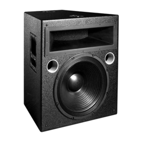
The Meyer Sound UM-1C UltraMonitorTM is a
compact, high-power biamplified loudspeaker
designed specifically for stage monitor applications.
It consists of a proprietary 12-inch low-frequency
cone driver with a symmetrical 60-degree high-
frequency horn and driver in a vented enclosure.
Operating Instructions
Meyer Sound Laboratories, Inc.
2832 San Pablo Avenue
Berkeley, CA 94702
UM-1C
UltraMonitorTM
■Standing in front of the loudspeaker, position the
analyzer microphone directly between the horn and
the 12-inch driver, at right angles to the cabinet face,
and about 20 inches in front of the UM-1C.
■If polarity of the horn driver is reversed, a trough will
appear in the response curve, centered near 1600 Hz.
If in doubt, reverse the polarity of the Hi amplifier output
while you watch the analyzer display.
2. Multiple cabinets.
Each cabinet should first be tested as above.
■Connect one loudspeaker and advance the pink noise
to a convenient measuring level. Position the measuring
microphone between two adjacent loudspeakers, and
about six feet distant. Note the frequency response and
overall level.
■Leaving the first loudspeaker connected, connect the
adjacent one and observe the analyzer display.The
entire curve should jump up in level, indicating correct
addition between the loudspeakers. If the loudspeakers
are adjacent, a polarity reversal between them will show
up as severe broadband cancellation. As the loudspeak-
ers are moved apart, the cancellation will become less
apparent at high frequencies. For this reason, polarity
testing should be done with cabinets adjacent.
All Meyer Sound loudspeakers are thoroughly tested
in all stages of manufacture and correct polarity of indi-
vidual cabinets is assured. However, accidental polarity
reversal is possible when there are multiple amplifier
connections. A cabinet which is out of polarity with the
rest of the system will cause severe cancellation, result-
ing in a noticeable decrease in SPL and possible compo-
nent damage.
Because of the extensive signal processing circuitry of
the M-1A Control Electronics Unit, the “phase-popper”
type of speaker phase checkers cannot reliably be used
to test for correct polarity of the low and high drivers of
the UM-1C. However, because the UM-1C is phase
corrected through crossover, any of the portable spectrum
analyzers can be used, with a pink noise source, to test
for driver polarity as follows:
1. Single cabinets.
First, verify polarity of the woofer by connecting a 9 volt
battery at the end of the loudspeaker cable.
Cannon connector Battery
Pin 1 + terminal
Pin 2 – terminal
■The woofer cone should move outward toward the
listener. Connect the speaker cable to the amplifier.
■Input the pink noise source to the M-1A and advance
the M-1A input Level
control to a convenient measuring level.
Verifying System Polarity
Note. If you are using standard Meyer Sound loudspeaker
cables and adapters, simply connect the female end of
the loudspeaker cable to the UM-1C, the male end of the
cable to the Meyer Sound pigtail adapter, and the banana
connectors of the adapter to your amplifier outputs. In
making connections between the UM-1C and the amplifier,
be sure to connect the 12-inch driver to the Lo channel,
and the horn driver to the Hi channel.
The adapter banana plugs are color-coded as follows:
Red — Low frequency driver
Black — High frequency driver
For connections between the M-1A and the power ampli-
fier, refer to the M-1A Operating Instructions.
The UM-1C is a biamplified system and must be used
with the M-1A Control Electronics Unit. The M-1A
functions as an active crossover, dividing the input signal
into high and low frequency components.
The connection terminals of the low and high frequency
drivers appear on a single Cannon P-type 4-pin connec-
tor located on the rear of the UM-1C cabinet. The pin
assignments for this connector are:
Pin 1 — 12-inch driver, hot
Pin 2 — 12-inch driver, common
Pin 3 — horn driver, common
Pin 4 — horn driver, hot
(When the cabinet is fitted with a Cannon EP-5
connector, Pin 5 is unconnected.)
The minimum wire size for connections between the
UM-1C and the power amplifier should be 14 gauge.
Connections
Amplifier Requirements The UM-1C requires a professional quality two-channel
power amplifier rated at 200-300 watts per channel
continuous into 8 ohms. (If two UM-1Cs are to be oper-
ated in parallel from the amplifier, it should be capable
of driving 4 ohms.) Use of amplifiers of lower power will
not allow the full power and headroomofthe UM-1C
system to be realized (though this may be acceptable in
applications where high pressure levels are not required).
Conversely, use of amplifiers rated at significantly more
than 300 watts per channel may endanger the loud-
speaker, and is not recommended.
For further information on power amplifiers, please refer
to Choosing a Power Amplifier, a Meyer Sound Techni-
cal Note available from your dealer.
Operating Instructions
Meyer Sound Laboratories, Inc.
2832 San Pablo Avenue
Berkeley, CA 94702
UM-1C
UltraMonitorTM
When the UM-1C is placed on the floor in its normal posi-
tion (horn facing up towards the performer), there will be
a boost in the low frequency response of the loudspeaker.
This is caused by the loudspeaker coupling with the floor,
and may be corrected at the M-1A Control Electronics
Unit by switching in the Lo Cut filter on the Preset Panel.
Please refer to the M-1A Operating Instructions for a
complete description of its controls.
Placement of the
UM-1C UltraMonitor
Rigging The UM-1C loudspeaker has four steel rigging brackets
internally mounted as an integral part of the cabinet
design and the cabinet is supplied with either aircraft pan
fittings (ring or stud) or 3⁄8"–16 nut plates according to
user preference. A flat plate is supplied when no rigging
hardware is specified. All three plate types are held in
place by six Phillips-head machine screws and can be
interchanged at any time. The handles on the UM-1C
cabinet are provided solely for moving and carrying the
loudspeaker and are not to be used for rigging purposes.
The rigging hardware is so designed that a single point
can support the normal load for the cabinet. In the
case of the UM-1C, the recommended maximum load is
420 lbs (190 kg). Any of the individual rigging points is
capable of supporting this load with an adequate safety
margin. However, Meyer Sound strongly recommends
that safety lines be run to the other points. If the struc-
tural integrity of any cabinet has been compromised by
damage or negligence, then the safety of the rigging
cannot be assured. All rigging should be done by
competent professionals.
The UM-1C UltraMonitor is designed to be used as a
stage monitor. However, its compact size and perfor-
mance capabilities make it a practical side- or front-fill
PA speaker. The 60-degree symmetrical coverage
pattern of the high frequency horn is most effective in
situations where narrow coverage angles are preferred.
High Frequency
Network The UM-1C loudspeaker contains, mounted in the enclo-
sure, a DC protection and response correction network
for the high-frequency horn driver. The network is
mounted directly behind the MS-12 low-frequency cone
driver on the inside rear face of the cabinet, and is wired
in series with the horn driver.
The circuit board is fitted with five terminals, two of which
(labeled AMP- and AMP+) are wired to the Cannon EP-4
connector pins 3 and 4. The other terminals (labeled
FLAT and 16KPK), provide two options for tailoring the
system’s response. With the high driver common (green)
wire connected to the FLAT terminal, the UM-1C high-
frequency response is nominally flat to 20 kHz. When the
common wire is connected to the 16KPK terminal, the
UM-1C exhibits a peaked response in the 16 kHz region.
The UM -1C is shipped with the high driver common
connected for flat response. Should you desire more
high-frequency energy, simply remove the six bolts
holding the MS-12 in place, pull the MS-12 up and out of
the cabinet, and move the green wire from the FLAT
terminal to the 16KPK terminal. Be careful not to disturb
the other wires to the network board or Cannon connec-
tor. When replacing the MS-12, be certain to tighten the
six bolts evenly.
AMP+
WHT
AMP -
GRN
TESTED:_________
DATE:___________
DRVR+
WHT
FLAT
DRVR-
GRN
©1992 Meyer Sound Y-1PD PCB
Assy. # 24.052.103._________Rev_________
16KPK
UM-1C High-Frequency Network Circuit Board
Operating Instructions
Meyer Sound Laboratories, Inc.
2832 San Pablo Avenue
Berkeley, CA 94702
UM-1C
UltraMonitorTM
Specifications Acoustical - UM-1C/M1A System
Frequency Response170 Hz to 18 kHz ±4dB
-6 dB at 55 Hz and 20 kHz
Maximum SPL2 with amplifier rated at: 250W/8 ohms/ch 60W/8 ohms/ch
Continuous 125 dB 120 dB
Peak 132 dB 126 dB
HF Coverage Pattern 60 degrees symmetrical
UM-1C Loudspeaker
Driver Complement
Low Frequency Driver MS-12
High Frequency Driver MS-1401B
High Frequency Horn 60-degree constant-directivity
1600 Hz to15 kHz
HF Network Y-1PD
Function DC blocking and damped
band-elimination filter
Enclosure 0.8 cu. ft. vented, multi-ply
Finnish birch plywood
Finish Black textured
Physical Dimensions 14" W x 14" H x 22 1⁄2" D
Weight 61 lbs (27.7 kg)
Protective Grill perforated steel screen, vinyl damped,
charcoal-grey foam covering
Connector Cannon EP-4 (male), EP-5 (male, Europe only)
Rigging (optional) Aircraft pan fittings, or 3⁄8"-16 or M10 x 1.5 nut plate
Meyer Sound Part Number 05051044.03 Revision A, November 1992
© Meyer Sound, 1985 - 1992. All rights reserved. This document may not be reproduced without permission.
Note 1:
Measured 1⁄2meter
from center of cabinet
face, half-space condi-
tions, pink noise input,
network set to 16KPK,
smoothed to one-third
octave. Low frequency
response dependent on
load conditions.
Note 2:
Loudspeaker driven
with pink noise.

Other Meyer Sound Speakers manuals

Meyer Sound M2D User manual

Meyer Sound

Meyer Sound M2D User manual

Meyer Sound M SERIES User manual

Meyer Sound

Meyer Sound M SERIES User manual

Meyer Sound Mina User manual

Meyer Sound

Meyer Sound Mina User manual

Meyer Sound MILO User manual

Meyer Sound

Meyer Sound MILO User manual

Meyer Sound MILO 120 User manual

Meyer Sound

Meyer Sound MILO 120 User manual

Meyer Sound UPJunior User manual

Meyer Sound

Meyer Sound UPJunior User manual

Meyer Sound CQTM Series User manual

Meyer Sound

Meyer Sound CQTM Series User manual

Meyer Sound M3D-SUB User manual

Meyer Sound

Meyer Sound M3D-SUB User manual

Meyer Sound LEO Series User manual

Meyer Sound

Meyer Sound LEO Series User manual

Meyer Sound Compact VariO UPJ-1P User manual

Meyer Sound

Meyer Sound Compact VariO UPJ-1P User manual

Meyer Sound PARABOLIC SOUND BEAM SB-1 Instruction Manual

Meyer Sound

Meyer Sound PARABOLIC SOUND BEAM SB-1 Instruction Manual

Meyer Sound UPL-2 User manual

Meyer Sound

Meyer Sound UPL-2 User manual

Meyer Sound UPL-1 User manual

Meyer Sound

Meyer Sound UPL-1 User manual

Meyer Sound High-Power Loudspeaker MSL-2A User manual

Meyer Sound

Meyer Sound High-Power Loudspeaker MSL-2A User manual

Meyer Sound Self-Powered Loudspeaker HM-1 User manual

Meyer Sound

Meyer Sound Self-Powered Loudspeaker HM-1 User manual

Meyer Sound UP-4XP User manual

Meyer Sound

Meyer Sound UP-4XP User manual

Meyer Sound UPM-1P User manual

Meyer Sound

Meyer Sound UPM-1P User manual

Meyer Sound Control Electronics Unit MPS-3 User manual

Meyer Sound

Meyer Sound Control Electronics Unit MPS-3 User manual

Meyer Sound DS-2 User manual

Meyer Sound

Meyer Sound DS-2 User manual

Meyer Sound UltraSeries UPA-2C User manual

Meyer Sound

Meyer Sound UltraSeries UPA-2C User manual

Meyer Sound USM-1P User manual

Meyer Sound

Meyer Sound USM-1P User manual

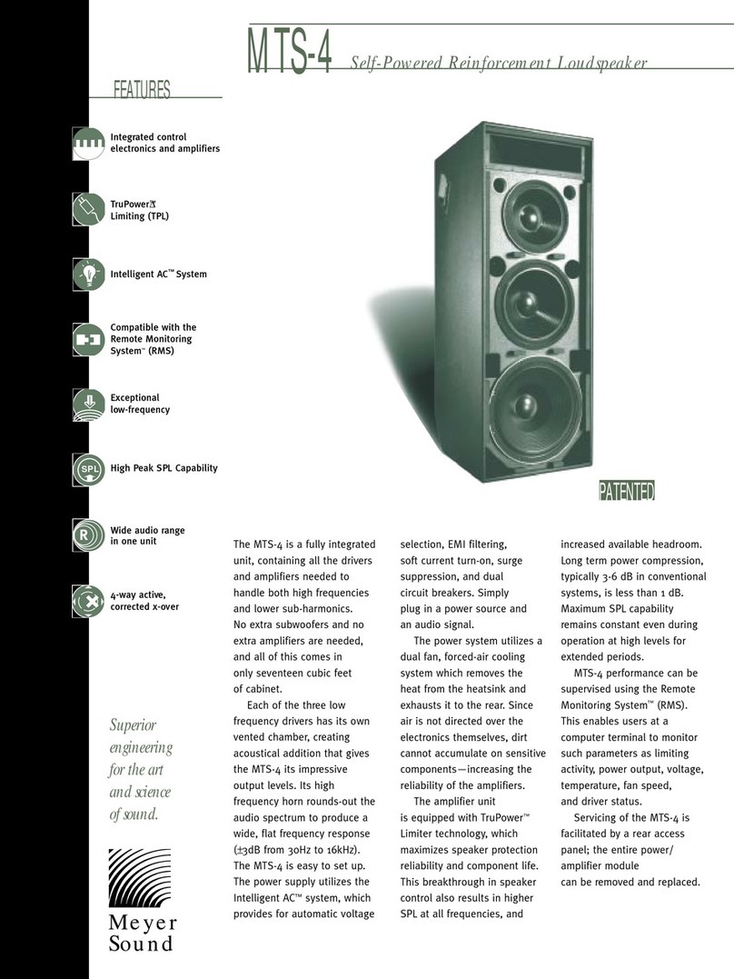
Meyer Sound Self-Powered Reinforcement Loudspeaker MTS-4 User manual

Meyer Sound

Meyer Sound Self-Powered Reinforcement Loudspeaker MTS-4 User manual

Meyer Sound M SERIES User manual

Meyer Sound

Meyer Sound M SERIES User manual

Meyer Sound MM-4XP User manual

Meyer Sound

Meyer Sound MM-4XP User manual

Popular Speakers manuals by other brands

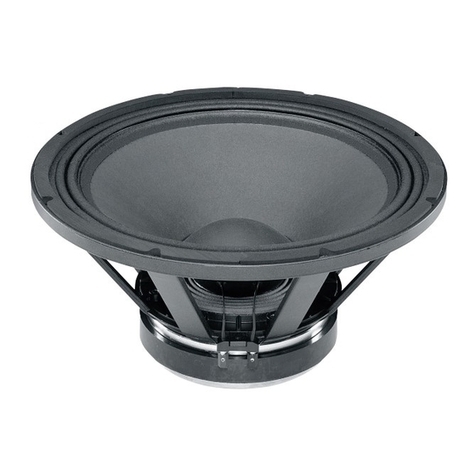
B&C Speakers Woofer 18 PZB 46 Specifications

B&C Speakers

B&C Speakers Woofer 18 PZB 46 Specifications

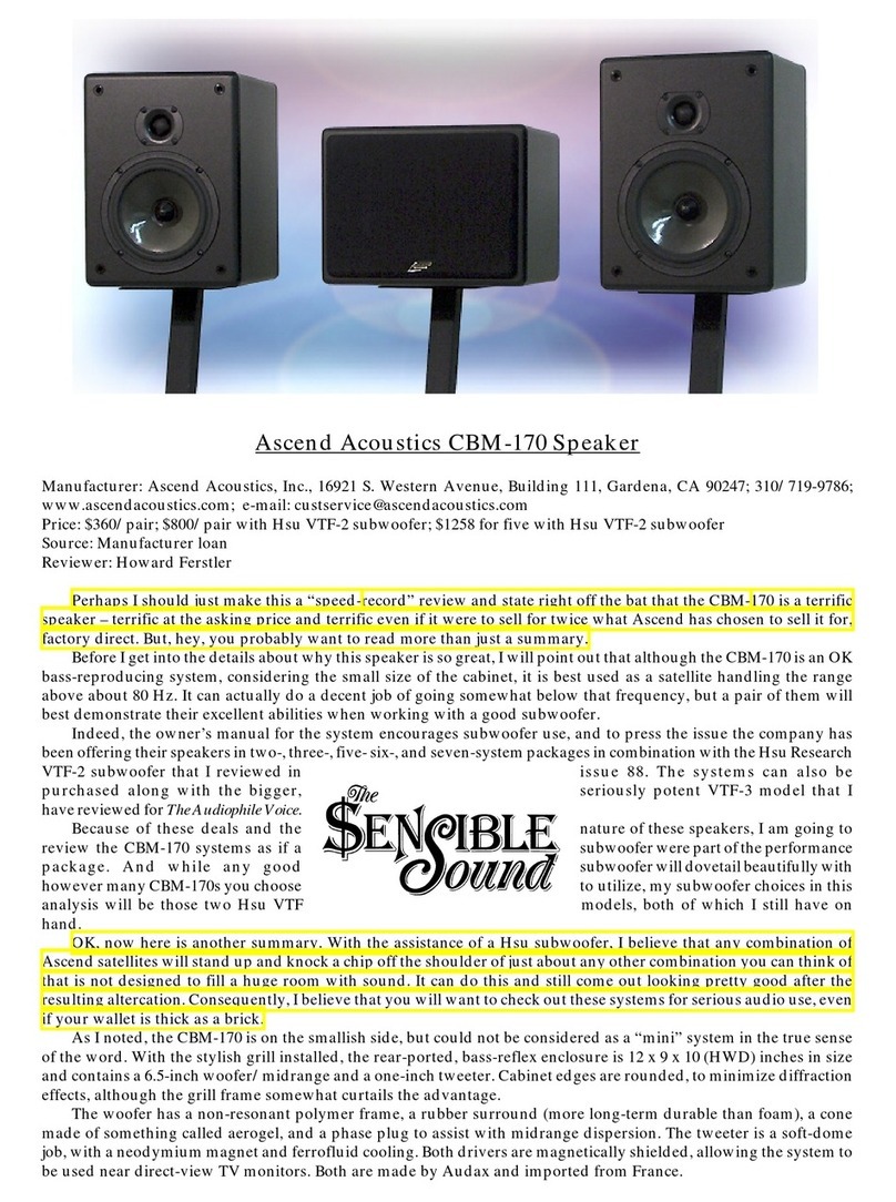
Ascend Acoustics CBM-170 quick guide

Ascend Acoustics

Ascend Acoustics CBM-170 quick guide

Sanus Systems HTB7 instruction manual

Sanus Systems

Sanus Systems HTB7 instruction manual

Weiking BT24S manual

Weiking

Weiking BT24S manual

DAPAudio K-115A Product guide

DAPAudio

DAPAudio K-115A Product guide

Acoustic Energy Aelite Two user manual

Acoustic Energy

Acoustic Energy Aelite Two user manual

Philips BTM3360/96 user manual

Philips

Philips BTM3360/96 user manual

JBL 4428 Technical manual

JBL

JBL 4428 Technical manual

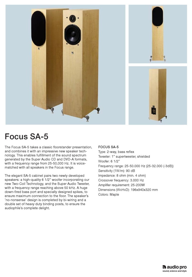
Audio Pro Focus SA-5 Specifications

Audio Pro

Audio Pro Focus SA-5 Specifications

EDIFIER TickTock Bluetooth-MF240BT user manual

EDIFIER

EDIFIER TickTock Bluetooth-MF240BT user manual

Tivoli Audio NetWorks Speaker owner's manual

Tivoli Audio

Tivoli Audio NetWorks Speaker owner's manual

Pioneer XY-81-W user manual

Pioneer

Pioneer XY-81-W user manual

OSD Audio BLACK Series install guide

OSD Audio

OSD Audio BLACK Series install guide

Altec Lansing EP8 CEILING SPEAKERS manual

Altec Lansing

Altec Lansing EP8 CEILING SPEAKERS manual

Promate Harmony user guide

Promate

Promate Harmony user guide

Electro-Voice FR12-2B Service data

Electro-Voice

Electro-Voice FR12-2B Service data

Ex Machina Soundworks GANYMEDE manual

Ex Machina Soundworks

Ex Machina Soundworks GANYMEDE manual

Samsung Harman/Kardon HW-N850 Full manual

Samsung

Samsung Harman/Kardon HW-N850 Full manual

manuals.online logo
manuals.online logoBrands
  • About & Mission
  • Contact us
  • Privacy Policy
  • Terms and Conditions

Copyright 2025 Manuals.Online. All Rights Reserved.