manuals.online logo
Brands
  1. Home
  2. •
  3. Brands
  4. •
  5. Meyer Sound
  6. •
  7. Speakers
  8. •
  9. Meyer Sound USM-1P User manual

Meyer Sound USM-1P User manual

Operating Instructions
Meyer Sound Laboratories, Inc.
2832 San Pablo Avenue
Berkeley, CA 94702
USM-1
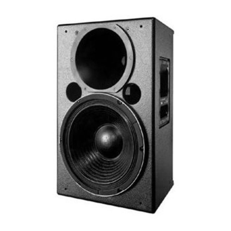
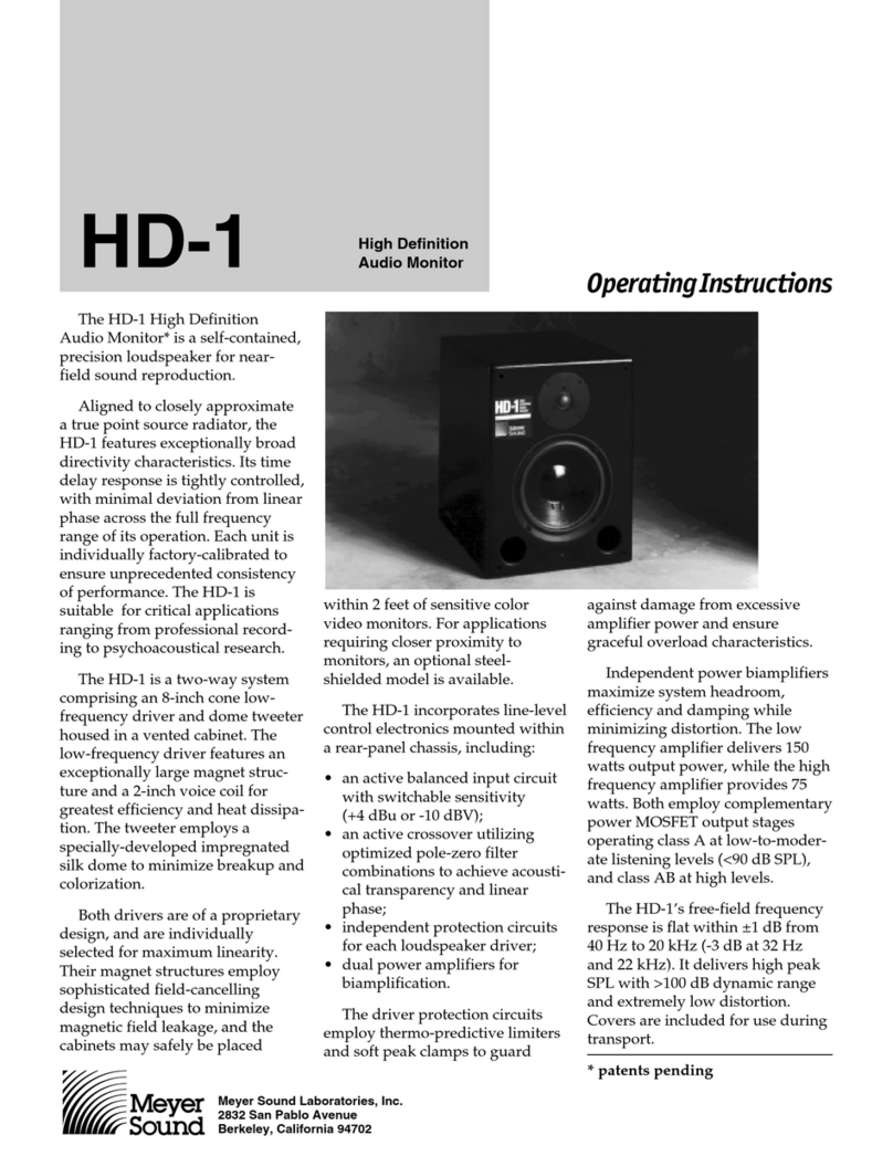
The Meyer Sound USM-1 is a high-powered, wide
coverage loudspeaker for professional stage moni-
toring applications. Specifically designed for tour-
ing reinforcement, the accurate, rugged USM-1 is
a biamplified system consisting of a proprietary 15-
inch low-frequency driver in a vented enclosure,
and a 70-degree high-frequency horn with a 2-inch
(throat diameter) driver.
The USM-1 is designed to be operated as a sys-
tem with the Meyer Sound S-1 Control Electronics
Unit (one S-1 per channel). The S-1 comprises
electronic crossover, Meyer Sound exclusive
SpeakerSense™ driver protection circuitry, and
amplitude and phase response alignment circuitry
optimized for the loudspeaker.
Operating Instructions
Meyer Sound Laboratories, Inc.
2832 San Pablo Avenue
Berkeley, CA 94702
USM-1
The USM-1 requires a professional quality two-
channel power amplifier rated at 300 watts per
channel minimum (and not exceeding 1000 watts
per channel) continuous into 8 ohms. (If two
USM-1’s are to be operated in parallel from the
amplifier, it should be capable of driving 4 ohms.)
Using amplifiers of lower power will not allow the
full power and headroom of the USM-1 to be real-
ized, though this may be acceptable in applications
where high pressure levels are not required. Con-
versely, use of amplifiers rated at significantly more
than 1000 watts per channel may endanger the
loudspeaker, and is not recommended.
For further information on power amplifiers, please
refer to Choosing a Power Amplifier, a Meyer
Sound Technical Note available from your dealer.
Connections The USM-1 is a biamplified system and must be
used with the S-1 Control Electronics Unit. The
S-1 functions as an active crossover, dividing the
input signal into high- and low-frequency compo-
nents.
The connection terminals of the low- and high-
frequency drivers appear on a single Cannon P-
type 4-pin connector located on the rear of the
USM-1 cabinet. The pin assignments for this con-
nector are:
Pin 1 — 15-inch driver, hot
Pin 2 — 15-inch driver, common
Pin 3 — horn driver, common
Pin 4 — horn driver, hot
(When the cabinet is fitted with a Cannon EP-5
connector, Pin 5 is unconnected)
The minimum wire size for connections between
the USM-1 and the power amplifier is 14 gauge.
Note. If you are using standard Meyer Sound
loudspeaker cables and adapters, simply connect
the female end of the loudspeaker cable to the
USM-1, the male end of the cable to the Meyer
Sound pigtail adapter, and the banana connectors
of the adapter to your amplifier outputs. In making
connections between the USM-1 and the amplifier,
be sure to connect the 15-inch driver to the Lo
channel, and the horn driver to the Hi channel.
The adapter banana plugs are color-coded as
follows:
Red — Low frequency driver
Black — High frequency driver
For connections between the S-1 and the power
amplifier, refer to the S-1 Operating Instructions.
Verifying System
Polarity All Meyer Sound loudspeakers are thoroughly
tested in all stages of manufacture, and correct
polarity of individual cabinets is assured. However,
accidental polarity reversal is possible when there
are multiple amplifier connections. A cabinet which
is out of polarity with the rest of the system will
cause severe cancellation, resulting in a noticeable
decrease in SPL and possible component damage.
Because of the extensive signal processing cir-
cuitry of the S-1 Control Electronics Unit, the
“phase-popper” type of speaker checkers cannot
reliably be used to test for correct polarity of the
low and high drivers of the USM-1. However, be-
cause the USM-1 is phase corrected through
crossover, any of the portable spectrum analyzers
can be used, with a pink noise source, to test for
driver polarity as follows:
1. Single Cabinets. First, verify polarity of the
woofer by connecting a 9-volt battery at the end of
the loudspeaker cable.
Amplifier
Requirements
Cannon connector Battery
Pin 1 + terminal
Pin 2 - terminal
• The woofer cone should move outward toward
the listener. Connect the speaker cable to the
amplifier.
• Input the pink noise source to the S-1 and ad-
vance the S-1 input Level control to a conve-
nient measuring level.
• Standing in front of the loudspeaker, position
the analyzer microphone directly between the
horn and the 15-inch driver, at right angles to
the cabinet face, and about twenty inches in
front of the USM-1.
• If polarity of the horn driver is reversed, a trough
will appear in the response curve at around
900 Hz. If in doubt, reverse the polarity of the Hi
amplifier output while you watch the display.
Operating Instructions
Meyer Sound Laboratories, Inc.
2832 San Pablo Avenue
Berkeley, CA 94702
USM-1
2. Multiple Cabinets. Each cabinet should first be
tested as above.
• Connect one loudspeaker and advance the pink
noise to a convenient measuring level. Position
the measuring microphone between the two
adjacent loudspeakers, and about six feet dis-
tant. Note the frequency response and overall
level.
• Leaving the first loudspeaker connected, con-
Placement of the
USM-1 When the USM-1 is placed on the floor in its nor-
mal position (horn facing up towards the per-
former), there will be a boost in the low frequency
response of the loudspeaker. This is caused by the
loudspeaker coupling with the floor, and may be
corrected at the S-1 Control Electronics Unit by
switching in the Lo Cut filter on the Preset Panel, if
desired. Please refer to the S-1 Operating In-
structions for a complete description of its func-
tions.
Rigging The USM-1 loudspeaker has four steel rigging
brackets internally mounted as an integral part of
the cabinet design, and the cabinet is supplied with
aircraft pan fittings (ring and stud), or 3/8"-16 or
M10 x 1.5 nut plates, according to user preference.
A flat plate is supplied when no rigging hardware is
specified. All three plate types are held in place by
six Phillips-head machine screws and can be inter-
changed at any time. The handles on the USM-1
cabinet are provided for moving and carrying
the loudspeaker and are not to be used for
rigging purposes.
The rigging hardware is designed so that a single
point can support the normal load for the cabinet.
In the case of the USM-1, the recommended maxi-
mum load is 420 lbs. (190 kg). Any of the individual
rigging points is capable of supporting this load
with an adequate safety margin. However, Meyer
Sound strongly recommends that safety lines be
run to the other points. If the structural integrity of
any cabinet has been compromised by damage or
negligence, then the safety of the rigging cannot
be assured. All rigging should be done by com-
petent professionals.
nect the adjacent one and observe the analyzer
display. The entire curve should jump up in
level, indicating correct addition between the
loudspeakers. If the loudspeakers are adjacent,
a polarity reversal between them will show up
as severe broadband cancellation.
As the loudspeakers are moved apart, the can-
cellation will become less apparent at high
frequencies. For this reason polarity testing
should be done with cabinets adjacent.
Operating Instructions
Meyer Sound Laboratories, Inc.
2832 San Pablo Avenue
Berkeley, CA 94702
USM-1
Specifications
Notes:
1. Measured 1 meter on-axis to high horn, half-space conditions, pink noise input, in third
octave bands.
2. Loudspeaker driven with "A" weighted noise (peak-to-RMS ratio ≈12dB), with amplifier
rated at 300 W/channel at 8 ohms. The USM-1 will accommodate amplifiers capable of
output levels up to ±140vpk.
3. Refer to "USM-1 Overall Dimensions" for detailed dimensions. (Available from Meyer
Sound Labs. Inc.)
Acoustical - USM-1/S-1 System
Frequency response140-18k Hz ±4 dB
Maximum SPL2
Continuous 130 dB
Peak 139 dB
HF Distribution Pattern
Horizontal 70 degrees
Vertical 60 degrees
USM-1 Loudspeaker
Driver Complement
Low Frequency Driver MS-15
High Frequency Driver MS 2001A
High Frequency Horn 70 degree modified radical
HF DC Protection 20µF Polypropylene capacitor
Enclosure 2.3 cu. ft. vented, multi-ply
Finnish birch plywood
Finish Black textured
Physical Dimensions321" W x 21.5" H x 18" D
Weight 82 lbs. (37.3 kg)
Protective Grill Hex perforated metal, powder
coated, charcoal-grey foam covering
Connector Cannon EP-4 (male)
EP-5 (male, Europe only)
Rigging (optional) Aircraft pan fittings, or M10 x 1.5
or 3/8"-16 nut plate
© 1992,Meyer Sound. 05.151.012.01 A

This manual suits for next models

1

Other Meyer Sound Speakers manuals

Meyer Sound HIGH DEFINITION AUDIO MONITOR HD-1 User manual

Meyer Sound

Meyer Sound HIGH DEFINITION AUDIO MONITOR HD-1 User manual

Meyer Sound MJF-212A User manual

Meyer Sound

Meyer Sound MJF-212A User manual

Meyer Sound UltraCompact High-Power Curvilinear Array Loudspeaker... User manual

Meyer Sound

Meyer Sound UltraCompact High-Power Curvilinear Array Loudspeaker... User manual

Meyer Sound HMS-5 User manual

Meyer Sound

Meyer Sound HMS-5 User manual

Meyer Sound 1100-LFC User manual

Meyer Sound

Meyer Sound 1100-LFC User manual

Meyer Sound UPA-2C User manual

Meyer Sound

Meyer Sound UPA-2C User manual

Meyer Sound 1100-LFC User manual

Meyer Sound

Meyer Sound 1100-LFC User manual

Meyer Sound Self-Powered Reinforcement Loudspeaker MTS-4 User manual

Meyer Sound

Meyer Sound Self-Powered Reinforcement Loudspeaker MTS-4 User manual

Meyer Sound Self-Powered Studio Monitor HM-1S User manual

Meyer Sound

Meyer Sound Self-Powered Studio Monitor HM-1S User manual

Meyer Sound QUICKFLY M Series User manual

Meyer Sound

Meyer Sound QUICKFLY M Series User manual

Meyer Sound MSL-2A User manual

Meyer Sound

Meyer Sound MSL-2A User manual

Meyer Sound CQ-2 User manual

Meyer Sound

Meyer Sound CQ-2 User manual

Meyer Sound AMIE User manual

Meyer Sound

Meyer Sound AMIE User manual

Meyer Sound Stella-8C User manual

Meyer Sound

Meyer Sound Stella-8C User manual

Meyer Sound LEO-M User manual

Meyer Sound

Meyer Sound LEO-M User manual

Meyer Sound DS-4P User manual

Meyer Sound

Meyer Sound DS-4P User manual

Meyer Sound UPA-1P User manual

Meyer Sound

Meyer Sound UPA-1P User manual

Meyer Sound UPQ-1P User manual

Meyer Sound

Meyer Sound UPQ-1P User manual

Meyer Sound Self-Powered Loudspeakers UM-100P User manual

Meyer Sound

Meyer Sound Self-Powered Loudspeakers UM-100P User manual

Meyer Sound UPJunior UltraCompact VariO User manual

Meyer Sound

Meyer Sound UPJunior UltraCompact VariO User manual

Meyer Sound DS-2 User manual

Meyer Sound

Meyer Sound DS-2 User manual

Meyer Sound MM-4CEU User manual

Meyer Sound

Meyer Sound MM-4CEU User manual

Meyer Sound HMS-10 User manual

Meyer Sound

Meyer Sound HMS-10 User manual

Meyer Sound DS-2P User manual

Meyer Sound

Meyer Sound DS-2P User manual

Popular Speakers manuals by other brands

Conquer CQL1570-B instruction manual

Conquer

Conquer CQL1570-B instruction manual

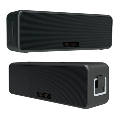
Carlos Santana SANTANA SAMBA manual

Carlos Santana

Carlos Santana SANTANA SAMBA manual

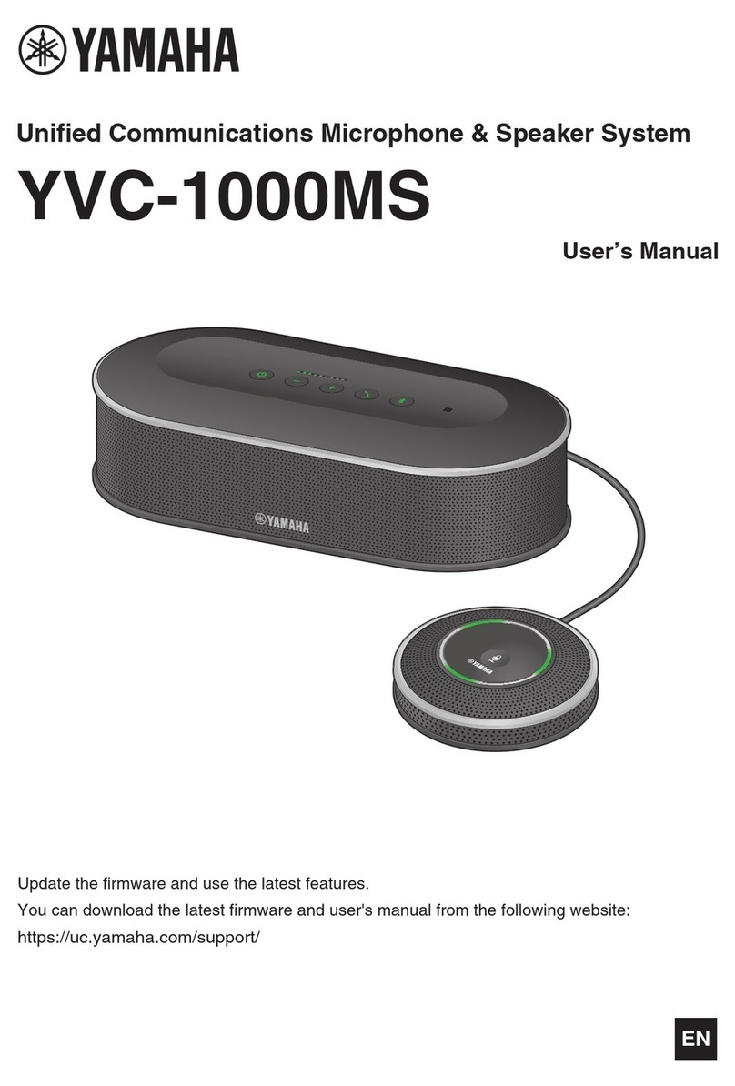
Yamaha YVC-1000MS user manual

Yamaha

Yamaha YVC-1000MS user manual

Audio Pro Ego 515 Technical data

Audio Pro

Audio Pro Ego 515 Technical data

Sony SRS-A3 Specifications

Sony

Sony SRS-A3 Specifications

Niles PHD60 Specifications

Niles

Niles PHD60 Specifications

Madison MAD-HIGHPOWER400 instruction manual

Madison

Madison MAD-HIGHPOWER400 instruction manual

Loewe Compose operating instructions

Loewe

Loewe Compose operating instructions

Wharfedale Pro Reason Series user manual

Wharfedale Pro

Wharfedale Pro Reason Series user manual

Monacor ESP-152/WS operating instructions

Monacor

Monacor ESP-152/WS operating instructions

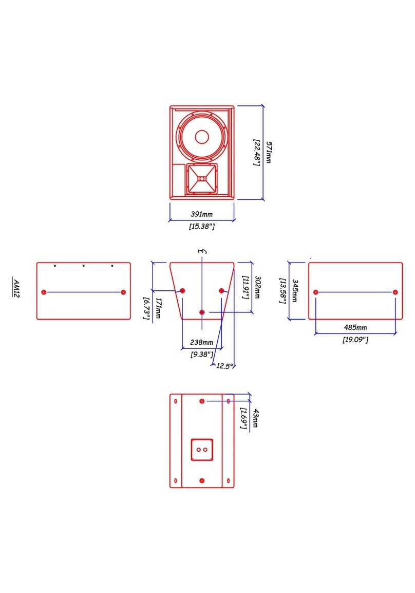
Martin Audio AM12 - SCHEMATICS manual

Martin Audio

Martin Audio AM12 - SCHEMATICS manual

Philips HTL2163B quick start guide

Philips

Philips HTL2163B quick start guide

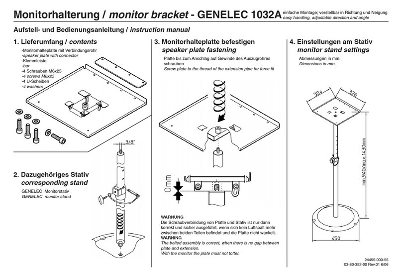
Genelec 1032A instruction manual

Genelec

Genelec 1032A instruction manual

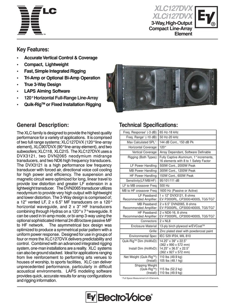
Electro-Voice Xlc Series Xlc-127DVX Technical specifications

Electro-Voice

Electro-Voice Xlc Series Xlc-127DVX Technical specifications

Energy e:XL-16 owner's manual

Energy

Energy e:XL-16 owner's manual

Dutch originals DO-SV-BTSB2-B user manual

Dutch originals

Dutch originals DO-SV-BTSB2-B user manual

Advanced Visual Solutions CPS03 Installation and operating instructions

Advanced Visual Solutions

Advanced Visual Solutions CPS03 Installation and operating instructions

Proficient Audio Systems F400gb owner's manual

Proficient Audio Systems

Proficient Audio Systems F400gb owner's manual

manuals.online logo
manuals.online logoBrands
  • About & Mission
  • Contact us
  • Privacy Policy
  • Terms and Conditions

Copyright 2025 Manuals.Online. All Rights Reserved.