mFi Mason-Lite MFPST43VF User manual

Instructions
Model MFPST43VF
Do not store or use gasoline or other
ammable vapors and liquids in the
vicinity of this or any other appliance.
WHAT TO DO IF YOU SMELL GAS:
• Do not try to light any appliance.
• Do not touch any electrical switch; do
not use any phone in your building.
• Immediately call your gas supplier from
a neighbor’s phone and follow the gas
supplier’s instructions.
• If you cannot reach your gas supplier,
call the re department.
Installation and service must be
performed by a qualied installer, service
agency, or the gas supplier.
WARNING:
If the information in these instructions is
not followed exactly, a re or explosion
may result causing property damage,
personal injury or death.
REV JAN 2021
Vent Free Universal Masonry Firebox
This rebox has been tested and approved by PFS
under ANSI Z21.91 for use with any ANSI Z21.11.2
approved gas logs.
IMPORTANT: READ THESE INSTRUCTIONS
CAREFULLY BEFORE STARTING
INSTALLATION OF THIS FIREPLACE.
Do not store gasoline or other ammable vapors and liquids in the vicinity of this or any other appliance.
This appliance is only for use with the type
of gas indicated on the rating plate. This
appliance is not convertible for use with
other gases, unless a certied kit is used.
Inc.
Report No. 08-154
FOR USE ONLY WITHALISTED GAS-FIRED UNVENTED
DECORATIVE ROOM HEATER NOT TO EXCEED 40,000
BTU/H.
DO NOT BUILD A WOOD FIRE.
Carefully review the instructions supplied with the
decorative type unvented room heater for the minimum
replace size requirement.
DO NOT INSTALL AN APPLIANCE IN THIS FIREBOX
UNLESS THIS FIREBOX MEETS THE MINIMUM
DIMENSIONS REQUIRED FOR THE INSTALLATION.
INSTALLER:Leave this manual with the appliance.
CONSUMER: Retain this manual for future reference.

Exploded Parts Diagram ......................................................................................... Pg. 2
General Information ................................................................................................ Pg. 3
Safety Information ................................................................................................... Pg. 4
Location...................................................................................................................Pg. 5
Supporting Floor Systems....................................................................................... Pg. 5 ~ 6
Mason-Lite Weight Determinations ......................................................................... Pg. 7
Clearances ..............................................................................................................Pg. 7, 8
Air for Combustion and Ventilation.......................................................................... Pg. 9
Important Pre-installation Information ..................................................................... Pg. 10
Fireplace Assembly Procedures.............................................................................. Pg. 11 ~ 13
Gas Piping Installation ............................................................................................ Pg. 13
Electrical Line Feed................................................................................................. Pg. 13
Firebrick Liner Installation ....................................................................................... Pg. 14
Initial Fireplace Operation ....................................................................................... Pg. 14
Appendix I ...............................................................................................................Pg. 15
Appendix II ..............................................................................................................Pg. 16
Warranty Information............................................................................................... Pg. 17
CONTENTSCONTENTS
Below is a sample picture of the rating plate that is located inside the lower dome side of your replace. Model Number, Date of
Manufacture and Serial Number should be stamped on the plate where indicated.
FOR USE WITH LISTED ANSI Z21.11.2 UNVENTED DECORATIVE ROOM
HEATERS NOT TO EXCEED 40,000 BTU/HR (11.723W) CONSULT WITH
INSTRUCTIONS FOR THIS FIREBOX FOR FURTHER INFORMATION.
Refer to installation instructions and check local codes prior to installing. This appliance
must be installed in accordance with local codes if any, if not, in accordance with the
National Fuel Gas Code ANSI Z223.1 installation codes.
01.26.2021
ANSI Z21.91 Ventless Firebox Enclosures for Gas-Fired Unvented Decorated Room Heaters.
0” - 10” : NO PROJECTIONS
10” - 16” : 1-1/2” MAX. PROJ.
16” - 22” : MAX. PROJ.
22” & ABOVE : 10” MAX. PROJ.
DISTANCE FROM SIDE OPENINGS
3” MIN. : 1-3/4” MAX. PROJ.
MANTEL CLEARANCES
MFI
Masonry
Fireplace
Industries, Inc.
6391 Jurupa Ave., Riverside, CA 92514
THIS APPLIANCE NEEDS FRESH AIR FOR SAFE
OPERATION AND MUST BE INSTALLED SO
THERE ARE PROVISIONS FOR ADEQUATE
COMBUSTION AND VENTILATION AIR.
DO NOT REMOVE THIS LABEL
SERIAL No.
LARR No. 25924
MODEL No.:
MFP44VF MFP49VFMFP39VF
DATE OF MFG: BOTTOM 0”
0”
42”
18 1/2”
TOP/
BACK/
SIDES
OPENING
TO CEILING
CLEARANCES TO COMBUSTIBLES
RECESS
DEPTH
MFPST43VF
2.81”
6.500”
.125”
.125”
7. HOLES: 4X Ø.125” THRU
6. CLEAR BOXES NEXT TO MODEL NUMBERS ARE TO BE STAMPED DURING MANUFACTURE OF FIREPLACE.
5. LARGE TEXT TO BOLD UPPERCASE ARIAL, 10 PT. MIN. (WHERE SHOWN).
4. SMALLEST TEXT TO BE ARIAL, 8 PT. MIN (WHERE SHOWN).
3. ALL TEXT AND GRAPHICS TO BE BLACK ON A CONTRASTING, CLEAR ALUMINUM BACKGROUND.
2. FINISH: CLEAR MYLAR TO BE APPLIED ON TOP SURFACE.
1. MATERIAL: CLASS IIIA , .024 THICK ALUMINUM RATED AT 302°F (150°C).
NOTES: UNLESS OTHERWISE SPECIFIED
DESCRIPTION: SERIAL PLATE, VF FIREPLACES
P/N: MFP586
REV: H
DATE: 5/15/2018
LAST MODIFIED BY: CB
Doc File Name: MFP586_RATING PLATE, VF rev H
Tested & Listed By
Report No.
08-154
ICC Evaluation
Services Report
No. 2401

2
Refractory Firebrick Liners
(Herringbone Pattern shown, also available
in Running Bond - see Pg.16)
MFPST43 SHBL- Herringbone
MFPST43 FRBL- Running Bond
Exploded Parts DiagramExploded Parts Diagram
Figure 1
Exploded Diagram
WARNING
Failure to position the parts in
accordance with these diagrams or
failure to use only parts specically
approved with this appliance may result
in property damage or personal injury.
Customer Service & Parts Replacement
Parts and accessories may be purchased from your local
dealer. Additional information is available from Masonry
Fireplace Industries Inc. Accessory orders will be accepted
by mail, or you may call your order in at: (800)-345-7078.
ITEM DESCRIPTION QTY
1HEARTH 2
2SIDE WALL 8
3LOWER SIDE DOME 2
453” x 4” x 3” x 1/4” ANGLE IRON 2
5LOWER DOME FRONT 2
6LINTEL 2
7DOME TOP 2
8RATING PLATE 1
9#3 REBAR (Ø3/8”)
7
6
5
4
2
1
9
8
3
ITEM NO.
PART NUMBER
DESCRIPTION
QTY.
1
MFPST43 HEARTH BTM
RV2 [MFP401]
HEARTH BTM
2
2
MFPST-43 SIDE WALL2
SIDE WALL, MFP-49ST
8
3
MFP49-7
LOWER SIDE DOME
2
4
MFPST43 ANGLE IRON
2
5
MGFPST43 LOWER
DOME FRONT
LOWER DOME
2
6
LINTEL FRONT
MGFPST43
LINTEL, FRONT
2
7
MFPST43VF DOME
TOP
2
8
MFP416
PLATE, RATING, MFPST43
1
9
REBAR No3 MFP49-11
#3 REBAR (Ø3/8") x 36"
4
QTY of rebar:
Six (4) pieces 3/8” rebar x 34” long (included with unit)
Six (4) pieces 3/8” rebar x 12” long (included with unit)

3
General InformationGeneral Information
Introduction
We extend a warm welcome from all of us at Masonry
Fireplace Industries, Inc. (MFI), proud manufacturers of
Mason-Lite Fireplaces.
Thank you for Choosing MFI.
You may have thought long and hard before you chose the
replace which would grace your home. Rest assured that
every component of the Fireplace has been tested to ensure
long-term durability.
Before Beginning the Installation
Read these instructions carefully before beginning the
installation of this Vent-Free replace. Also read the gas
log appliance manufacturer’s literature regarding sizing
and suitability for installation into this Enclosure prior to
installation.
Statement of Intended Use:
The Mason-Lite Vent-Free Universal Masonry Fireplace is a
modular refractory masonry unit designed for eld assembly.
The rebox is constructed using pre-cast, interlocking
refractory blocks. The blocks are then secured to each other
using Mortar. The system includes all parts necessary for the
assembly of a complete masonry vent-free decorative gas log
enclosure.
In addition to the basic enclosure, a standard 1-1/8” thick,
high temperature refractory brick is required to line the interior
of the rebox.
These replaces are not intended to serve as a primary
heat source, rather, the replace was expressly created as a
supplemental source of heat.
The MASON-LITE is Designed to be used ONLY with
approved Vent-Free Decorative Gas Log sets meeting
standard ANSI Z21.11.2
Vent free decorative gas log sets meeting standard ANSI
Z21.11.2, are supplied by others and are limited to any listed
vent-free gas-red log sets with heat input ratings up to
40,000 Btu/hr.
WARNING: Any application other than the “Intended Use” as
stated above is in violation of the manufacturer’s instructions
and is hereby prohibited. Such violation may cause immediate
hazard, property damage or loss of life and will void all
liabilities to the manufacturer and will void all warranties
explicit or implied.
Product Overview
Mason-Lite replaces are designed as Factory Built - Field
Assembled Fireplaces to be installed on both combustible and
non-combustible oor systems. They have been extensively
tested to perform with excellent results in this environment.
Attention: Be advised that all the illustrations in this manual
are for general reference only. They are not drawn to scale.
Actual design elements will vary from case to case. Pay
attention to specied minimum clearances as they relate to
combustible materials.
53"
43"
32" 46" 38"
2 1/4"
28"
Figure 2
Overall Dimensions
ALL DIMENSIONS ARE IN INCHES.
* VERTICAL DIMS. ARE DRY STACK MIN., MORTAR
THICKNESS MAY ADD A TOTAL OF 1 INCH TO
OVERALL HEIGHT.

4
Safety InformationSafety Information
Carbon Monoxide Poisoning: Early signs of carbon monoxide
poisoning resemble the u, with headaches, dizziness, or
nausea. If you have these signs, the replace may not be
working properly. Get fresh air at once! Have the replace
serviced.
Note: Some people are aected more than others by carbon
monoxide. These may include pregnant women, people with
heart or lung disease, are anemic, anyone under the inuence
of alcohol, and those at high altitude.
IMPORTANT: Read this owners manual carefully
and completely before trying to assemble, operate,
or service this replace. Improper use of this
replace can cause serious injury or death from
burns, re, explosion, electrical shock, and carbon
monoxide poisoning.
General Safety Concerns
1. If you smell gas
l Shut o gas supply.
lDo not try to light any appliance.
lDo not touch any electrical switch; do not use any
phone in your building.
l immediately call your gas supplier from a neighbor’s
phone. Follow the gas supplier’s instructions.
l If you cannot reach your gas supplier, call the re
department.
2. This replace shall not be installed in a bedroom or
bathroom.
3. Never install the replace
l In a recreational vehicle.
l Where curtains, furniture, clothing, or other ammable
objects are less than 36 inches from the front, top, or
sides of the replace.
l In high trac areas.
l In windy or drafty areas.
4. Do not use this replace as a wood-burning replace.
5. Do not add extra logs or ornaments such as pine cones,
vermiculite, or rock wool. Using these added items can
cause soot build-up.
6. This replace is designed to be smokeless. If logs appear
to smoke, turn o replace and call a qualied service
person.
7. Avoid any drafts that alter burner ame patterns. Do not
allow fans to blow directly into the replace. Do not place
a blower inside burn area of the rebox. Ceiling fans may
create drafts that alter burner ame patterns. Soot build-up
and improper burning will occur. Soot build-up can settle
on household surfaces outside the replace.
8. This replace needs fresh air ventilation to run properly.
The Vent free decorative gas log set must have an
oxygen depletion sensor (ODS) pilot light safety system.
The ODS shuts down the replace if not enough fresh
air is available. See Air for Combustion and Ventilation,
page 10. If the replace keeps shutting o, see appliance
manufacturers’ troubleshooting instructions.
9. Do not run replace
l Where ammable liquids or vapors are used or stored.
l Under dusty conditions.
10. Do not use this replace to cook food or burn paper or
other objects.
11. Never place any objects in the replace or on logs.
12. Fireplace glass doors are not permitted in this decorative
room heater. Fireplace front becomes very hot when
running replace. Keep children and adults away from hot
surfaces to avoid burns or clothing ignition. The replace
will remain hot for a time after shut down. Allow surfaces
to cool before touching.
13. Carefully supervise young children when they are in the
room with the replace.
14. Do not use replace if any part has been exposed to or
under water. Immediately call a qualied service technician
to inspect the replace and to replace any part of the control
system and gas control which has been under water.
15. Do not operate the replace if any log is broken. Do not
operate the replace if a log is chipped (dime-sized or
larger). Verify proper log placement prior to operating
appliance.
16. Turn replace o and let cool before servicing. Only a
qualied service person should service and repair the
replace.
17. Operating the replace above elevations of 4,500 feet
may cause pilot outage.
DO NOT USE OR STORE GASOLINE OR OTHER
FLAMMABLE LIQUIDS OR GASES IN OR NEAR THE
FIREPLACE!
ATTENTION: A re or an explosion could occur causing property
damage, injury or loss of life if you do not follow the information
in this manual!
NOTE: THIS MANUAL MUST BE REPRODUCED ONLY IN
ITS ENTIRETY.
DANGER:
Carbon monoxide poisoning may lead to
death!

5
Carefully review the instructions supplied with the decorative
type unvented room heater for the minimum rebox size
requirement.
DO NOT INSTALL THE APPLIANCE IN THIS
FIREBOX UNLESS THIS FIREBOX MEETS THE
MINIMUM DIMENSIONS REQUIRED FOR THE
INSTALLATION.
IMPORTANT: Vent-free heaters add moisture to the air.
Installing a replace in rooms without enough ventilation air
may cause mildew to form from too much moisture.
IMPORTANT: Make sure the replace is level. If the replace is
not level, the log set will not work properly.
Attention: You may need a building permit to install a MASON-
LITE replace. Check with the local jurisdiction before you get
started.
LocationLocation
When choosing a location for your replace, avoid locations
that are subject to too much draft or locations where you may
encounter obstructions that may be in the way of the replace
once installed. Always check local codes and familiarize yourself
with the surrounding construction.
The MFPST43VF See-Thru Fireplace requires either an internal
wall or island installation which provides a discreet option for
room separation and can also be ideal as an addition to an
existing wall.
Internal
Wall
Installation
Island
Installation
Figure 3
W
*H
D
Figure 4
*Height may vary. Maintain 1/2 inch clearance to top of
lintel (see Fig.12).
Model W H D
MFPST43VF 53” *40” nominal 28”
Supporting Floor Systems
Floor Framing
It is important to take into consideration that the load for the
Mason-Lite Fireplace is considerable, but, more important, that
it is a dead load that will have to be absorbed by a relatively
small amount of existing oor space.
It is the ultimate responsibility of the installer to ensure that
proper concrete slab supports are used.
WARNING to the licensed design professional and/or building
contractor: It is your responsibility to be certain that the Mason-
Lite can be properly supported by the combustible oor system
on which the replace will rest.
For replace support foundations installed on concrete refer to
Appendix I and II (pages 15 & 16) for specic instructions.
Wood Floor
Anchorage of replace to wood oor construction is required.
Refer to Figure 10 for anchorage dimensions. Four anchors are
required to attach to the sub-ooring framing.
Crawl Space or Upper Floor:
For installation of rebox over combustible crawl spaces or
upper oors, anchorage of the rebox is required. Illustrations
of examples of possible anchorage methods are shown in
Figures 5 thru 7 depending upon the type of oor framing. Final
method of anchorage is to be determined by licensed design
professional.

6
Figure 5
Floor Sheathing
not shown for
clarity
Anchor Bracket
Assembly
EXAMPLE ONLY
2X FLOOR JOIST
2X FLOOR JOIST
A35 Brackets
(16 required)
For conventional framing, where the oor joists are parallel
with the sides of the rebox, the addition of oor joists to align
with the anchor brackets allows the brackets to be directly
connected to the oor joists.
Note that additional oor joists may be required to support
the weight of the rebox and chimney. Where the oor joists
run parallel to the front of the rebox, anchorage can be
accomplished in like manner as shown in Figure 5 using
blocking between the oor joist.
For oors supported by I-Joists, the method of anchorage is
illustrated in Figures 6 and 7. Figure 10 illustrates the general
arrangement of anchorage to oor framing.
I-Joist
Simpson
Strong-Tie
A-35 or
equivalent
Figure 6
I-Joist Anchoring
Top View
Example Only
I-JOISTS
Anchor
Brackets
Figure 7
I-Joist
Anchoring
Bottom
View
Example Only
It is important to take into consideration that the load for
the Mason-Lite Fireplace must be considered as additional
dead load that will have to be supported by the oor framing.
Additional oor joists or I-joists may be required as determined
by the licensed design professional.
The dead weights for the replace are noted in Table I. It is
the task and responsibility of the general contractor/installer to
see that the proper reinforcement for weight loads are made by
a licensed design professional prior to the replace installation.
As stated above, it is desirable to place additional framing
for alignment of anchor rods. Refer to Figure 10 for anchor rod
locations.
53"
43"
32" 46" 38"
2 1/4"
28"
11"
48"
Figure 8
Figure 9

7
Fireplace
outline
10”
Typical Anchorage
Layout
EXAMPLE ONLY
SECTION VIEW
ROTATED 90CW
Figure 10
Mason-Lite Weight DeterminationsMason-Lite Weight Determinations
The following are dead load weight estimates for the Mason-
Lite Fireplace.
Table I
Fireplace Model MFPST43VF
Fireplace Weight 974 lbs.
Mortar, Rebar &
Ready Mix Concrete 356 lbs.
Firebrick Lining 293 lbs.
Floor Area 53” x 28” (10.3 ft²)
Other Weight Considerations:
Fireplace nished facing (surround): This information needs to
be obtained from the contractor.
Table II - Deection Limits
Construction L S or W D +L1
Floor Members I/360 --- I/240
1For wood structural members having a moisture content of
less than 16 per cent at time of installation and used under dry
conditions, the deection resulting from L + 0.5D is permitted to
be substituted for the deection resulting from L + D.
Note that MASON-LITE cannot accept responsibility for
structural oor support details. All drawings are presented as
mere illustrations to indicate the presence of the underlying
oor system. It is the responsibility of the general contractor/
installer to consult with a local licensed design professional for
guidance in building a proper oor support system.
ClearancesClearances
The Importance of Clearances
Warning to the structural engineer and/or building contractor: It
is your responsibility to be certain that the Mason-Lite can be
properly supported by the combustible oor system on which
the replace will rest. Be advised that this engineering equation
will be in addition to any live or dead weights that the oor has
to carry.
Clearances to Combustibles
Nothing is more important than paying strict attention to
giving clearance between replace surfaces and surrounding
“combustibles” the most common of which are:
l Drywall
l Wood ooring
l Plywood sub-ooring
l Framing materials
l Particle board
l Mill board
l Plywood paneling
Required Clearances are:
Unit front, sides, rear: .......................................... 0"
Combustible Floor: .............................................0"
Combustible Sheathing above opening top: .......8" (200 mm)
Sheathing or trim to opening sides: ....................8" (200 mm)
Mantle above opening: .......................................12" (300 mm)
Opening to sidewall: ...........................................24" (500 mm)
Insulation from rebox: ....................................... 0"
The Mason-Lite Vent-Free replace may be installed at
“zero clearance” to plywood sheathing and to uninsulated wood
framing members at the unit bottom, sides, rear and top when
used for enclosing any listed vent-free gas-red log set with
maximum heat input ratings up to 40,000 Btu/hr. However,
when a Vent-Free replace is to be installed on carpeting, wood
ooring, or any combustible material other than tile or concrete,

8
the Vent-Free replace shall then be installed on a metal or
wood platform extending the full width and depth of the Vent-
Free replace.
Clearance to Combustible Trim:
Mason-Lite Vent-Free Fireplaces are designed to be custom
nished with facing trim and mantle to be an owner option.
However, all such trim material must meet standard replace
code requirements.
Non-combustible facing material must be applied to a
minimum of eight inches (8”) beyond the sides of the nished
opening of the Vent-Free replace and non-combustible facing
material must cover a minimum of twelve inches (12”) above
the nished opening of the installed unit.
11
2"
24" min 8” MIN.
Non-combustible
Material Figure 11
Clearance to combustible trim are those distances required
to ensure that combustible mantle and facing material will not
be exposed to excessive heat while the unit is operating.
These clearances should be adequate to prevent
discoloration or warping of trim facings due to heat. However,
circumstances unique to each installation create variables that
may be beyond the scope of this manual. Therefore be sure
to follow gas log appliance manufacturer’s explicit installation
instructions regarding all minimum trim facing, mantle height
and side wall clearance requirements.
Parts of the combustible mantle assembly located above
and projecting more than one and one-half inches (1-1/2”)
inches from the rebox opening shall be kept at least twelve
inches (12”) from the top of the opening.
12"
NON-COMBUSTIBLE
ONLY ZONE
20" MIN
1 1/2"
10"
SAFE ZONE FOR
PROJECTION OF
COMBUSTIBLE
MATERIAL
TOP OF FIREPLACE OPENING
MANTEL
LINTEL FRONT
UNVENTED
FIREPLACE
DOME TOP
ALLOW 1/2" MIN
CLEARANCE
Figure 12
Mantle shelves with horizontal projection of ten inches (10”)
from the face of the replace must be held to a minimum vertical
distance of twenty inches (20”) from the top of the nished
replace opening.
Note:Mantle height clearances may vary among gas log
appliance manufacturers or with the use of rebox canopies.
Be sure to follow the gas log appliance manufacturer’s
explicit installation instructions for mantle height clearance
requirements.
Interior Wall Materials:
Wall materials, such as drywall, should be set ush with
the rough front face of the Vent-Free replace. This will allow
for placement of required non-combustible surround material in
such a way that the surround material can lay at against the
nished wall surface and also align with the leading edge of the
re brick interior of the Vent-Free replace (see Figure 15).
Trim Facings:
Parts of the combustible mantle assembly located along the
sides of the rebox opening, which project more than one and
one-half inches (1-1/2”) from the face of the replace, shall be
kept at least eight inches (8”) from the rebox opening.
Adjoining Room Walls:
Interior wall surfaces of adjoining room walls must be at a
minimum horizontal measure of twenty four inches (24”) away
from the nished opening of the Vent-Free replace.

9
Air for Combustion and VentilationAir for Combustion and Ventilation
Energy ecient homes require homes to be airtight but at the
same time provide sucient fresh air to breathe. Fresh air
enters the home through air conditioning duct vents, around
doors and windows but also must provide enough fresh air for
proper combustion on all fuel-burning appliances in the home.
Exhaust fans, replaces, clothes dryers, and fuel-burning
appliances draw air from the house to operate. You must
provide adequate fresh air for these appliances. This will insure
proper venting of vented fuel-burning appliances.
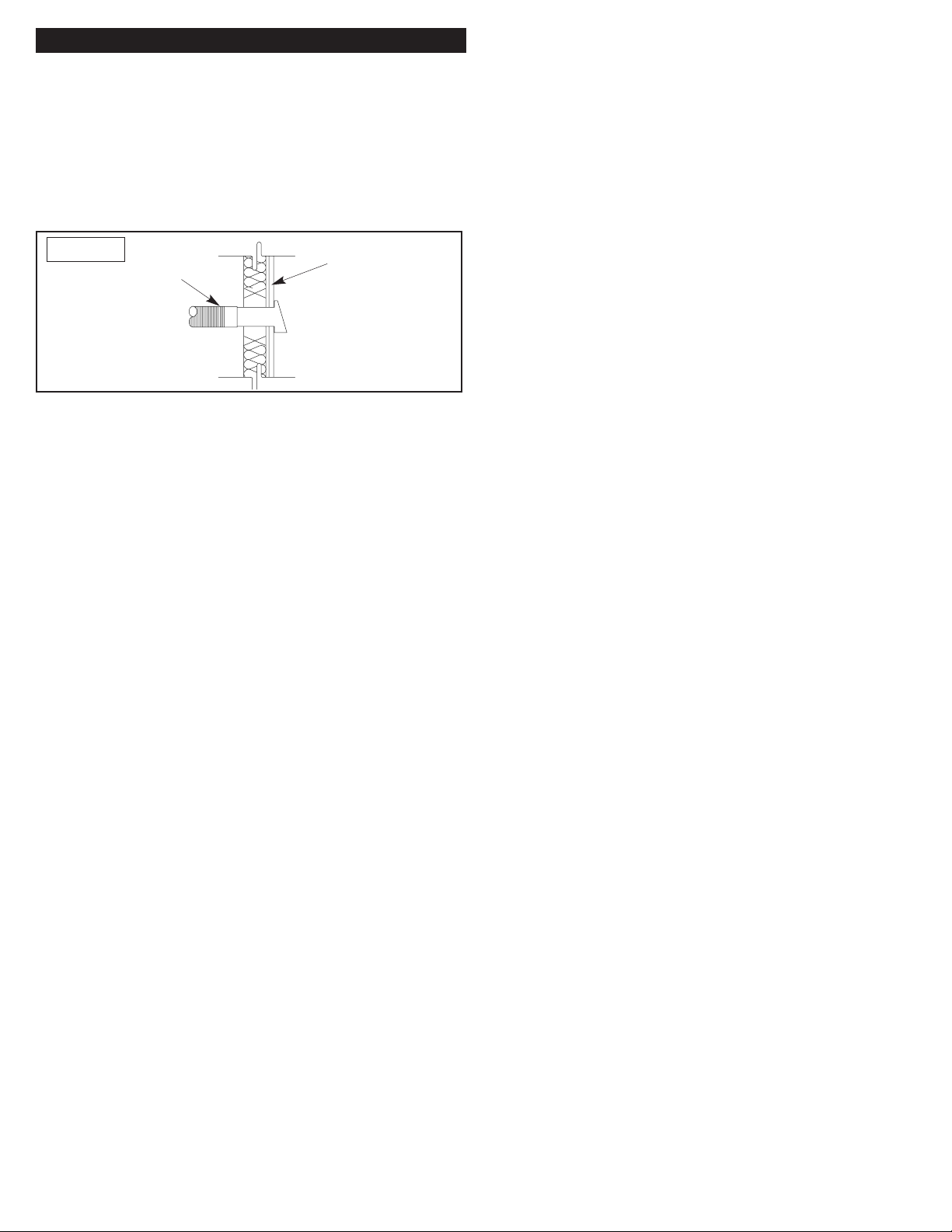
Non-combustible
Flex Hose
Figure 13 Exterior
Providing Adequate Ventilation
In accordance with the National Fuel Gas Code NFPA 54/ANSI
Z223.1, Section 5.3, Air for Combustion and Ventilation, all
spaces in homes fall into one of the three following ventilation
classications:
1. Unusually Tight Construction
2. Unconned Space
3. Conned Space
The following information will help you classify your space and
provide adequate ventilation.
IMPORTANT: Outside Air Kits are not approved for use with
this replace intended for Unvented Gas Logs. Installing an Air
Kit through the side wall of the replace may aect the proper
function of the ODS pilot system.
Unusually Tight Construction
The air that leaks around doors and windows may provide
enough fresh air for combustion and ventilation. However,
in homes of unusually tight construction, you must provide
additional fresh air. Unusually tight construction is dened as
construction where:
a. Walls and ceilings exposed to the outside atmosphere have
a continuous water vapor retarder with a rating of one perm*
or less with openings gasketed or sealed and...
b. Weather stripping has been added on openable windows and
doors and...
c. Caulking or sealants are applied to areas such as joints
around window and door frames, between sole plates and
oors, between wall-ceiling joints, between wall panels, at
penetrations for plumbing, electrical, and gas lines, and
other openings.
* A perm is a unit of permeance or water vapor transmission,
the US perm-inch is dened as the passage of 1 grain of vapor
through 1 square foot of 1 inch thick material in 1 hour under a
pressure dierence of 1 inch of mercury.
If your home meets all the three criteria above, you must provide
additional fresh air.
Unconned Space
An unconned space has a minimum total air volume of
50 cu.ft. (cubic feet) for each 1,000 Btu/Hr input rating of all
appliances in the total space (cu.ft. = length x width x height
of space). Include adjoining rooms only if there are doorless
passageways or ventilation grills between the rooms. If the Btu
per 50 cu.ft. is less than 1,000 Btu/Hr, then fresh air will be
provided by the natural air ow into the house.
Conned Space
A conned space has an air volume of less than 50 cu.ft. for
each 1,000 Btu/Hr input rating of all appliances in the space (cu.
ft. = length x width x height of space). Include adjoining rooms
only if there are door less passageways or ventilation grills
between the rooms.
Determining Total Air Volume
Use this work sheet to determine if you have a conned
or unconned space. The space to be considered includes not
only the room in which you will install the replace but also any
adjoining rooms with ventilation grills between them or door
less passageways.
1. Determine the total volume of your space
L x W x H = _______ cu.ft.
Example: Space size = 20 ft. long x 20 ft. wide x 8 ft. high
(ceiling height) = 3,200 cu.ft.
If adjoining ventilation to adjoining room is supplied with
grills or openings, add the volume of these rooms to the total
volume of the space.
2. Divide the space volume by 50 cu.ft. to determine the
maximum Btu/Hr the space can support.
_______ cu.ft. (volume of space)
50 cu ft. = (Maximum Btu/Hr the space can support)
Example: 3200 cu ft. (Volume of space) / 50 cu. Ft. = 64.0 or
64,000 (maximum Btu/Hr the space can support.)
3. Add the Btu/Hr of all fuel burning appliances in the space.
Vent-free replace _______ Btu/hr
Gas water heater* _______ Btu/hr
Gas furnace _______ Btu/hr
Vented gas heater _______ Btu/hr
Gas replace logs _______ Btu/hr
Other gas appliances* _______ Btu/hr
Total = _______ Btu/hr
Example: Gas water heater 40,000 Btu/hr
Vent-free replace +36,000 Btu/hr
Total = 76,000 Btu/hr
* Do not include direct-vented gas appliances. Direct vent draws
combustion air from the outdoors and vents to the outdoors.

10
4. Compare the maximum Btu/Hr the space can support with
the actual amount of Btu/Hr used.
_________ Btu/Hr (maximum the space can support)
_________ Btu/Hr (actual amount of Btu/Hr used)
Example:
64,000 Btu/Hr (maximum the space can support)
76,000 Btu/Hr (actual amount of Btu/Hr used)
The space in the previous example was a conned space
because the actual Btu/Hr used was more than the maximum
Btu/Hr the space could support. If you nd you have a Conned
Space, you must provide additional fresh air. Your options are
as follows:
a) Re-work worksheet, adding the space of an adjoining room
that may not have qualied for the extra volume. If the extra
space provides enough volume to convert the area to an
unconned space, remove door to adjoining room or add
ventilation grills between rooms.
b) Vent room directly to the outdoors.
c) Install a lower Btu/Hr gas log (if lower Btu/Hr size makes
room unconned).
If the actual Btu/Hr used is less than the maximum Btu/Hr the
space can support, the space is an unconned space. You will
need no additional fresh air ventilation.
WARNING:If the area in which the heater may be operated
is smaller than that dened as an unconned space, provide
adequate combustion and ventilation air by one of the methods
described in the National Fuel Gas Code, ANSI Z223.1 Section
5.3 or applicable local codes.
Local codes may have stricter denitions for conned space
and/or for unusually tight construction. Check you local codes.
IMPORTANT:Do not provide openings for inlet or outlet air
into an attic if the attic has a thermostat-controlled power vent.
Heated air entering the attic will activate the power vent.
Important Pre-installation InformationImportant Pre-installation Information
Overview
You will nd that the Mason-Lite Fireplace is designed for
complete assembly at your construction site with all necessary
items delivered consisting of interlocking precast parts, 50 lbs.
of Mason-Lite mortar and rebar.
The parts of the replace are made of Mason-Lite’s incredibly
strong blend of specialty cement and a lightweight aggregate.
The design of the replace calls for the installation of a refractory
re brick liner. This should be a minimum of 1-1/8” thick. The
liner will be applied within the walls of the rebox. Modular
rebrick panels are also available from MFI.
Additional Materials Required:
1) Ready-Mix concrete - 2 cu.ft.
SURFACE CRACKS - The MASON-LITE FIREPLACES are
manufactured using high quality materials. During the drying
process, surface cracking may occur. These small cracks
(under 1/16” will not aect the replace safety or performance).
During the assembly process, ll surface cracks with thin-set
mortar and brush when drying for a smooth surface nish.
Leveling and Aligning Components:
It is important to assemble all Vent-Free replace components
ush, level and square. Since it is not intended that mortar
be used to lay a mortar joint of any measurable thickness as
is typical when laying brick or concrete block, adjustments in
component height and level alignments are accomplished with
the use of small shims. These shims can be tapped into place
to level and align components. Once the Mason-Lite Mortar is
set, the shims must be removed completely.
Be sure to re-grout any and all gaps where shims have been
inserted and then removed or where contact surfaces have
been separated by shim leveling.
Field Assembly Procedures
1) Mixing the MASON-LITE mortar – You will require a 50 lb.
bucket of MASON-LITE mortar which will be more than
enough to adequately ax all the replace components,
one to the next. The mortar is premixed and dry and
is to be used to adhere all the replace components.
Be sure to use clean water and work it up into a mixture that
is pasty but not lumpy. If it is too thin, the components will
not adhere. Some trial and error may be necessary. You will
want to apply the mixture with a standard grout bag.
2) Moisten all surfaces which will have grout applied prior
to assembly. This will minimize shrinkage and cracks
developing in the joint areas. Best way to accomplish this is
with a bucket of water and a large sponge. Dip sponge into
water and apply a liberal amount of water to the grout joint
surface several minutes before the part is to be assembled.
The water will absorb into the surface allowing the grout to
properly cure.
3) Assembly of the Components – Once you have found the
proper consistency of the mixture, load it into the grout

11
bag and then place the components together applying
the mixture directly to the components where they come
together. As a rule, you can gure that you should lay down
about ½” (one-half inch) of a thread of mortar. The line of
mortar should be approximately ½” (one-half inch) away
from all the edges of each separate component.
The mortar has a considerable amount of holding power so
do not overload the components with too much mortar.
4) You will notice that some mortar will “ooze out” when you
place the next component on top of or next to the component
you previously place. This is to be expected – it means the
two pieces have properly bonded -- and you will want to
swipe the excess away with a trowel. It is never intended
that the surfaces of the MASON-LITE components are to be
completely covered with mortar.
5) Do not apply the mortar in thick bands even if the component
you are working with is larger than the rest. You will want to
apply “stripes” of mortar in these situations.
6) Making Sure Components Are Level – It is extremely
important that you pay careful attention to how you are
assembling the MASON-LITE. Since every component
builds on the next, it is critical, that from the beginning, you are
checking that the components are tting together to be level
and ush. If you have to make any kind of an adjustment, do
not try to do it “by loading an opening” with mortar. That is
completely unacceptable, resulting in a replace that will not
be plumb or level. What you are advised to do is make use
of shims. You will nd these supplied with the MASON-LITE
and you can nudge them in between openings to achieve
the precision you need in making component adjustments.
7) Once you have removed the shims, you will want to cover
any gaps that may have resulted with the grout.
Warning: All surfaces where grout is applied must
have water sponged on several minutes prior to
assembly. This will minimize cracking of grout joint
and provide maximum strength.
Fireplace Assembly ProceduresFireplace Assembly Procedures
Note - Wipe excess water from surface prior to applying grout.
This will help grout to adhere to surface during assembly.
Place the Mason-Lite Fireplace hearth base on top of your non-
combustible oor. For concrete slabs, supporting oor needs to
be rated at ASTM 90.
1) Place the two pieces of hearth in position. Draw an outline
of the hearth area and mark rebar center locations using
holes as template (Figure 15). Drill holes where the rebar
will be located. Secure the #3 rebar 4 inches into the
concrete foundation with ITW Epoxy or Simpson Epoxy.
Follow manufacturer’s instructions for installation of rebar
into slab.
Drill Ø5/8” hole
x 4” deep
Epoxy #3 rebar
centered into hole.
Use ITW Epoxy or
Simpson Epoxy.
For concrete
foundations
less than 6”
thick, drill
slanted.
Figure 14
28”
53”
Apply mortar
between joints
12 inch rebar
Figure 15
2) Mix a batch of mortar and prepare a Hearth bottom surface
to be bonded as shown in Figure 16.
1/2” MORTAR
BEAD TYPICAL
1/2” AWAY
FROM EDGES
APPLY MORTAR
BEAD TO ALL
MATING SURFACES
Figure 16

12
3) Position Hearth to the outline created. The overall width
should allow for an approximate gap of 1/8” between slabs
for the additional mortar to unite the remaining slab. Check
for surface atness, level if necessary.
4) Apply mortar to the remaining Hearth except this time apply
beading on other side to be facing oor as shown in Figure
17.
1/2” MORTAR
BEAD TYPICAL
1/2” AWAY
FROM EDGES
APPLY MORTAR
BEAD TO ALL
MATING SURFACES
Figure 17
5) Prepare side wall mating surface with the prepared mortar
and begin assembly.
Figure 18
1/2” BEAD,
1/2” AWAY
FROM EDGES
6) Keep the assembly of the next sections of the rebox side
walls moving up, keeping components moist, mixing mortar
as you need it and threading the mortar appropriately as
you stack each section, one onto the next. Constantly check
for squareness and levelness while building each course of
block. As you complete each section, make certain that you
adhere the mortar at each and every joint.
Figure 19
Setting Firebox Sides
7) Although you are cautioned to use Mason-Lite mortar
sparingly because it does have such holding power, you
should look over the rebox assembly at the end and
ll any gaps with mortar especially at joint connections.
Adjustments must be made to ensure the replace is level
and square while the mortar is still wet.
8) After fourth row of walls are in place, add 36” rebar to all
cells as shown in Figure 20. The rebar should enter the
holes in the Hearth and lie adjacent to the 12” rebar
secured in suboor. Then ll cells with approx. 2 cu.ft.
Ready-Mix Concrete.
Figure 20
12 inch
rebar
Add 36” rebar
after fourth row
9) Temporarily place Lintels, Dome Fronts and Angle Irons in
position so that the Lintel fronts are ush to the front of the
side walls as shown in Figure 21. Check for alignment.
Figure 21
Angle Iron
Dome
Front
Lintel
10) Place Side Domes between Angle Irons to verify t. The
face with the rating plate faces the inside of the rebox as
shown in Figure 22. Remove and prepare mating surfaces
with mortar. Assemble Dome Sides and check that all four
top surfaces are level with each other. Shim if necessary.
Figure 22
Rating Plate
faces inside
All four top
surfaces to
be level
Lintel front
to be ush to
front face

13
12) Now install the Smoke Dome Tops. Align outer edges with
Lower Dome Sides. Check for atness and squareness.
Figure 23
Raised and Flush Hearth Application:
If you would prefer to have a raised hearth, the Vent-Free
box can be raised to the desired height using wood studs or
concrete blocks.
Figure 24
Concrete Block
Raised Platform
When determining raised hearth height, be sure to
allow for the 3” thick rebox hearth and 1-1/2” thick rebrick
oor, in addition to the height of base platform.
Figure 25
Raised Wood
Platform
For a “ush hearth” (replace oor ush with the room’s
oor) the base plate can be omitted from the assembly and the
rebox walls built directly on the concrete support slab. The
re brick oor of the rebox is then set directly to the concrete
support slab. This makes the replace nished re brick oor
approximately one and one-half inches (1-1/2”) above the top
of the concrete support slab.
Gas Piping InstallationGas Piping Installation
The provision for installation of a gas pipe is only for
connection to a Vent free decorative gas log sets meeting
standard ANSI Z21.11.2
Familiarize yourself with requirements for installation as
outlined by the National Fuel Gas Code, ANSI Z223.1.
This gas pipe provision must only be connected to an
approved vent-free gas log heater certied to ANSI Z21.11.2
heater standard. Check local building codes for specic pipe
and material requirements.
1) Gas piping can be routed from the oor, rear or side walls.
With a masonry drill, follow the instructions from the gas
appliance manufacturer. Any wires must be routed through
separate conduit. Make sure provisions are made for
access to manual shut-o valve.
Figure 26 CSA Certied Manual
Shut-o Valve
Tee-joint
Sediment
Trap
Approved
Flexible
Gas Line 3”
Minimum
Pipe
Nipple
Cap
From External
Regulator
(11-14” W.C. pressure)
2) After routing piping, ll hole around pipe with MASON-LITE
mortar.
Electrical Line FeedElectrical Line Feed
Electrical line feed can be routed through the Standard
rebox back wall, side walls or oor by drilling an appropriately
sized hole using a masonry drill bit. Be sure to follow the
Vent free decorative gas log Manufacturer’s explicit electrical
line connection instructions for vented masonry replace
installations.
NOTE: Gas line and electric line must be routed through
separate access holes.
Firebrick SideGas or
Electric Line
Figure 27
IMPORTANT: All access holes must be grouted with mortar to
seal any gaps or cracks.

14
Firebrick Liner InstallationFirebrick Liner Installation
It is required that the interior sides, rear and bottom be lined
with minimum 1-1/8” thick rebrick. Mason-Lite Pre-fabricated
re brick liner walls can make the installation easier.
All required through-wall accesses (gas and electrical
line feeds and combustion air supply access holes) should be
drilled before the required re brick lining is installed.
Modular Firebrick Lining
If using our Mason-Lite Firebrick Liners, simply use an extra
bucket of mortar. Install Hearth Liner rst, rear next and sides
last. Consider if brackets for grates will be required, also if
pre-drilling is required for gas lines, electrical or if the outside
combustion air kit is to be installed.
The following Firebrick Patterns are available from MFI:
MFPST43 SHBL - Herringbone
Figure 28
MFPST43 FRBL- Running Bond
Figure 29
Initial Fireplace OperationInitial Fireplace Operation
Follow the gas appliance manufacturers’ requirements
for lighting and operating your vent free log. When rst operating
the replace, open a window in the room to allow smells created
from the heater and replace curing.
We suggest operating the heater for several 30 minute
intervals allowing the replace to cool for an hour in between.
This will allow any moisture in the brick and replace to escape.
Keep in mind that it may require several operations
to completely remove any smell from the operation of a vent-
free heater and replace. If this condition continues, contact
your gas appliance dealer to inspect the gas heater for proper
operation.

15
AppendixI
For installations regulated by the International Residential Code, the
support foundation for the fireplace installed on concrete shall
consist of aminimum of6inchesthick reinforced concrete slab. The minimum specified compressive strength of
f’c,shall be as
required in Table R402.2 of the International Residential Code (IRC). Concrete subject to moderate or severe weathering as indicated
in Figure R301.2(3) of the International Residential Code (IRC) shall be air entrained as specified in TableR402.2ofthe International
Residential Code (IRC). The maximum weight of fly ash, other pozzolans, silica fume, slag or blended cements that is included in
concrete mixtures for garage floor slabs and for exterior porches, carport slabs and steps that will be exposed to deicingchemicals
shall not exceed the percentages of the total weight of cementitious materials specified in Section 4.2.3 of ACI 318. Materials
used to
produceconcrete and testingthereofshall comply with theapplicable standards listed in Chapter 3 of ACI 318.
For installations regulated by the International Building Code (IBC), the support foundation for the fireplace installed on concrete
shall consist of a minimum of 6 inches thick reinforced concrete slab. The concrete strength and durability shall comply with Sections
1903, 1904 and 1905 of the International Building Code (IBC).
TABLE R402.2 MINIMUM SPECIFIED COMPRESSIVE STRENGTH OF CONCRETE
MINIMUM SPECIFIED COMPRESSIVE STRENGTHa(f’c)
Weathering Potentialb
TYPE OR LOCATION OF CONCRETE CONSTRUCTION Negligible Moderate Severe
Basement walls, foundations and other concrete not exposed to theweather 2,500 2,500 2,500c
Basement slabs and interior slabs on grade, except garage floor slabs 2,500 2,500 2,500c
Basement walls, foundationwalls, exterior walls and other vertical concrete
work exposed to the weather
2,500 3,000d3,000d
Porches, carport slabs and steps exposed to the weather, and garage floor slabs2,500 3,000d,e,f3,500d,e,f
a. Strengthat28dayspsi.
b. SeeFigureR301.2(3) forweathering potential.
c. Concrete in these locationsthatmay be subject to freezing and thawing during construction shall be air-entrained concrete in
accordance with Footnote d.
d. Concrete shall be air-entrained.Total air content(percent by volume of concrete) shall be not less than 5 percent or more than
7 percent.
e. See Section R402.2 for maximumcementitious materials content.
f. For garagefloorswith a steel troweled finish, reduction of thetotal air content (percent by volume of concrete) to not less than
3 percentis permitted if the specified compressive strength of the concrete is increased to not less than 4,000 psi.

16
AppendixII
FIGURE R301.2(3) WEATHERING PROBABILITY MAPFOR CONCRETE
a. Alaskaand Hawaii are classified as severe and negligible, respectively.
b. Lines defining areas are approximate only. Local conditions may be more or less severe than indicated by region classification. A
severe classificationiswhere weather conditions result in significant snowfall combined with extended periods during which there is
little or no natural thawing causing deicing salts to be used extensively.

Lifetime LimitedWarranty
MASON-LITE FIREPLACE
Masonry Fireplaces Industries, Inc. (MFI) warrants all Mason-Lite Fireplaces to be free from defects in materials that adversely aect
replace performance for the lifetime of the product from the date of purchase, subject to the terms and conditions of this limited warranty.
MFI does not warrant accessory chimney, outside air ducts and devices not manufactured by MFI.
This warranty covers only products manufactured by MFI, specically the modular concrete rebox, and NO WARRANTY, EXPRESS
OR IMPLIED, EXTENDS TO ANY OF THE HARDWARE, FOUNDATION, VENTING, DUCTS, OR ACCESSORIES. THIS
WARRANTY DOES NOT COVER DRAFTING, SMOKING, OR SOOTING OF THE FIREPLACE SYSTEM. Factors beyond the
manufacturer’s control aect drafting, smoking, and sooting and MFI cannot guarantee these aspects of performance.
Coverage under this warranty is subject to the following conditions and exclusions:
• This warranty is null and void when the replaces are not installed pursuant to the installation instructions provided by MFI or local
building codes have not been followed completely.
• Glass is warranted against thermal breakage only and only on models that are manufactured by MFI with a glass front. On Direct Vent
models the safety glass or safety screen must be kept in front of this glass when replace is in use. Safety screen must be used
on all models when in use.
• This warranty does not apply to any component or part that shows evidence of misuse, abuse, improper installation, accident or lack of
regular maintenance. MFI is not responsible for misuse or mishandling of component parts.
• This warranty does not apply to any damage sustained to the appliance while in transit.
• Neither MFI, nor any aliate thereof, is responsible for any labor costs or indirect costs incurred for the replacement of defective
components. Any covered component that, in our judgment, is defective shall be repaired, replaced or refunded at MFI’s option.
• Nothing in this warranty makes MFI, or any aliate thereof, liable in any respect for any injury or damage to the building or structure
in which the replace has been installed or to the persons or property therein arising out of the use, misuse, or installation of properly
manufactured MFI products.
• The replace must be used in accordance with operating instructions. The grate or andirons must be installed when using the replace.
NEITHER MFI, NOR ANY AFFILIATE THEREOF, SHALL BE HELD LIABLE FOR ANY INCIDENTAL OR CONSEQUENTIAL
DAMAGES OR EXPENSES ARISING OUT OF THE USE OF THE FIREPLACE. ALL SUCH DAMAGES AND EXPENSES ARE
HEREBY EXCLUDED. Some states do not allow the exclusion or limitation of incidental or consequential damages, so the above limitation
or exclusion may not apply to you.
If a component is found to be defective under the terms of this warranty, the party this warranty is extended to shall notify MFI, 6391
Jurupa Ave., PO Box 4338, Riverside, CA 92514 in writing, by registered mail, within thirty (30) days following the discovery of the
defect within the lifetime warranty period. The letter shall include proof of purchase and state the (1) date of purchase, model number and
serial number ; (2) place of purchase; (3) address of installation; (4) name, address and phone number of the homeowner; and (5) a brief
description of the defect.
This warranty applies only to those replaces installed in the continental United States, Alaska and Canada. If any part of this warranty is
found to be unenforceable, the remaining parts shall remain in force and eect.
THE FOREGOING WARRANTY IS EXCLUSIVE AND IS IN LIEU OF ALL OTHER WARRANTIES, TERMS OR CONDITIONS,
EXPRESS OR IMPLIED EITHER IN FACT OR BY OPERATION OF LAW. MFI HEREBY DISCLAIMS ALL GUARANTEES AND
WARRANTIES, EXPRESS OR IMPLIED, BEYOND THE WARRANTIES SET FORTH HEREIN, INCLUDING BUT NOT LIMITED TO
WARRANTIES OF MERCHANTABILITY OR FITNESS FOR A PARTICULAR PURPOSE. Some states do not allow limitations on how
long an implied warranty lasts, so the above limitation may not apply to you.
Revision date: 1/29/2015
MASONRY FIREPLACE INDUSTRIES, Inc.
6391 Jurupa Ave., Riverside, California 92514
Telephone (800) 345-7078 Fax (951) 588-8046
MFI
Masonry
Fireplace
Industries, Inc.
6391 Jurupa Ave.
Riverside, CA 92504
Table of contents
Other mFi Indoor Fireplace manuals
Popular Indoor Fireplace manuals by other brands

Contura
Contura C26K High installation instructions

SimpliFire
SimpliFire SF-ALLP50-BK owner's manual

Planika
Planika L-Fire installation manual

Lennox Hearth Products
Lennox Hearth Products Elite Series Installation and operation manual

Vermont Castings
Vermont Castings MLDV500NSCSB Installation & operating instructions

HASE
HASE Modena Instructions for use

Bronpi
Bronpi lorca c Installation, operation and service instructions

Napoleon
Napoleon EF38H Installation and operation instructions

Enviro
Enviro Q2L Nova owner's manual

Kinder Fires
Kinder Fires KF 80 User instructions

FMI
FMI DVF36NSR-C OWNER'S OPERATION AND INSTALLATION MANUAL

EcoSmart Fire
EcoSmart Fire Aspect CLEARANCES & INSTALLATION