mFi Mason-Lite LMFP-48 User manual

Instructions
Shown with optional Draft
Hood, Glass Doors, Burner
System and Firebrick
(ALL SOLD SEPARATELY)
Models: LMFP- (48 / 60 / 72 / 84 / 96 / 108 / 120)
B-Vent* Gas Appliance with Masonry Firebox
Do not store or use gasoline or other
ammable vapors and liquids in the
vicinity of this or any other appliance.
WHAT TO DO IF YOU SMELL GAS:
• Do not try to light any appliance.
• Do not touch any electrical switch; do
not use any phone in your building.
• Immediately call your gas supplier from
a neighbor’s phone and follow the gas
supplier’s instructions.
• If you cannot reach your gas supplier,
call the re department.
Installation and service must be
performed by a qualied installer, service
agency, or the gas supplier.
WARNING:
If the information in these instructions is
not followed exactly, a re or explosion
may result causing property damage,
personal injury or death. The logs and burner must be permanently installed and
are only for use in this appliance. This appliance must be
connected to a working ue meeting the requirements of
the ANSI Z21.50 standard.
Solid-fuels shall not be burned in this appliance.
This appliance must be vented vertically through the
roof. This appliance is not for installation in manufactured
or mobile homes. The installation, including provisions
for combustion, ventilation air, and required minimum
permanent vent opening, must conform with the National
Fuel Gas Code (ANSI Z223.1/NFPA 54) and applicable
local building codes. This gas appliance is designed to
burn with yellow ames; thus adequate ventilation is
absolutely necessary.
IMPORTANT: READ THESE INSTRUCTIONS
CAREFULLY BEFORE STARTING
INSTALLATION OF THIS APPLIANCE.
WARNING:
This gas appliance must not be connected to a chimney
fuel servicing a solid fuel burning appliance.
Do not store gasoline or other ammable vapors and liquids in the vicinity of this or any other appliance.
INSTALLER:Leave this manual with the appliance.
CONSUMER: Retain this manual for future reference.
This appliance is only for use with the type of gas indicated on
the rating plate. This appliance is not convertible for use with
other gases, unless a certied kit is used.
REV 010721
*Class A chimney can be used as an optional chimney system. Consult chimney system manufacturer’s instructions.
Inc.
PFS
®
USC

2
LMFP Appliance Parts ......................................................................................................................................... Pg. 4 ~ 7
Introduction / Product Overview........................................................................................................................... Pg. 8
LMFP Appliance Overall Dimensions................................................................................................................... Pg. 8
Examples of multiple congurations .................................................................................................................... Pg. 9
Required Gas Pressure / Testing the Gas Supply System .................................................................................. Pg. 10
Appliance Framing Dimensions ........................................................................................................................... Pg. 11,12
Appliance Overall Dimensions: LMFP-120 .......................................................................................................... Pg. 13
Clearance to Combistibles ................................................................................................................................... Pg. 14
Chimney System Heights..................................................................................................................................... Pg. 15
Supporting Floor Systems.................................................................................................................................... Pg. 15,16
What You Will Need ............................................................................................................................................. Pg. 17
Assembly Instructions .......................................................................................................................................... Pg. 18~20
Installing Draft Hood and Chimney System ......................................................................................................... Pg. 20
Mason-Lite Firebrick Liners.................................................................................................................................. Pg. 21
Appliance Finishes and Combustible Trim Clearances........................................................................................ Pg. 21
Installing Outside Air ............................................................................................................................................ Pg. 21
Mason-Lite Chimney Systems ............................................................................................................................. Pg. 22~23
Venting Installation............................................................................................................................................... Pg. 24
Chimney Termination Units .................................................................................................................................. Pg. 25
Wall Mounting of Chimney Fan ............................................................................................................................ Pg. 25
Installing the valve/control box assembly............................................................................................................. Pg. 26
Installing Spill Switch and Bae assembly .......................................................................................................... Pg. 26
Owner’s Operation & Precautions........................................................................................................................ Pg. 27
Log Placement: Log Set 48.................................................................................................................................. Pg. 28
Log Set 60............................................................................................................................................................ Pg. 29
Log Set 120.......................................................................................................................................................... Pg. 30
Lighting and Operating Instructions ..................................................................................................................... Pg. 31
Electronic Ignition Enclosure Installation ............................................................................................................. Pg. 32,33
Maintenance and Service .................................................................................................................................... Pg. 34
Troubleshooting ................................................................................................................................................... Pg. 34
Appendix I ............................................................................................................................................................ Pg. 35
Appendix II ........................................................................................................................................................... Pg. 36
Limited Warranty .................................................................................................................................................. Pg. 37
CONTENTSCONTENTS

3
Below is a sample picture of the rating plate that is located inside the lower dome side of your appliance. Model Number, Date of
Manufacture and Serial Number should be stamped on the plate where indicated.
7. HOLES: 4X Ø 0.14” THRU
6. CLEAR BOXES NEXT TO MODEL NUMBERS ARE TO BE STAMPED DURING MANUFACTURE OF FIREPLACE.
5. LARGE TEXT TO BOLD UPPERCASE ARIAL, 10 PT. MIN. (WHERE SHOWN).
4. SMALLEST TEXT TO BE ARIAL, 8 PT. MIN (WHERE SHOWN).
3. ALL TEXT AND GRAPHICS TO BE BLACK ON A CONTRASTING, CLEAR ALUMINUM BACKGROUND.
2. FINISH: CLEAR, PROTECTIVE COATING AT RATED TEMPERATURE IN NOTE 1.
1. MATERIAL: CLASS IIIA , .024 THICK ALUMINUM RATED AT 302°F (150°C).
NOTES: UNLESS OTHERWISE SPECIFIED
DESCRIPTION: LMFP RATING PLATE
P/N:
REV. DATE: 10/26/20
LAST MODIFIED BY: CB
Doc File Name: LMFP RATING PLATE (2).ai
5.00” 4.75”
7.00”
6.75”
.12”
MODEL: LMFP- 48 60 72 84 96 108 120
DATE OF MFG. SERIAL No.
This appliance is not for installation in manufactured or mobile homes.
REV OCT 2020
FOR MANTEL CLEARANCES
CONSULT OWNER’S MANUAL
DO NOT REMOVE THIS LABEL
See installation & operating instructions
for this model. Contact local building
officials about restrictions and installation
specifications in your area.
THIS FIREPLACE IS DESIGNED FOR USE ONLY WITH THE ANSI Z21.50-2016 DECORATIVE GAS SYSTEM AND BURNER TESTED AND
APPROVED FOR THIS FIREPLACE. Consult instructions included with this firebox for further information.
!
WARNING: Use only approved, listed 12ӯ B-Vent System. This Gas
Fireplace has been tested to operate with a gas burner and may be used with
automatic vent damper device p/n: EXH2812-24. Follow installation instructions.
Note: Certain installation conditions may require an Enervex Exhausto
Termination System including ADC100 Controller. Consult Manual.
Chimney Heights: Horizontal vent runs are approved for up to 70 feet with a
qty. of up to six (6) 90° elbows, with the use of a Power Vent. Vertical vent runs
are approved up to 60 feet with a maximum of two (2) 45° elbows.
VENTED DECORATIVE GAS APPLIANCE: NOT A SOURCE OF HEAT; NOT FOR USE WITH SOLID FUEL.
MANIFOLD PRESSURE: 5 INCHES W.C.
ELECTRICAL RATING: 120V / 60HZ
GAS TYPE: NATURAL
!
WARNING: THIS FIREPLACE HAS BEEN TESTED FOR USE ONLY WITH APPROVED GLASS DOORS.
TO REDUCE THE RISK OF FIRE OR INJURY, CONSULT OWNER’S MANUAL.
THIS APPLIANCE NEEDS FRESH AIR FOR SAFE OPERATION AND MUST BE INSTALLED
SO THERE ARE PROVISIONS FOR ADEQUATE COMBUSTION AND VENTILATION AIR.
!
WARNING:
THIS FIREPLACE IS NOT INTENDED FOR BURNING SOLID FUELS.
!
WARNING:
This gas appliance must not be connected to a chimney fuel servicing a solid fuel burning appliance.
!
FIREPLACE CLEARANCES TO COMBUSTIBLES:
UNIT FRONT, SIDES, REAR...............................2” (50,8 mm)
COMBUSTIBLE FLOOR......................................2” (50,8 mm)
SHEATHING OR TRIM TO OPENING SIDES.....8“ (203,2 mm)
COMB. SHEATHING ABOVE OPENING TOP.....8” (203,2 mm)
OPENING TO SIDE WALL.................................20” (508 mm)
INSULATION FROM FIREBOX............................0
The installation, including provisions for combustion, ventilation air, and required minimum permanent vent opening,
must conform with the National Fuel Gas Code (ANSI Z223.1/NFPA 54) and applicable local building codes.
LARR No. 25924
H-BURNER BTU/HR: 85,000 100,000 120,000 140,000 160,000 180,000 200,000
GAS LOG-BURNER BTU/HR: 85,000 96,000 110,000 125,000 135,000 155,000 180,000
Report No.
08-154
Tested &
Listed By
MFI
Masonry
Fireplace
Industries, Inc.
6391 Jurupa Ave.
Riverside, CA 92504
PFS
®
USC

4
LMFP-48/60/72/84 Appliance Parts DiagramLMFP-48/60/72/84 Appliance Parts Diagram
Figure 2
14
19
18
16
15
12
13
7
8
6
5
2
3
1
4
9
10
17
20
DETAIL
SCALE 1 : 4
11
ITEM NO.
DESCRIPTION
FULL UNIT/QTY.
1
HEARTH BTM
2
2
HEARTH MIDDLE
1
3
SIDE WALL W/ HOLE
1
4
SIDE WALL
5
5
REAR WALL SML SEC
3
6
REAR WALL
3
7
5 x 3 x 61 x .25 ANGLE IRON
1
8
LOWER DOME FRONT
2
9
LINTEL
2
10
LMFP48 SMOKE SHELF
1
11
SPILL SWITCH
1
12
LOWER SIDE DOME
2
13
LWR DOME REAR
2
14
UPPER SIDE DOME
2
15
MID DOME
4
16
DOME TOP
1
17
#3 REBAR (Ø3/8") x 36"
7
18
12" ANCHOR PLATE/DRAFT HOOD
(NOT INCLUDED)
1
19
INSULATION BLANKET (NOT
INCLUDED)
1
20 1
21
SIDE REFRACTORY FIREBRICK LINING
(NOT INCLUDED)
2
22
HEARTH REFRACTORY LINING (NOT
INCLUDED)
1
23
REAR REFRACTORY LINING (NOT
INCLUDED)
1
24
TAPCON SCREW 3/16 X 1-1/4 FH PH
10

5
LMFP-48/60/72/84 Appliance Parts ListLMFP-48/60/72/84 Appliance Parts List
NOTE: SOME ITEMS NOTED AS “NOT INCLUDED” MAY BE SOLD SEPARATELY OR CAN
BE OBTAINED FROM YOUR LOCAL HARDWARE STORE.
ITEM
NO. DESCRIPTION QTY.
1 HEARTH BTM 2
2 HEARTH MIDDLE 1
3 SIDE WALL W/ AIR KIT HOLE 1
4 SIDE WALL 5
5 REAR WALL SML SEC 3
6 REAR WALL 3
7 5 x 3 x 61 x .25 ANGLE IRON (NOT SUPPLIED - SOURCE LOCALLY) 1
8 LOWER DOME FRONT 2
9 LINTEL 2
10 SMOKE SHELF 1
11 SPILL SWITCH 1
12 LOWER SIDE DOME 2
13 LOWER REAR DOME 2
14 UPPER SIDE DOME 2
15 MID DOME 4
16 DOME TOP 1
17 #3 REBAR (Ø3/8”) x 36” 7
18 12” ANCHOR PLATE/DRAFT HOOD (NOT INCLUDED) 1
20 CONTROL BOX 1
Optional Outside Ø4”
Combustion Air Kit
Model No.: MFPST-4AK
(Optional Kit includes duct)
OPTIONAL DOOR ASSEMBLY

6
LMFP-96/108/120 Appliance Parts DiagramsLMFP-96/108/120 Appliance Parts Diagrams
19
19
16
17
18
17
16
17
8
9
17
18
8
9
11
13
14
12
13
11
15
20
21
5
6
4
3
755
12 2 1 5 7
6
6
10
23
24
5
DETAIL A
SCALE 1 : 4
22
ITEM NO.
QTY.
PART NUMBER
DESCRIPTION
1 2
MFP49-1
HEARTH BTM
2 2
LMFP96-001_HEARTH
MIDDLE
3 1
LMFP48-003
SIDE WALL W/ HOLE
4 5
LMFP48-004
SIDE WALL
5 5
LMFP96-003_REAR
WALL
6 3
LMFP96-004_REAR
WALL
7 2
LMFP96-005_REAR
WALL SHORT
8 2
MFP49-7
LOWER SIDE DOME
9 2
LMFP96-006_LWR
DOME REAR
10
1
LMFP96-007_LWR
DOME REAR CTR
11
2
LMFP96-010_LWR
DOME FRONT
12
1
LMFP96-011_LOWER
DOME FRONT MIDDLE
LOWER DOME FRONT CENTER
13
2
LMFP96-008_LINTEL
END
LINTEL
14
1
LMFP96-009_LINTEL
MIDDLE
LINTEL CENTER
15
1
5 X 3.5 X .25 ANGLE
IRON
5 x 3 x 61 x .25 ANGLE IRON
16
2
MFP49-8
UPPER SIDE DOME
17
4
LMFP96-012_MID
DOME
MID DOME
18
2
LMFP96-013_MID
DOME CTR
MID DOME CTR
19
2
LMFP96-014_DOME
TOP
20
1
LMFP96 SPILL SWITCH
CHANNEL
21
2
LMFP96 SPILL SWITCH
CHANNEL TRIM
22 1
spillswitch2
SPILL SWITCH
23 1
VLV CVR 01 ASM
24 2
12 in DOWNDRAFT
DIVERTER
12" ANCHOR PLATE/DRAFT
HOOD (NOT INCLUDED)
Figure 1
WARNING
Failure to position the parts in
accordance with these diagrams or
failure to use only parts specically
approved with this appliance may result
in property damage or personal injury.

7
LMFP-LMFP-96/108/96/108/120 Appliance Parts List120 Appliance Parts List
ITEM NO. DESCRIPTION QTY
1 HEARTH BTM 2
2 HEARTH MIDDLE 2
3 SIDE WALL W/ HOLE FOR AIR KIT 1
4 SIDE WALL 5
5 REAR WALL 5
6 REAR WALL MIDDLE 3
7 REAR WALL SHORT 4
8 LOWER DOME SIDE 2
9 LOWER DOME REAR 2
10 LOWER DOME REAR CENTER 1
11 LOWER DOME FRONT 2
12 LOWER DOME FRONT CENTER 1
13 LINTEL 2
14 LINTEL CENTER 1
15 4X3 ANGLE IRON (NOT SUPPLIED - SOURCE LOCALLY) 1
16 UPPER DOME SIDE 2
17 UPPER DOME 4
18 UPPER DOME CENTER 2
19 DOME TOP 2
20 SPILL SWITCH CHANNEL 1
21 SPILL SWITCH CHANNEL TRIM 2
22 SPILL SWITCH 1
23 CONTROL BOX 1
24 12” ANCHOR PLATE/DRAFT HOOD (NOT INCLUDED) 2
NOTE: SOME ITEMS NOTED AS “NOT INCLUDED” MAY BE SOLD SEPARATELY OR CAN
BE OBTAINED FROM YOUR LOCAL HARDWARE STORE.
OPTIONAL DOOR ASSEMBLY
Optional Outside Ø4”
Combustion Air Kit
Model No.: MFPST-4AK
(Optional Kit includes duct)

8
Introduction
Thank you for choosing Masonry Fireplace Industries Inc,
proud manufacturers of Mason-Lite Appliances. Rest assured
that every component of your Appliance has been tested to
ensure long-term durability.
Product Overview
Mason-Lite B-vented Gas Appliances are designed as
factory-built blocks to be assembled on-site. These appliances
may be installed on either combustible or non-combustible
oors. In order to function, the system requires a 12” B-vent
chimney.
The main components of the Mason-Lite Appliance are:
●Mason-Lite Firebox and Smoke Dome
●Gas burner, logs and control system
●B-vent
●Firebrick Liner or Firebrick hand laid individually.
Careful step-by-step instructions for each phase of the
installation procedure will be given for the Mason-Lite appliance.
Those instructions generally fall into the following categories:
●Spacing and clearance as it relates to combustible materials
●Familiarity of installation for all components
● The strength of the oor on which it rests
●Chimney system measurements
●Set up and use of the gas burner system.
●Choice of materials and craftsmanship in appliance and hearth
nishing.
Figure 3 - Typical Installations
Internal
Wall
Installation Corner
Installation
Flush
Installation
Full
Projection
Installation
Each of these topics will be covered in detail. The installer is
expected to understand each phase completely before going on
to subsequent instructions.
Attention: All the illustrations in this manual are for general
reference only. Do not scale drawings. Actual design elements
will vary from case to case. Pay attention to specied minimum
clearances to combustibles.
WARNING! Under no circumstances should you allow children
to remain unattended while a re is burning in the appliance! Be
sure to keep all objects – furniture, drapes, rugs, etc. at least 48”
(48 inches) away from the opening of the appliance!
Attention: You may need a residential building permit to install
a Mason-Lite Appliance. Consult local jurisdictions before you
get started!
The Mason-Lite gas appliance is not designed to serve as a
primary heat source, rather, the appliance was expressly created
as a supplemental source of heat. This unit is designed for use
with the approved gas burner and approved gas logs only.
Testing and listing for the Mason-Lite gas appliance has been
undertaken by PFS Test Laboratories, Inc. to ANSI Z21.50.
The Mason-Lite gas appliance is an exceptional unit that will
give years of service and pleasure!
28"
4 1/2"
1 1/2"
22 1/2"
12 1/2"
B
27"
LMFP(XX) 1 1/2"
1 1/2"
A
21 1/2"
D
54 1/4"
C
Figure 4
Overall Dimensions of Mason-Lite Linear Appliances
Model A B C D
LMFP48 61” 51” centered (1) Ø12”
LMFP60 73” 63” centered (1) Ø12”
LMFP72 85” 75” centered (1) Ø12”
LMFP84 97” 87” centered (1) Ø12”
LMFP96 109” 99” 33” (2) Ø12”
LMFP108 121” 111” 37” (2) Ø12”
LMFP120 133” 123” 41” (2) Ø12”
*** All vertical dimensions shown are dry-stack
(excludes mortar), nished overall height will be greater.

9
Examples of multiple congurations
Please consult with local Structural Engineer for suspension and support calculations
4 Sided option
Left Side option
Peninsula
option
Right Side
option
See-Thru option

10
Required Gas Pressure
The minimum inlet gas supply pressure for the purpose of input
adjustment is 7” of water column (w.c.) for natural gas.
The maximum inlet gas supply pressure is 10.5” w.c. for natural
gas.
A 1/8” NPT plugged tapping, accessible for test pressure
connection, must be provided immediately upstream of the gas
supply connection to the appliance.
Testing the Gas Supply System
The gas appliance and its required individual shut-o valve
must be disconnected from the gas supply piping system while
performing any tests of the piping system at pressures in excess
of 1/2 psig.
The gas appliance must be isolated from the gas supply
piping system by closing its individual manual shut-o valve
during any pressure testing of the gas supply piping system at
test pressures equal to or less than 1/2 psig.
This is accomplished by closing the gas supply line valve
required by NFPA 54.
Important
To comply with building code acceptances, and for safe
operation and proper performance of this appliance, use ONLY
Mason-Lite parts and accessories.
Use of other controls, parts, and accessories which are not
designed for use with Mason-Lite gas appliances is prohibited
and will void all warranties, certications, listings, and building
code approvals, and may cause property damage, personal
injury, or loss of life.
The burner specied for use with this gas appliance is non-
convertible and only meant to be used with the gas listed on the
rating plate.
GUIDELINES FOR USE:
All current and future users of Mason-Lite Appliances
are charged with the responsibility for full knowledge of the
information contained within this manual which includes:
• Strict requirements for assembly.
• Detailed instructions for installation.
• Cautionary guidelines for use.
• On-going maintenance instructions.
It is the responsibility of the distributor, subcontractor and/
or the general contractor – whoever shoulders the liability
for installation of this product – to see to it that the work is in
complete compliance with the guidelines and instructions in this
manual.
Note that the general contractor is the party accountable for
seeing that adequate clearances are provided from all rebox
surfaces per specications in this manual.
DO NOT USE A FIREPLACE INSERT OR OTHER PRODUCTS
NOT SPECIFIED FOR USE WITH THIS APPLIANCE.
The Mason-Lite B-vented Gas Appliance is Designed for
Use Only with:
- The specied burner and gas log system
- Plumbed Natural Gas.
DO NOT USE OR STORE GASOLINE OR OTHER FLAMMABLE
LIQUIDS OR GASES IN OR NEAR THIS APPLIANCE!
ATTENTION: A re or an explosion could occur causing property
damage, injury or loss of life if you do not follow the information
in this manual!
This appliance, when installed, must be electrically
grounded in accordance with local codes or, in the
absence of local codes, with the National Electrical
Code, ANSI/NFPA 70.

11
W1
H1
2" MIN
LINTEL
TOP
2" MIN
A
A
28"
2" AIRSPACE
CLEARANCE TO
COMBUSTIBLES
ON REAR AND
SIDES OF UNIT
2"
2" MIN CLEARANCE
TO COMBUSTIBLES
SECTION A-A
DET
"C"
2" MIN. AIRSPACE
CLEARANCE TO
COMBUSTIBLE
FRAMING
LINTEL
DETAIL "C"
MAINTAIN 2" CLEARANCE
TO WOOD FRAMING
NON-COMBUSTIBLE FLOOR
H2
SPILL SWITCH
CHANNEL
Appliance Framing Dimensions: Non-Combustible Floor Systems
Figure 6
▲!WARNING
Failure to position the parts in accordance with these diagrams or failure to use only parts specically
approved with this appliance may result in property damage or personal injury.
Appliance Framing Dimensions
Model W1 H1 H2
LMFP48 65” 40-1/2” 64-1/4”
LMFP60 77” 40-1/2” 64-1/4”
LMFP72 89” 40-1/2” 64-1/4”
LMFP84 101” 40-1/2” 64-1/4”
LMFP96 113” 40-1/2” 64-1/4”
LMFP108 125” 40-1/2” 64-1/4”
LMFP120 137” 40-1/2” 64-1/4”
PLAN
2"
2"
2"
8"
MIN
2"
MIN
MIN
PLAN
MIN
MIN
113"
2"
MIN
8"
*NON-COMBUSTIBLE
FACING MATERIAL
MIN
FIREBRICK LINING
(NOT SUPPLIED)
*NON-COMBUSTIBLE
FACING MATERIAL
FIREBRICK LINING
(NOT SUPPLIED)
Figure 5 Cross-sectional Top View

12
For Corner Installations reference chart in Figure 7 to establish front framing location. These are minimum dimensions so as to
maintain the required 2 inch minimum clearance to the outer corners of the appliance.
Non-combustible fascia material is required within 8 inches minimum from the eective opening of the appliance (including
Firebrick Lining).
Attention: Any gaps between the appliance front and fascia material should be sealed with non-combustible epoxy.
PLAN
2"
2"
2"
8"
MIN
2"
MIN
MIN
PLAN
MIN
MIN
113"
2"
MIN
8"
*NON-COMBUSTIBLE
FACING MATERIAL
MIN
FIREBRICK LINING
(NOT SUPPLIED)
*NON-COMBUSTIBLE
FACING MATERIAL
FIREBRICK LINING
(NOT SUPPLIED)
* Not provided as part of appliance.
“A”
Appliance Framing Dimensions
Figure 7
Cross-sectional Top View
(Corner Install):
Combustible Floor Systems
Model A
LMFP48 87-1/2”
LMFP60 96”
LMFP72 104-1/2”
LMFP84 113”
LMFP96 121-1/2”
LMFP108 129-3/4”
LMFP120 138-1/4”

13
**54"
AA
B
B
SHOWN WITH
OPTIONAL
GLASS DOORS
(SOLD SEPARATELY)
11 3/4"
28"
134"
12"
41"
120"
SECTION A-A
FIREBRICK LINING REQUIRED
(SOLD SEPARATELY)
GAS LOG BURNER
SHOWN (NOT SUPPLIED)
1 1/2"
3"
22 1/2"
4 1/2"
54"
SECTION B-B
Ø12"
DRAFT HOOD
(SOLD
SEPARATELY)
Appliance Overall Dimensions: LMFP-120
Figure 8a
LMFP-120
Appliance Overall Dimensions
ALL DIMENSIONS ARE IN INCHES.
* ALL DIMENSIONS ARE MINIMUM, MORTAR
THICKNESS MAY ADD A TOTAL OF UP TO 1 INCH
TO THE OVERALL HEIGHT.
Important: 2 inch minimum clearance to
combustibles from the Dome Top must be maintained.
Note: If your installation is on combustible oor, the
total appliance height will increase due to the addition
of the required raised hearth platform.

14
Clearance to CombustiblesClearance to Combustibles
The distance to be maintained from the surfaces of the appliance
to combustibles must be observed. Below is a list of the most
common combustible materials to name a few:
Drywall Wood ooring Plywood
Sub-ooring Wood Framing Particle board
Mill board Plywood paneling
Maintain the following minimum clearances:
Unit front, sides, rear 2” (50,8 mm)
Combustible oor 6” (152,4mm)
Sheathing or trim to opening sides 8” (203,2mm)
Combustible sheathing above opening top 8” (203,2mm)
Mantel above opening 12” (304,8mm)
Opening to side wall 20” (508 mm)
Insulation from rebox 0” (0 mm)
Due to high temperatures, never install this appliance in a
recreational vehicle, in high trac areas, drafty areas, or where
curtains, furniture, clothing, or other ammable objects are
less than 36” from the front or side and 42” from the top of the
appliance.
CAUTION: This gas appliance attains high temperatures. Keep
children and adults away from hot surfaces to avoid ignition of
clothing and/or burns. Even after the appliance is shutdown it will
remain hot for a time afterward. Allow the surface to cool before
touching it.
Carefully supervise young children when they are in the room
with the appliance.
All appliance openings for both combustion air and exhaust must
remain open and unobstructed at all times when the appliance
is in operation. Adequate clearances around air openings into
combustion chamber must be maintained.
Adequate accessible clearances for servicing and proper
operation must also be maintained.
The Mason-Lite appliance has been designed, tested and
approved for 6 inch clearance to combustible oors.
Be certain that the Mason-Lite appliance is installed with the
nished re brick oor of the appliance so that it is at least 11”
(eleven inches) above the combustible oor system.
Warning to the structural engineer and/or building contractor:
It is your responsibility to be certain that the appliance can be
properly supported by the combustible oor system on which the
appliance will rest. Be advised that this engineering equation will
be in addition to any live or dead weights that the oor has to
carry.
When installing the appliance on combustible oor systems
using 6” high CMU blocks, a cement board is required above
and below the CMU block as shown in Figure 8b.
Figure 8b

15
Supporting Floor Systems
It is the ultimate responsibility of the installer to ensure that
proper concrete slab supports are used.
WARNING to the licensed design professional and/or building
contractor: It is your responsibility to be certain that the Mason-
Lite can be properly supported by the combustible oor system
on which the appliance will rest.
For appliance support foundations installed on concrete refer to
Appendix I and II (pages 31 & 32) for specic instructions.
Rebar locations
Lay-out the position of the appliance and drill holes where
the rebar will be located. Secure the #3 rebar 4 inches into the
concrete foundation with ITW Epoxy or Simpson Epoxy. Follow
manufacturer’s instructions for installation of rebar into slab.
Wood Floor
Anchorage of appliance to wood oor construction is required.
Refer to Figure 12 for anchorage dimensions. Four anchors are
required to attach to the sub-ooring framing.
Crawl Space or Upper Floor:
For installation of rebox over combustible crawl spaces or
upper oors, anchorage of the rebox is required. Illustrations of
examples of possible anchorage methods are shown in Figures 9
thru 11 depending upon the type of oor framing. Final method of
anchorage is to be determined by licensed design professional.
For conventional framing, where the oor joists are parallel
with the sides of the rebox, the addition of oor joists to align
with the anchor brackets allows the brackets to be directly
connected to the oor joists.
Note that additional oor joists may be required to support
the weight of the rebox and chimney. Where the oor joists run
parallel to the front of the rebox, anchorage can be accomplished
in like manner as shown in Figure 14 using blocking between the
oor joist.
For oors supported by I-Joists, the method of anchorage is
illustrated in Figures 10 and 11. Figure 14 illustrates the general
arrangement of anchorage to oor framing.
It is important to take into consideration that the load for
the Mason-Lite Appliance must be considered as additional
dead load that will have to be supported by the oor framing.
Additional oor joists or I-joists may be required as determined
by the licensed design professional.
The dead weights for the appliance are noted in Table I. It is
the task and responsibility of the general contractor/installer to
see that the proper reinforcement for weight loads are made by
a licensed design professional prior to the appliance installation.
As stated above, it is desirable to place additional framing
for alignment of anchor rods. Refer to Figure 12 for anchor rod
locations.
Figure 9
Floor Sheathing
not shown for
clarity
Metal Base
Assembly
EXAMPLE ONLY
2X FLOOR JOIST
2X FLOOR JOIST
A35 Brackets
(16 required)
I-Joist
Simpson
Strong-Tie
A-35 or
equivalent
Figure 10
I-Joist Anchoring
Top View
Example Only
I-JOISTS
Anchor
Brackets
Figure 11
I-Joist
Anchoring
Bottom
View
Example Only

16
Mason-Lite Weight Determination
The following are dead load weight estimates for the Mason-Lite Appliance.
Table I
Appliance Model: LMFP48 LMFP60 LMFP72 LMFP84 LMFP96 LMFP108 LMFP120
Appliance Weight
(dry) 1,660 lbs. 1,950 lbs. 2,250 lbs. 2,475 lbs. 2,660 lbs. 2,820 lbs. 3,200 lbs.
Mortar, Rebar &
Ready Mix Concrete 250 lbs. 250 lbs. 290 lbs. 290 lbs. 330 lbs. 330 lbs. 330 lbs.
Firebrick Lining 300 lbs. 330 lbs. 360 lbs. 390 lbs. 410 lbs. 440 lbs. 470 lbs.
Draft Hood 15 lbs. 15 lbs. 15 lbs. 15 lbs. 15 lbs. 15 lbs. 15 lbs.
Floor Area 62” x 28”
(12 ft²)
74” x 28”
(14.4 ft²)
86” x 28”
(16.7 ft²)
98” x 28”
(19 ft²)
110” x 28”
(22.4 ft²)
122” x 28”
(23.7 ft²)
134” x 28”
(26 ft²)
Other Weight Considerations:
1) Appliance nished facing (surround): This information needs to be obtained from the contractor.
2) Weight of metal ue: See chimney manufacturer’s weight specications. Some chimney systems can weigh up to 50 lbs per
lineal foot.
Table II - Deection Limits
Construction L S or W D +L1
Floor Members I/360 --- I/240
1For wood structural members having a moisture content of less than 16 per cent at time of installation and used under dry
conditions, the deection resulting from L + 0.5D is permitted to be substituted for the deection resulting from L + D.
Note that Mason-Lite cannot accept responsibility for structural oor support details. All drawings are presented as mere illustrations
to indicate the presence of the underlying oor system. It is the responsibility of the general contractor/installer to consult with a local
licensed design professional for guidance in building a proper oor support system.
5 1/2"
93 1/4"
8 1/2"
Figure 12
A
Model A
LMFP48 57”
LMFP60 69”
LMFP72 81”
LMFP84 93”
LMFP96 105”
LMFP108 117”
LMFP120 129”
Figure 13
2” min
clearance Fireplace
outline
10”
Typical Anchorage
Layout
EXAMPLE ONLY
SECTION VIEW
ROTATED 90CW
Figure 14
Attention: Figure that these totals for the dead loads are in addition
to the actual live load as well as other dead load requirements for
the specied site’s proposed oor. Only the Mason-Lite weights
are known. Other weights are estimates and are subject to material
choices of the installer or owner.

17
What You Will Need
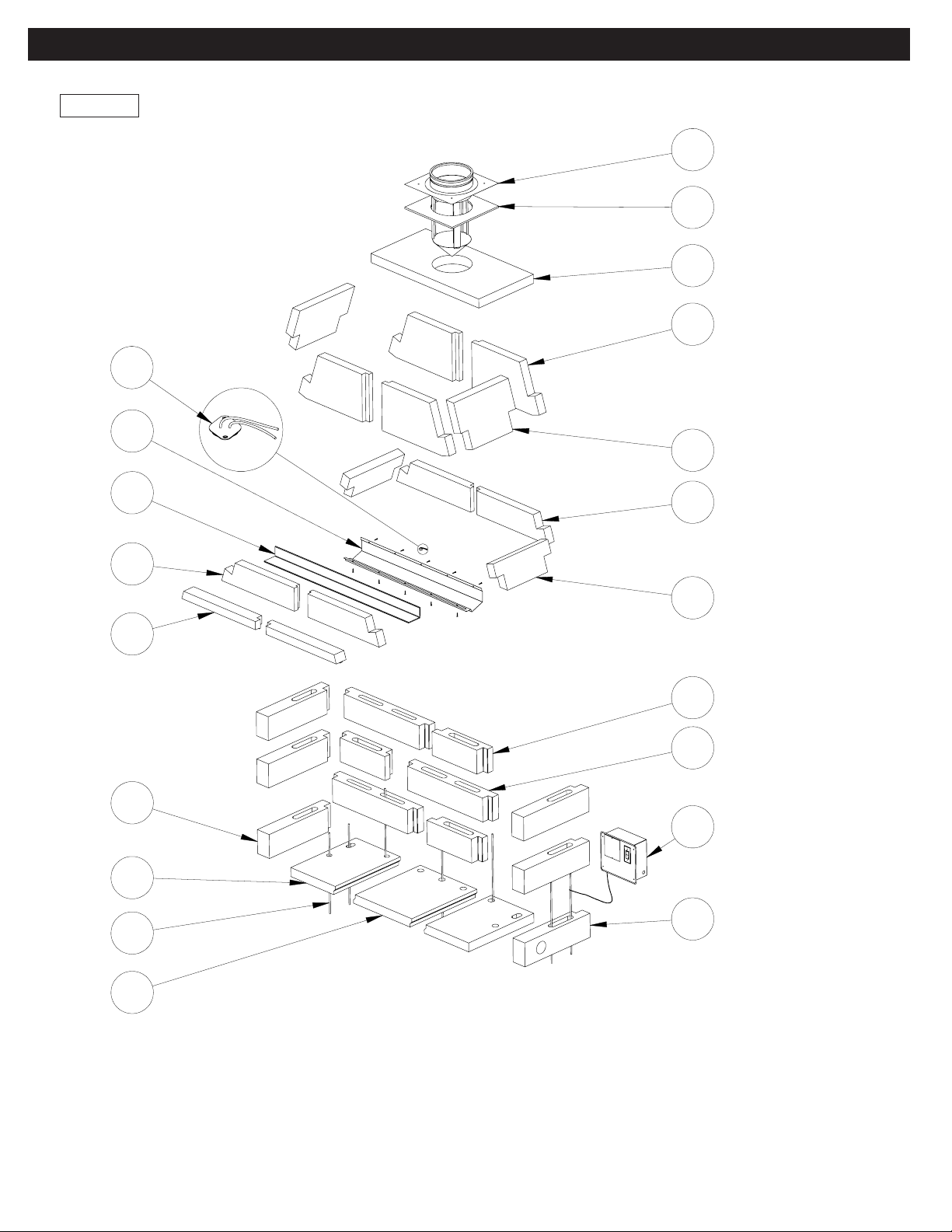
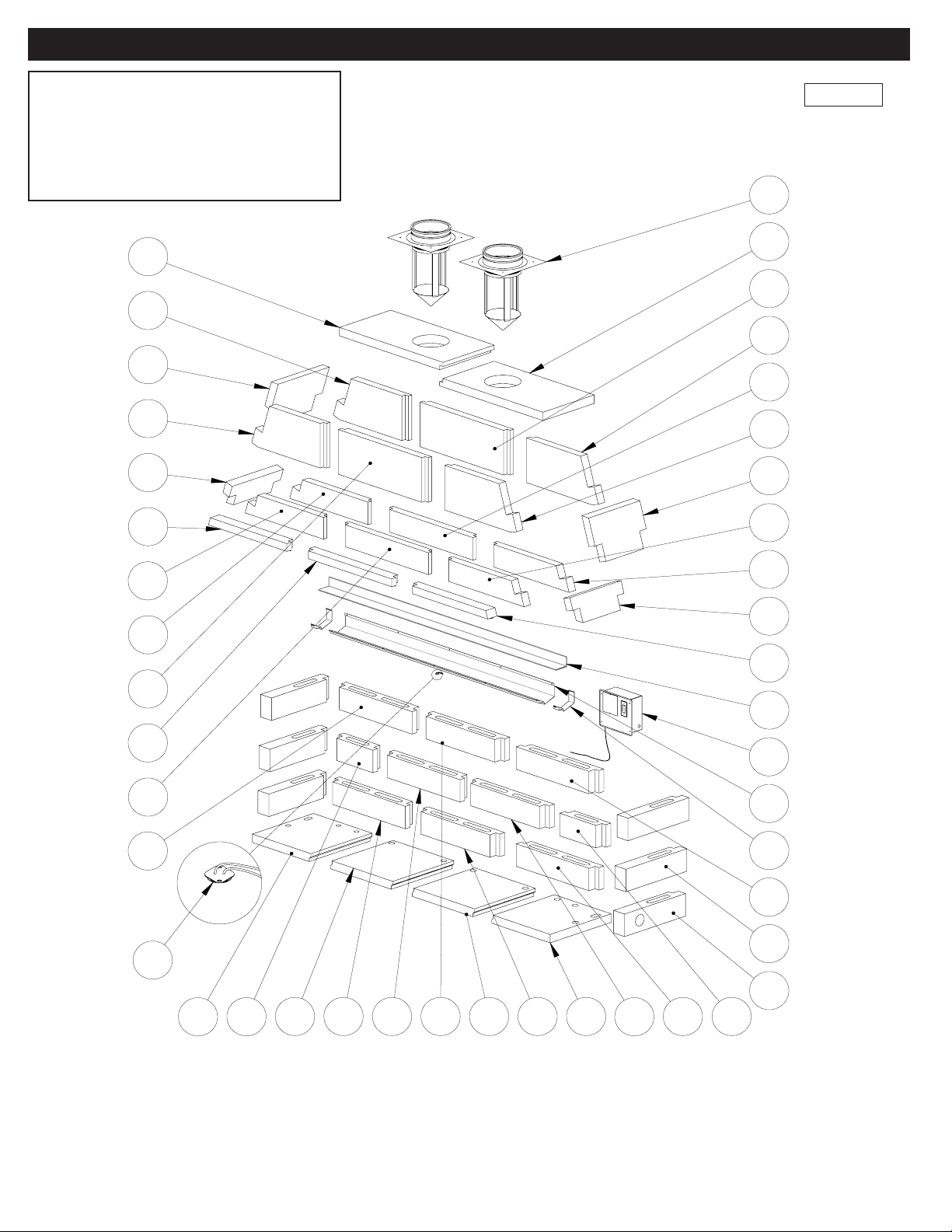
You will nd that the Mason-Lite B-vented Gas Appliance is
designed to be completely assembled on-site, consisting of
interlocking precast parts. The parts of the appliance are made
of Mason-Lite’s incredibly strong blend of specialty cement and
a light weight aggregate.
IMPORTANT! When applying mortar, it is imperative that the
concrete blocks be maintained moist (not soaking) so they don’t
absorb the water out of the mortar and cause adhesion to fail.
Frequently run a damp sponge to the parts before mortar is
applied!
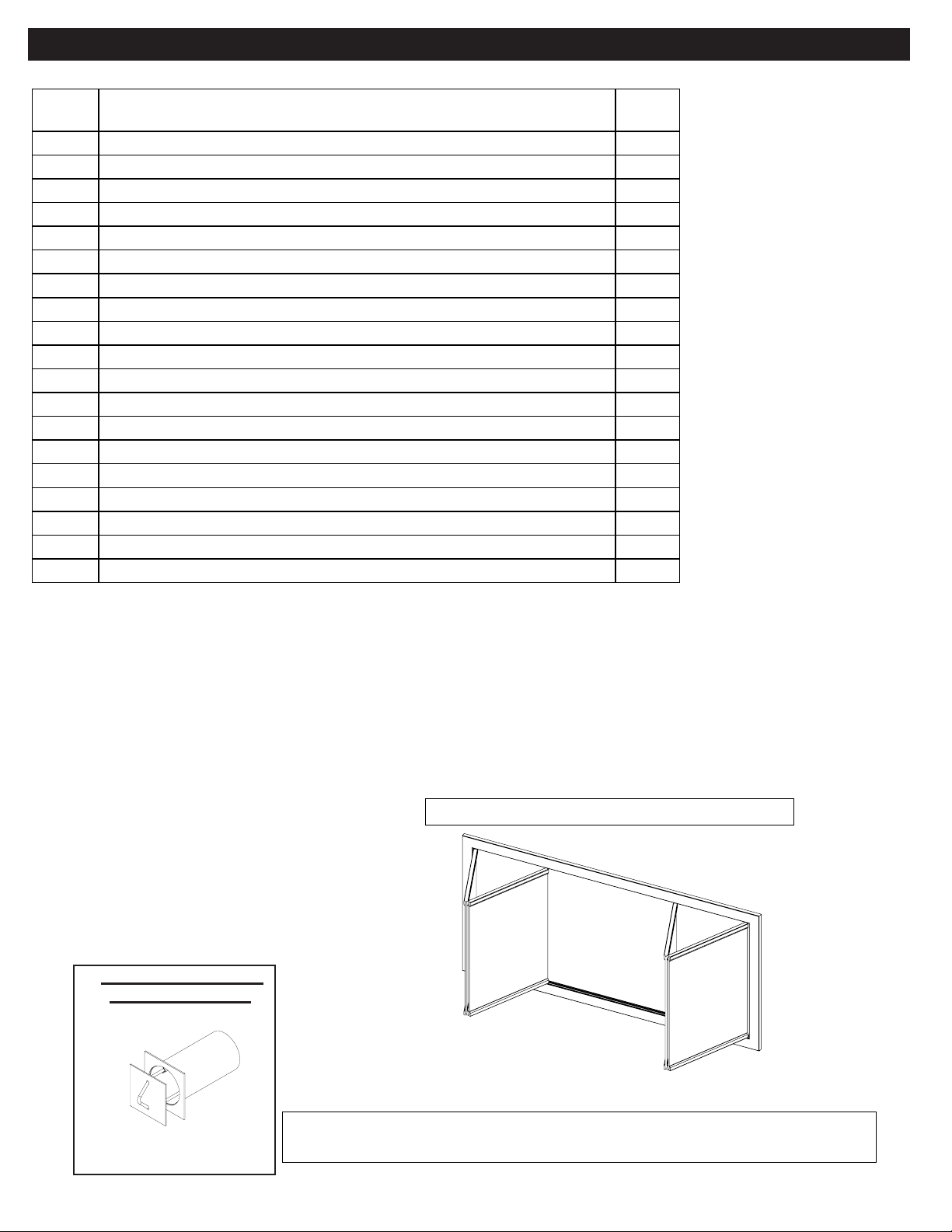
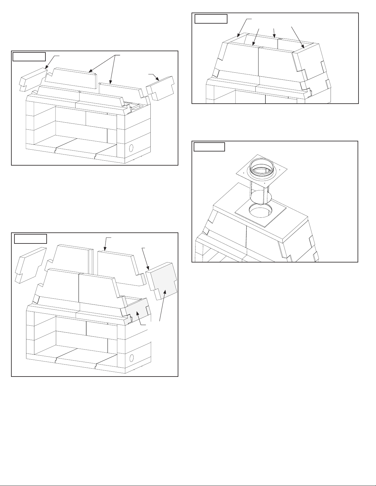
The installation of an anchor plate/damper is required but not
supplied. You may purchase it from any chimney manufacturer
or Masonry Fireplace Industries. Also, an optional combustion
air inlet MFPST-4AK can be obtained from Masonry Fireplace
Industries.
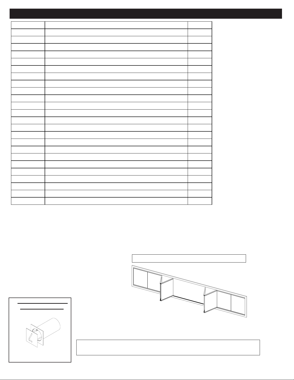
Refractory Firebrick Lining is required. Side and rear wall
rebrick should be a minimum of 1-1/2” thick. Hearth lining
should be a minimum of 2” thick. For more information see
page 21.
Tools needed for installations:
●One 4’ level
●Roto-hammer with ½” drill bit (needed for concrete slab
install only)
●Drill motor with mixer blade (to mix Mason-Lite Mortar)
●Two empty 5 gallon buckets (to mix Mason-Lite Mortar)
●One wheelbarrow and shovel to mix concrete.
●Grout bag
●Triangular masonry trowel
●Rubber hammer
●Sponge and water bucket to wipe down and moisten parts
prior to applying mortar.
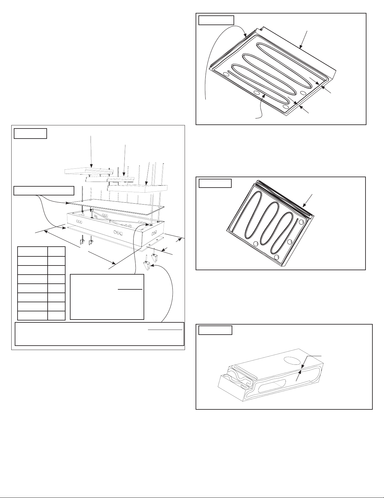
Materials needed for concrete slab installations
LMFP48/60/72:
Six (6) pieces 3/8” rebar x 36” long (included with unit)
Six (6) pieces of rebar x 12” long (included with unit)
LMFP84/96/108/120:
Eight (8) pieces 3/8” rebar x 36” long (included with unit)
Eight (8) pieces of rebar x 12” long (included with unit)
ALL UNITS:
●Epoxy for securing rebar in footing / foundation.
●Three (3) - 90 lb. bags of Ready-Mix Concrete with 1/4” or
smaller aggregate.
Materials needed for wood floor installations
LMFP48/60/72:
Six (6) pieces 3/8” rebar x 36” long (included with unit)
Six (6) ea. All-thread x 12” long (with nuts and washers)
LMFP84/96/108/120:
Eight (8) pieces 3/8” rebar x 36” long (included with unit)
Eight (8) ea. All-thread x 12” long (with nuts and washers)
ALL UNITS:
Three (3) - 90 lb. bags of ready mix concrete with 1/4” or smaller
aggregate.
6” Structural Metal Base to allow 6 inch airspace below the unit
(required for combustible floor systems)
SURFACE CRACKS - The Mason-Lite Appliances are
manufactured using high quality materials. During the
drying process, surface cracking may occur. These small
cracks (under 1/16” will not aect the appliance safety or
performance). During the assembly process, ll surface
cracks with thin-set mortar and brush when drying for a
smooth surface nish.
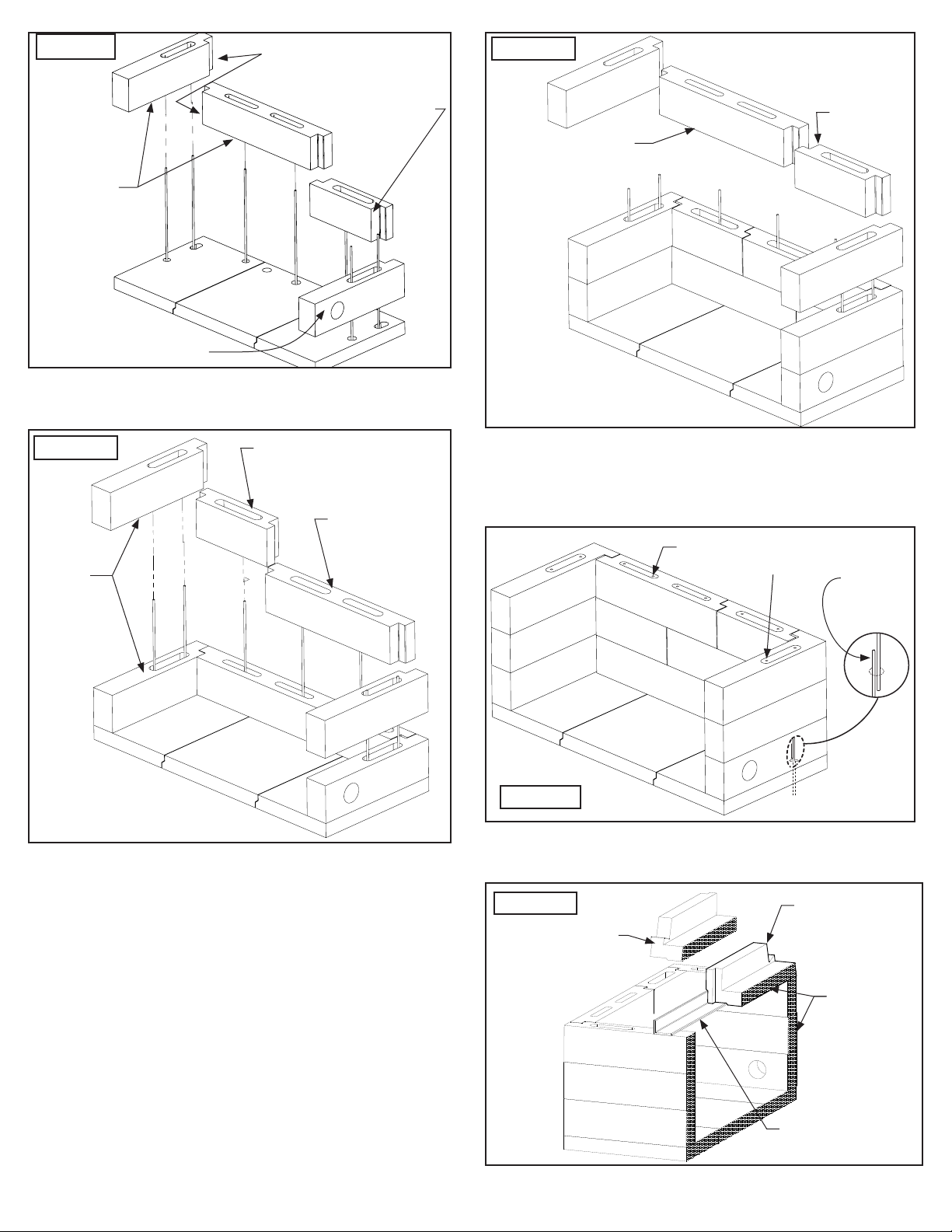
Field Assembly Procedures
a) Mixing the Mason-Lite mortar – The mortar comes premixed
and should be dry. Be sure to use clean water and work it
up into a mixture that is pasty but not lumpy. If it’s too thin
and the surfaces don’t stay moist, the components will not
adhere. Load the mixture into a standard grout bag.
b) Apply about ½” (one-half inch) thread of mortar. The mortar
bead should be approximately ½” (one-half inch) away from
all edges. The mortar has a considerable amount of holding
power so do not overload the components with too much
mortar. Keep the components moist at all times!
c) Some mortar will “ooze out” when placing components
together, this is normal. Wipe excess away with a trowel. Do
not cover component surfaces completely with mortar. Do
not apply the mortar in thick bands even if the component
you are working with is larger than the rest. You will want to
apply “stripes” of mortar in these situations.
d) Make sure components are level. It’s extremely important
that you pay careful attention to how you are assembling
the Mason-Lite Appliance since every component builds on
the next. If you have to make any kind of an adjustment, do
not try to do it “by loading an opening” with mortar, this will
only result in an appliance that will not be plumb or level.
Use wood shims instead. You will nd these small wood
shims supplied with the Mason-Lite Appliance and
you can nudge them in between openings to achieve the
precision you need in making component adjustments.
Once you have removed any shims, you will want to cover
any gaps that may have resulted with the mortar.

18
Assembly Instructions
1. Place the Mason-Lite appliance hearth base parts on top of
your non-combustible oor, metal base or CMU blocks. For
concrete slabs, supporting oor must be ASTM 90 rated.
2. a) Combustible Floor Installations: Position hearth
slabs on top of 6” CMU blocks or Metal Base (Figure 15).
All-thread rods should stick up through the holes on the
hearth slabs when installing metal base.
b) Non-combustible Floor Installations: Position Hearth
Slabs in desired location, check that overall width
measures according to table in Figure 15. Draw an outline
and mark rebar center locations. Remove slabs and drill
holes at rebar centers 4” deep into concrete slab. Secure
rebar with epoxy.
Figure 15
Anchor Bracket All-Thread Rods are secured to the bottom ange
of the Metal Base with eight (8) at washers (2”OD x 9/16”ID x
0.10”) and eight (8) 1/2-13 UNC Nuts.
28”
Center Hearth (2nd)
Left Side Hearth (3rd)
Right Side
Hearth (1st)
W
Model W
LMFP48 62”
LMFP60 74”
LMFP72 86”
LMFP84 98”
LMFP96 110”
LMFP108 122”
LMFP120 134”
Four (4) All-Thread Rods
are secured to the top ange
of the Metal Base with eight
(8) at washers (2”OD x
9/16”ID x 0.10”) and eight
(8) 1/2-13 UNC Nuts.
3. Mix a batch of mortar and prepare bottom surface of Right
Side Hearth to be bonded (Figure 16), then lower the piece
into place on the outline created before. Align lower Right
Side Hearth on the outline created. The width dimension
allows for an approximate gap of 1/8” between slabs for the
additional mortar to unite the remaining slabs. Continue
process for remaining hearth sections while moistening and
adding mortar between joints at slab ends.
Figure 16
1/2” AWAY
FROM EDGES
1/2” MORTAR
BEAD TYPICAL
Hearth section shown prepared
for Right Side position
APPLY MORTAR
BEAD TO ALL
MATING SURFACES
4. Apply mortar in like manner to the Center Hearth and place
next to the Right Side Hearth. Check that surface is LEVEL
and use shims if necessary.
5. Apply mortar to the remaining Hearth except this time apply
beading on surface to be facing oor as shown in Fig. 17.
Figure 17 Hearth shown prepared
for Left Side position
6. Before installing side walls, conrm placement of outside
combustion air access (if required), this can be installed
either side depending on which side is accessible to
outside combustion air (all diagrams in this manual show
the combustion air inlet hole on the right side). Prepare side
wall mating surfaces with the prepared mortar as shown in
Figure 18.
Figure 18 Side Wall shown prepared for Right
Side Air Access.
For Left Side, bead opposite side.
1/2” AWAY
FROM EDGES
7. Keep the assembly of the next sections of the rebox side
walls moving up, keeping components moist, mixing mortar
as you need it and threading the mortar appropriately as you
stack each section, one onto the next. Constantly check for
squareness and levelness while building each course of
block. As you complete each section, make certain that you
adhere the mortar at each and every joint.
1/2” CEMENT BOARD

19
Figure 19
Combustion Air Access
Right or Left (Right shown).
Apply
mortar
Apply mortar
Begin with the smallest
rear wall to the right
side as shown below.
8. Rear walls are staggered on every row as shown in Figures
19 thru 21.
Figure 20
Rear Wall (long)
Rear Wall
(short)
Apply
mortar
Figure 21
Rear Wall (long)
Rear Wall
(short)
Stagger positions of rear wall
9. After the last tier of side walls are installed, place #3 rebar
(3 ft. long pieces) vertically through the cells, into the holes
in the hearth, adjacent to the rebar and/or all-thread
sticking up from the hearth and ll all cells with Ready-Mix
concrete mix (Figure 22).
Figure 22
Add rebar to cells
and ll with mortar. 12 inch
rebar or
all-thread
Set the Angle Iron then the Right and Left Lintel as shown
in Figure 23. Front face of lintel needs to be ush to the
front face of the side walls.
Figure 23
Left Side Lintel
Front faces to
be ush
Right Side
Lintel
Angle Iron

20
Important: Adjustments can only be made while the mortar
is still wet when correcting for squareness and leveling.
10. Assemble Dome Sides and Lower Rear Domes as shown
in Figure 24. The beveled face lines up with the inward
angles of the lintel sides.
Figure 24 Dome Side
Dome Side
Mid Lower
Dome Rear
If you need to make adjustments, use shims between the
lowest wall component and the top surface of the base plate.
Once leveled, ll any resulting gaps with mortar.
11. Assemble Upper Domes and Dome Sides as shown in
Figure 25. Check your assembly here. If things are
proceeding as they should be, the nished top surface
should be at and level (Figure 26).
Figure 25 Upper Dome
Upper Side
Dome
Dome side
faces to be
ush
As you are connecting each Mason-Lite component, be certain
you are following the instructions given previously for using
Mason-Lite mortar. Stop to look at the smoke dome side, front
and rear walls to see that they are aligning correctly and that
the surfaces are smooth and uniform. Make sure connections
are covered with an adequate amount of mortar. Remember
that you have the option of using shims but they must be
removed and any holes lled. Make any adjustments to the
appliance alignment before continuing to the next step.
Figure 26 Top surfaces to be
ush and level
12. Finally, set the Dome Top into position. Be sure that it is
ush in every direction as you place it on the crest of the
smoke dome wall assembly (see Figure 27).
Figure 27 Make sure center of
Ø12” B-Vent hole is
centered.
Installing Draft Hood and Chimney System
Before installing your B-vent to the Mason-Lite Firebox you
must install the draft hood (not supplied). The draft hood is
pre-drilled with holes for four (4) cement Tapcon screws (not
supplied).
1. Place insulation blanket as shown in Figure 27.
2. Place the draft hood on top of the appliance directly over
the hole in top of the appliance and drill pilot holes for the
Tapcon screws.
3. Apply hi-temp silicone around the base of the draft hood
and top of the appliance to create a good seal.
4. Install the draft hood pressing draft hood into the silicone.
Screw in the 4 Tapcon screws to hold draft hood in place.
This manual suits for next models
6
Table of contents