MFJ Enterprises MFJ-1272B User manual

MFJ-1272B TNC/Microphone Switch
Introduction
Thank you for purchasing the MFJ-1272B TNC/MIC Switch.
This switch is designed to allow simultaneous
connection of both your microphone and your TNC to the
radio.
The MFJ-1272B microphone switches were designed to be
used with any radio that has a standard, round, 8-pin
microphone connector. Because many TNCs have different
connectors, MFJ offers 5 models:
MFJ Model Number TNC and Multimodes
MFJ-1272B All MFJ TNCs, TAPR TNC II clones, and PK-
12/96/900
MFJ-1272BX PK-232
MFJ-1272BYV KAM® VHF port, KPC-2, KPC-3
MFJ-1272BYH KAM HF port
MFJ-1272BZ PK-88
For circuit board revisions, refer to page 11.
CAUTION
Always check your radio's owner's manual to see if
there is a voltage on one of the pins of the microphone
before hooking up the microphone switch. You could
damage your radio by connecting the PTT line to a
voltage source. Do not connect any pin labeled as a
voltage source to PTT !
WARNING:MFJ Enterprises, Inc. is not responsible for
damaged radios or associated equipment. It is
your responsibility to make sure your
connections will not damage the radio.

MFJ-1272B Instruction Manual
2
KAM is a registered trademark of Kantronics Company, Inc.

MFJ-1272B Instruction Manual
3
Installation
Before you install the MFJ-1272B TNC/MIC switch, you
must set it up for your particular radio. The MFJ-
1272B comes pre-wired from the factory for Kenwood and
Alinco radios without RECEIVE AUDIO on the microphone
jack. If you have one of these radios, the TNC/MIC
switch is ready to use. If you have a Kenwood or
Alinco radio with RECEIVE AUDIO on the microphone jack,
or if your radio is not a Kenwood or Alinco refer to
the configuration section. We have given a few
diagrams for placing the internal jumpers for a few
popular radios on Page 6.
Configuration
If you must configure the TNC/MIC switch for your
radio, please follow this procedure.
1. Remove the two screws and top cover of the MFJ-
1272B.
2. Look at the writing on the unit's pc board. Please
refer to Tables 1 thru 6 as to where to place the
jumpers in relation to the pinouts on your radio.
Consult your radio's manual and the definitions
below to match signals.
Audio Out:
Audio to the from either the TNC or radio
MICROPHONE.
PTT:
This is the Push to talk signal from either the TNC
or radio microphone.
Receive:
Audio from the radio to the TNC. Please refer to
the External Audio section on the following page, if
you use external audio make no connection here.
Audio In:
Audio from mic (same # as Audio Out)

MFJ-1272B Instruction Manual
4
Ground:
This is the system ground on radio's mic connector.
Some radios have two ground pins, MICROPHONE GROUND
and GROUND. The microphone ground should not be
used, due to the possibility of introducing "hum"
into the system.Always use the pin labeled ground.
Throughs:
Connect all pins here except MICROPHONE AUDIO.

MFJ-1272B Instruction Manual
5
(unlabled)
if you use external audio do not connect the radio
pins for Receive
3. Header HD3 controls the RECEIVE AUDIO to the
EXTERNAL SPEAKER. Place a push-on jumper on pins 2
and 3 if you want the external speaker "on" all of
the time. Place the jumper on pins 1 and 2 if you
want the external speaker "off" when using the TNC.
Most people prefer not to hear audio during packet.
4. Replace the top and screws.
External Audio
If your radio does not have RECEIVE AUDIO on the
microphone, then we suggest the use of an inter-
connecting to supply RECEIVE AUDIO to the TNC/MIC
switch. You would connect a cable from an external
speaker or headphones jack on your radio to the AUDIO
IN jack of the TNC/MIC switch. Therefore, no jumper
connection should be made for Receive on the pc board.
Using the method above for connecting RECEIVE AUDIO to
the TNC/MIC switch, will cut off the internal speaker
inside the radio. In this case, you must connect an
external speaker to the EXT. SPEAKER jack on the
TNC/MIC switch. Otherwise, you will not be able to
hear any signals at all from your radio.
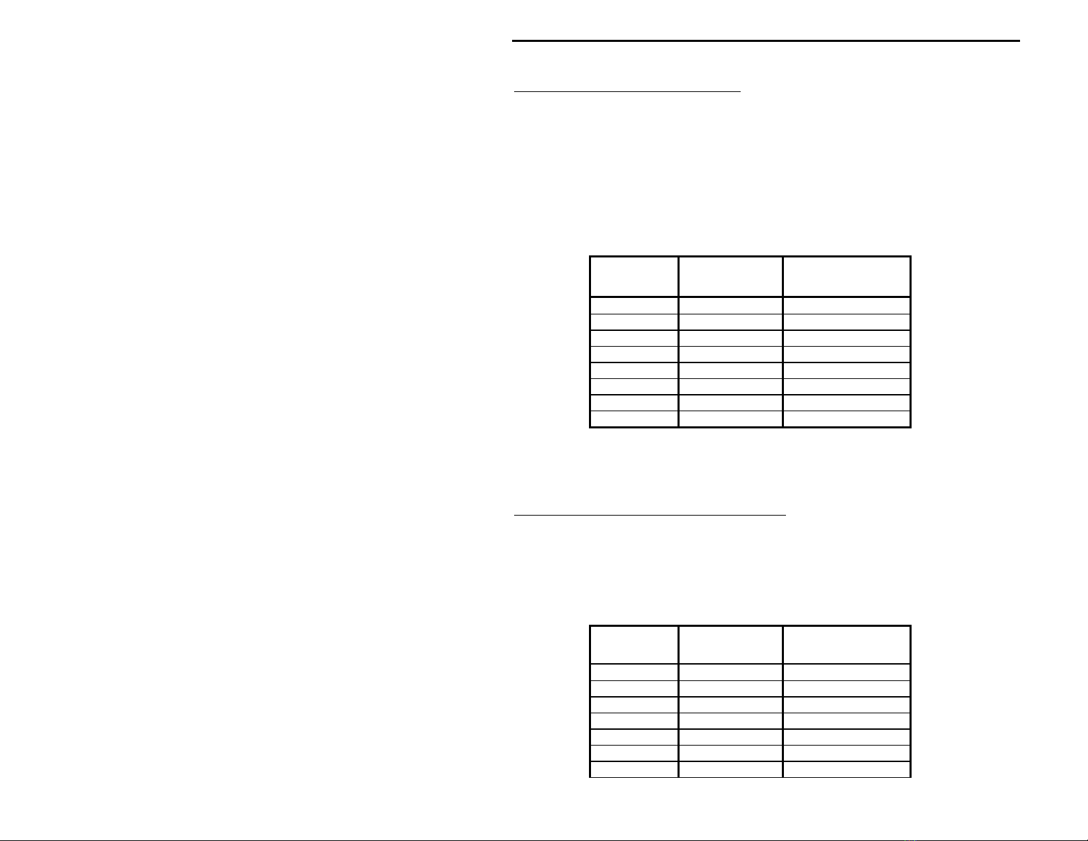
Jumper Configuration
Because there are so many different radio
configurations, we have tried to make the MFJ-1272B as
versatile as possible. With the MFJ-1272B you can
virtually connect any radio pin to just about any TNC
pin, just by configuring the jumpers properly. The
following tables will show how to set the jumpers,
depending on the TNC functions versus the MIC pins of a
particular radio. Be sure to follow the tables closely
with your radio manual, to verify that you are not

MFJ-1272B Instruction Manual
6
shorting any microphone voltages or any other
microphone signals to GROUND !

MFJ-1272B Instruction Manual
7
Receive Audio Connections
Table 1 below shows where you would place a jumper if
your radio had RECEIVE AUDIO on one of the microphone
pins. For example, if your radio had RECEIVE AUDIO on
pin 3 on a Kenwood microphone, you would place a jumper
on position, R3A in the RECEIVE section of header HD1.
If your radio does not have RECEIVE AUDIO on one of the
microphone pins, then do not place a jumper in the
RECEIVE section of header HD1.
Radio MIC
Pin
MFJ-1272B
Header Place a jumper
on:
1 HD1 RECEIVE--R1A
2 HD1 RECEIVE--R2A
3 HD1 RECIEVE--R3A
4 HD1 RECEIVE--R4A
5 HD1 RECEIVE--R5A
6 HD1 RECEIVE--R6A
7 HD1 RECEIVE--R7A
8 HD1 RECEIVE--R8A
Table 1
*Refer to External Audio, page 3
PTT (Push-to-Talk) Connections
Table 2 below shows where you would place a jumper,
depending on what microphone pin is designated PTT.
For example, if PTT is designated as being pin 4 on a
Kenwood microphone, then you would place a jumper on
position R4B in the PTT section of header HD1.
Radio MIC
Pin
MFJ-1272B
Header Place a jumper
on:
1 HD1 PTT--R1B
2 HD1 PTT--R2B
3 HD1 PTT--R3B
4 HD1 PTT--R4B
5 HD1 PTT--R5B
6 HD1 PTT--R6B
7 HD1 PTT--R7B

MFJ-1272B Instruction Manual
8
8 HD1 PTT--R8B
Table 2

MFJ-1272B Instruction Manual
9
Audio Out Connection
Table 3 below shows where you would place a jumper,
depending on what microphone pin is designated
MICROPHONE AUDIO. The microphone pin, designated
MICROPHONE AUDIO, is the where the transmit audio from
the TNC comes into the radio. For example, if
MICROPHONE AUDIO is designated pin 1 on a Kenwood
microphone, then you would place a jumper on position
R1C in the AUDIO OUT section of header HD1.
Radio MIC
Pin
MFJ-1272B
Header Place a jumper
on:
1 HD1 AUDIO OUT--R1C
2 HD1 AUDIO OUT--R2C
3 HD1 AUDIO OUT--R3C
4 HD1 AUDIO OUT--R4C
5 HD1 AUDIO OUT--R5C
6 HD1 AUDIO OUT--R6C
7 HD1 AUDIO OUT--R7C
8 HD1 AUDIO OUT--R8C
Table 3
Ground Connections
Table 4 below shows where you place a jumper, depending
on what microphone pin is designated GROUND. For
example, if GROUND is designated as being pin 7 on a
Kenwood microphone, then you would place a jumper on
position R7D in the GROUND section of header HD2.
Radio MIC
Pin
MFJ-1272B
Header Place a jumper
on:
1 HD2 GROUND--R1D
2 HD2 GROUND--R2D
3 HD2 GROUND--R3D
4 HD2 GROUND--R4D
5 HD2 GROUND--R5D
6 HD2 GROUND--R6D
7 HD2 GROUND--R7D
8 HD2 GROUND--R8D

MFJ-1272B Instruction Manual
10
Table 4
Most radios have two ground pins on the microphone,
GROUND and MICROPHONE GROUND. Be sure to use the pin
designated as ground, not microphone ground, when
making your jumper connections. The use of the
microphone ground could introduce audio hum in the
system.

MFJ-1272B Instruction Manual
11
Through Connections
Table 5 below shows where you would place a jumper,
depending on the microphone pin functions that are not
to be switched by the MFJ-1272B. Microphone pins
designated, +V, UP and DOWN, are radio functions that
are not needed by the TNC, but are needed for normal
microphone operations. For example, if on a Kenwood
microphone pin 3 is designated as being UP, which would
be for increasing your frequency readout on the radio,
then you would place a jumper on position, R3E-M3A on
header HD2.
Radio MIC
Pin
MFJ-1272B
Header Place a jumper
on:
1 HD2 R1E--M1A
2 HD2 R2E--M2A
3 HD2 R3E--M3A
4 HD2 R4E--M4A
5 HD2 R5E--M5A
6 HD2 R6E--M6A
7 HD2 R7E--M7A
8 HD2 R8E--M8A
Table 5
Mic Audio Connections
Table 6 below shows where you place a jumper, depending
on what microphone pin is designated MICROPHONE AUDIO.
For example, if MICROPHONE AUDIO is designated as being
pin 5 on a Kenwood microphone, then you would place a
jumper on position, M5B in the AUDIO IN section of
header HD2.
Radio MIC
Pin
MFJ-1272B
Header Place a jumper
on:
1 HD2 AUDIO IN--M1B
2 HD2 AUDIO IN--M2B
3 HD2 AUDIO IN--M3B
4 HD2 AUDIO IN--M4B
5 HD2 AUDIO IN--M5B

MFJ-1272B Instruction Manual
12
6 HD2 AUDIO IN--M6B
7 HD2 AUDIO IN--M7B
8 HD2 AUDIO IN--M8B
Table 6

MFJ-1272B Instruction Manual
13
Jumper positions for specific radios:

MFJ-1272B Instruction Manual
14
Jumper positions for specific radios:

MFJ-1272B Instruction Manual
15
Connections
Connection of the MFJ-1272B is very simple.
1. Connect your radio's microphone to the microphone
connector on the front panel of the MFJ-1272B. Be
careful not to bend any of the microphone connector
pins. If the microphone plug does not insert
easily, then do not force it. Find out what the
problem is. Tighten the threaded portion of the
microphone securely.
2. Connect the 8-pin MIC plug which exits the rear of
the MFJ-1272B, to the microphone connector on the
radio. Be careful not to bend any of the microphone
connector pins. If the microphone plug does not
insert easily, then do not force it. Find out what
the problem is. Tighten the threaded portion of the
microphone securely.
3. Connect the TNC cable which exits the rear of the
MFJ-1272B, to the TNC.
External Receive Audio Connection
If you have a radio without RECEIVE AUDIO on the
microphone connector, you will need to perform steps 4
and 5.
4. Connect a cable from the headphones or speaker out
jack of the radio to the AUDIO IN jack of the MFJ-
1272B. The AUDIO IN jack on the TNC/MIC switch
requires an RCA male phono plug.
5. Connect a speaker to the EXT. SPKR. jack on the back
of the MFJ-1272B. The EXT. SPKR. jack requires a
3.5mm mono plug, with the tip being positive and the
sleeve being ground.

MFJ-1272B Instruction Manual
16
Technical Assistance
If you have any problem with this unit first check the
appropriate section of this manual. If the manual does
not reference your problem or your problem is not solved
by reading the manual you may call MFJ Technical Service
at 601-323-0549 or the MFJ Factory at 601-323-5869. You
will be best helped if you have your unit, manual and all
information on your station handy so you can answer any
questions the technicians may ask.
You can also send questions by mail to MFJ Enterprises,
INC., 300 Industrial Park Road, Starkville, MS 39759; by
FAX to 601-323-6551; through Compuserve at 76206,1763; or
description of your problem, an explanation of exactly
how you are using your unit, and a complete description
of your station.
Our goal is to provide you, the customer, with the best
technical assistance we can, and to see that it is as
accurate as possible.

MFJ-1272B Instruction Manual
17
Circuit Board Revisions
Note: This manual is written for the Revision 9
circuit board, pictured on the
right. The only difference between revisions 8
and 9 is the pin labeling
of the connectors HD1 and HD2. If your board is
revision 8, please
refer to the labeling of the revision 9 board.

MFJ-1272B Instruction Manual
18
Schematic

MFJ-1272B Instruction Manual
19
Table of contents
Other MFJ Enterprises Switch manuals
Popular Switch manuals by other brands

Kramer
Kramer VP-734 quick start guide

Allen-Bradley
Allen-Bradley 440G-TZS21UPRH installation instructions

Perle
Perle IDS-1 HP Series installation guide

FlyThisSim
FlyThisSim TouchTrainer Setup guide

Allied Telesis
Allied Telesis AT-8324SX Quick install guide

Johnson Controls
Johnson Controls FS80-C installation instructions

Ruijie
Ruijie RG-PF2920 Series Hardware installation and reference guide

THOMSON
THOMSON TS 880 Service manual

Dell
Dell Networking C9010 Getting started guide

Cabletron Systems
Cabletron Systems Cabletron CyberSWITCH CSX5500 quick start

HP
HP FlexFabric 5700 series Configuration guide

Bones
Bones TWIN-CITY AB/Y owner's manual